


Overview
Source: Laboratory of Dr. Yuriy Román — Massachusetts Institute of Technology
A potentiostat/galvanostat (often referred to as simply a potentiostat) is an instrument that measures current at an applied potential (potentiostatic operation) or measures potential at an applied current (galvanostatic operation) (Figure 1). It is the most commonly used instrument in the electrochemical characterization of anode and cathode materials for fuel cells, electrolyzers, batteries, and supercapacitors.
Conventionally, these anode and cathode materials are interfaced with a potentiostat via a three-electrode electrochemical cell. The electrode leads from the potentiostat are connected to the reference electrode, the counter electrode (often called the auxiliary electrode), and the working electrode (which contains the test material of interest). The electrochemical cell is then filled with a high ionic strength electrolyte solution, such as an acidic, alkaline, or salt solution. The media for this high ionic strength solution is typically aqueous; however, for applications necessitating higher operating cell potential windows, such as batteries and supercapacitors, non-aqueous media is often used. The cell media is degassed with an inert gas (to prevent unwanted side reactions) or with a test gas (if the test reaction involves a gas at one of the electrodes).
Alternatively, a salt bridge or membrane is employed to maintain ionic contact if the two half cells are to be measured in different electrolytes. In heterogeneous electrocatalysis, this type of "two compartment" cell is often used if the test molecule at the working electrode is also reactive at the counterelectrode. This happens frequently as the counterelectrode typically employed is platinum, which is a highly active catalyst for many reactions. Here, single compartment cells will be used, where all three electrodes are in the same media.
This video will explain the process of polishing a working electrode, preparing a catalyst ink, mounting the catalyst ink onto the working electrode, preparing the electrochemical cell, and then performing electrochemical measurements. The measurements that are performed include: cyclic voltammetry (CV), linear sweep voltammetry (LSV), chronopotentiometry (CP), and chronoamperometry (CA).
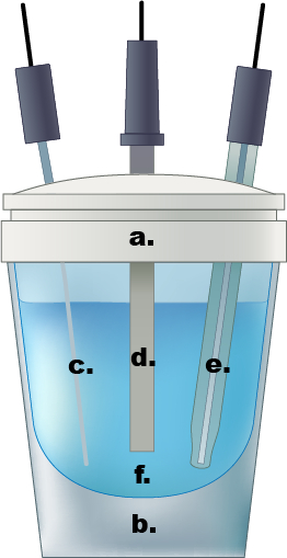
Figure 1. An example of a single compartment electrochemical cell. a.) Teflon cap, b.) glass cell, c.) Pt wire counter electrode, d.) working electrode, e.) Ag/AgCl reference electrode, f.) 0.5 M aqueous sulfuric acid electrolyte solution.
Principles
The potentiostat can be used to apply a constant anodic or cathode potential to the working electrode and measure the resulting anodic or cathodic current (chronoamperometry) or the potentiostat can be operated galvanostatically via a feedback control loop and apply a constant anodic or cathodic current with the measured potential varying with time to maintain this applied current (chronopotentiometry). Alternatively, potential space may be explored with time using cyclic voltammetry or linear sweep voltammetry to measure anodic and cathodic potentials versus an applied potential scan rate (the derivative of potential with respect to time).
In all of these techniques, even during galvanostatic operation, the potentiostat controls the applied potential and measures the flow of electrons from (to) the working electrode to (from) the counter electrode when the working electrode is acting as the anode (cathode). The applied potential is referenced against the reference electrode, which contains a redox system (such as a silver chloride electrode or saturated calomel electrode) with a known and stable potential that is interfaced with the electrolyte solution via a porous frit. During normal operation, the potentiostat draws a negligible but nonzero current through the reference electrode so that an accurate potential can be applied to the working electrode. While the potentiostat measures the flow of electrons to or from one half reaction to the next, the electrolyte solution completes the circuit by preventing charge buildup at either the anode or the cathode.
Subscription Required. Please recommend JoVE to your librarian.
Procedure
1. Catalyst Ink and Working Electrode Preparation
Safety Precautions: Metals supported on carbon black must be handled in a fume hood or balance enclosure until it is in suspension form as these powders are inhalation hazards.
- Using an enclosed balance, weigh out 5–10 mg of metal/carbon black catalyst and add to a glass vial with a cap.
- Using a micropipette, dilute the catalyst with water such that the final concentration is 7.5 mg of catalyst per mL of water.
- While sonicating, 100 µL of Nafion 117 solution per mL of water is added to the suspension.
- The ink should be sonicated for at least 10 min to ensure uniform dispersion and complete mixing of the carbon black support with the binding agent.
- While the ink is sonicating, a 3 mm glassy carbon disk electrode should be cleaned and polished by rubbing it in a swirling circular motion on a soft alumina pad covered with 0.05 µm alumina solution. It should then be rinsed copiously with water to remove the alumina.
- Next, 7 µL of ink is dripped onto a polished, vertically-oriented 3 mm glassy carbon disk electrode. The working electrode is then dried at 80 ˚C for 1 h if the catalyst is air-stable or evaporated under a weak vacuum for 30 min if the catalyst is air-sensitive.
2. Electrochemical Cell Preparation
Safety Precautions: Gloves, labcoat, and safety glasses must always be worn but is especially paramount for working with the sulfuric acid solution. Should any drops of solution spill onto the wrists, it must be washed with soap and water for 15 min. For major spills, removal of contaminated garments and use of the eyewash or showers should be used for 15 min followed by a medical consultation. The electrical leads should not be touched once placed onto the electrochemical cell.
- A glass cell is filled with 10 mL of 0.5 M H2SO4 and degassed for at least 30 min with an ultra high purity nitrogen stream
- The Teflon caps of the electrochemical cells have 3 ports for the working electrode, counter electrode, and the reference electrode
- The Ag/AgCl reference electrode is removed from its 1 M KCl solution, rinsed thoroughly with DI water, and then placed into the cell.
- The platinized platinum wire counter electrode is rinsed thoroughly with DI water and then placed into the cell.
- The dried working electrode is rinsed with DI water and then placed into the cell.
- The potentiostat is turned on.
- The white electrode lead is connected first and connected to the reference electrode.
- The red electrode lead is then connected to the Pt wire counter electrode.
- The green electrode lead is then connected to the metal/carbon black working electrode.
- A small N2 purge stream is left continuously bubbling in the electrolyte.
- Ensure no leads are touching and that there is no direct electrical contact between the 3 electrodes other than with the 0.5 M H2SO4 electrolyte.
3. Electrochemical Analysis
- After turning on the potentiostat, perform at least 20 conditioning cycles between 0 and 0.4 V vs. RHE at 50 mV/s using CV. This is performed by choosing CV as a technique and entering the upper and lower potential limits as well as the scan rate.
- Linear Sweep Voltammetry (LSV) can then be performed by choosing LSV as a technique and specifying a starting potential, a final potential, and a scan rate. The scan rate for LSV is typically much less than CV, usually 1 – 2 mV/s so that capacitive currents become much lower than currents arising from faradaic surface reactions
- Chronoamperometry (CA) is performed by choosing CA or "Amperometric i-t curve" as a technique and specifying the fixed potential as well as the length of time the instrument should hold the working electrode as this fixed potential.
- Chronopotentiometry (CP) is performed by choosing CP as a technique. CP can be performed in a series of current steps where one current is specified for a certain length of time followed by a new current for a specified length of time. These applied currents can span both anodic and cathodic currents within the same CP measurement.
- When the electrochemical analysis is finished, turn off the potentiostat.
- Disconnect the electrode leads and store them in a dry place away from any liquids to prevent corrosion.
- Remove the reference electrode and rinse with copious amounts of DI water. Then return the reference electrode directly to its 1 M KCl storage solution. The tip of this electrode should never be allowed to become dry.
- Remove the Pt wire counter electrode and rinse thoroughly with DI water
- Remove the working electrode and rinse thoroughly with DI water and then use a Kimwipe with acetone to easily remove the dried catalyst ink from the working electrode surface. It is recommended to polish electrodes immediately after use.
- Turn off the N2 purge.
- Empty the used electrolyte into an acidic waste container. Rinse the glass cell and Teflon cap with copious amounts of DI water.
A potentiostat-galvanostat is the most commonly used instrument in electrochemical characterization, and is used to understand the effect of electrical changes on a chemical reaction.
A potentiostat-galvanostat is an instrument used in electrochemical systems. It measures current at an applied potential in potentiostat mode, or vice versa in galvanostat mode. For simplicity, the instrument is commonly called a potentiostat.
Oxidation-reduction, or redox, reactions occur at an electrode surface and involve the transfer of electrons. In particular, the loss of electrons in a chemical species is the case of oxidation, or the gain of electrons in the case of reduction. This redox event can be induced by an applied potential, E, also called voltage.
This video will demonstrate the set up and performance of electrochemical tests using a potentiostat.
In most cases, redox events are coupled to a potentiostat via a three-electrode cell. The three-electrode cell consists of a working electrode, counter or auxiliary electrode, and reference electrode. The working electrode is where the reaction of interest occurs, and the counter electrode is used to complete the electrical circuit.
An applied potential is measured against the reference electrode, which contains a redox system with a known, stable electrode potential, E. Common reference electrodes are the saturated calomel electrode, and the reversible hydrogen electrode, which are used for calibration purposes. The Ag/AgCl electrode is commonly used in electrochemical tests, and is interfaced with the electrolyte solution via a porous frit.
The electrochemical cell is filled with a high ionic strength electrolyte solution, such as an acidic, alkaline, or salt solution. The electrolyte solution prevents charge buildup at the electrodes.
In an electrochemical experiment, potential, current, time, and charge can all be manipulated or measured by the potentiostat. When the working electrode is acting as the cathode, electrons flow from the counter electrode to the working electrode. Positively charged ions, or cations, flow to the cathode. The reverse is true when the working electrode is acting as the anode. Negatively charged ions, or anions, flow to the anode.
By selecting the manipulated and measured parameters, a number of measurement techniques are possible. Chronoamperometry is a technique where a potential step is applied to the working electrode, and the resulting current change is measured as a function of time. When a potential step is large enough to cause an electrochemical reaction at the working electrode, the current changes. This technique can be used for many applications, such as the determination of diffusion coefficients in reaction kinetics.
Similarly, chronopotentiometry is a technique where a constant or varied current is applied, and the potential is measured as a function of time. The applied current causes electroactive species to be oxidized or reduced at a certain rate. This technique is used for a range of applications, such as the determination of reaction progress.
Voltammetry measures anodic and cathodic current with respect to an applied potential sweep. This measurement examines the addition or removal of electrons from a chemical species during the increase or decrease of potential at a constant rate. Cyclic voltammetry, or CV, is covered in depth separately in another video in this collection.
Now that the basics of voltammetry have been covered, the preparation of a three-electrode cell and a working electrode with a surface bound catalyst will be demonstrated in the laboratory. In this demonstration, catalyst ink will be prepared and measured, which consists of platinum nanoparticles in a carbon black support, with a Nafion binding agent. This system is representative of current fuel cell and battery research.
To begin, weigh 7.5 mg of metal/carbon black catalyst in a fume hood, and add it to a glass vial. Dilute the catalyst with 1 mL of water and add 100 μL of Nafion 117, then cap the vial.
Sonicate the mixture on ice for at least 10 min to ensure uniform dispersion and complete mixing of the carbon black support with the Nafion. While the ink is sonicating, prepare the working electrode, which is a 3-mm glassy carbon disk.
Clean and polish the electrode by gently rubbing it in a swirling, circular motion on a soft pad covered with 0.05 μm colloidal alumina solution. After polishing, rinse the electrode copiously with deionized water to remove the alumina.
Next, 7 mL of ink is dripped onto the polished, vertically oriented glassy carbon electrode. Dry the working electrode under vacuum at room temperature. Then dry it at 80 °C for one hr if the catalyst nanoparticles are air stable.
First, fill the glass electrochemical cell with 10 mL of the electrolyte. Cap the electrochemical cell with a Teflon cap with openings for the three electrodes. De-gas the electrolyte for at least 30 min with ultra high purity nitrogen gas in order to remove redox-active oxygen. Allow the nitrogen to bubble lightly throughout the experiment.
Remove the Ag/AgCl reference electrode from its 3 M NaCl storage solution. Rinse the electrode thoroughly with deionized water, and place it into the electrochemical cell.
Next, rinse the platinum wire counter electrode and the dried working electrode with deionized water, and insert them into the cell. Ensure that the electrodes do not touch. Turn on the potentiostat, and connect the leads to the reference and counter electrodes.
Perform at least 20 conditioning cycles by running cyclic voltammetry scans between the upper and lower potential limits at 50 mV per second. This step ensures that the electrode surfaces are fully hydrated.
Linear sweep voltammetry, or LSV, can be performed by specifying the initial and final potentials, and the scan rate. The scan rate for LSV is typically less than that for CV. The result is a plot of potential vs. current with oxidation or reduction events visualized as peaks in the scan. In this case, the perchlorate in the electrolyte was reduced on the catalyst surface in the cathodic scan.
To perform chronoamperometry, select it as the technique, then specify the fixed potential as well as the time. The result is a plot of current vs. time. The initial decay is due to capacitive discharging, while the steady state portion is essentially a straight line. Chronoamperometry is potentiostatic and thus after the initial asymptotic decay of the capacitative effects, the current attributed to surface reactions can be isolated.
Finally, chronopotentiometry is performed in a series of current steps, where one current is specified for a certain length of time. Each time the current switches from zero to the working current, there is an initial asymptotic change in potential, followed by a steady state. After each on/off cycle, the stable catalyst material requires the same over-potential to drive the specified current.
Electrochemical measurements with a potentiostat are widely used in analysis and fabrication.
Electrochemistry is used to analyze the binding of probe molecules to electrodes. In this example, electrodes were patterned within microfluidic channels, and functionalized with single stranded DNA. When the DNA was hybridized with the complimentary strand, the redox couple was blocked at the electrode surface.
DNA hybridization was then measured by connecting the electrodes to the potentiostat using three probe electrodes.
Impedance measurements, a measure of the resistance to current flow, showed that increasing complimentary DNA concentration resulted in increased impedance, and therefore increased hybridization.
Next, electrochemical processes were used to monitor and characterize the growth of biofilms on an electrode. For this, a three-electrode cell was assembled, with the electrolyte being the cell broth.
The growth of the biofilm was monitored using chronoamperometry, in order to achieve an exact measurement and reproducible culture conditions.
Electrochemical techniques can also be used in the fabrication of thin films and layers on an electrode surface. Electrical signals trigger localized environments at the electrode surface, which can induce the self-assembly of materials.
In this example, the deposition of biomaterials was performed using electrodeposition. Chitosan, a biopolysaccharide, undergoes a sol-gel transition at the electrode surface, creating a film.
You've just watched JoVE's introduction to potentiometry. You should now understand how to set up a typical three-electrode cell, and perform basic electrochemical tests.
Thanks for watching!
Subscription Required. Please recommend JoVE to your librarian.
Results
This procedure will result in figures containing plots of measured current vs. potential for each of the four techniques. By convention for CV and LSV, the plots will also be outputted as measured current vs. potential despite the reality that these are transient techniques that measure current vs. the time derivative of potential.
Subscription Required. Please recommend JoVE to your librarian.
Applications and Summary
CV, LSV, CP, and CA are indispensable techniques for determining the efficacy of new electrode materials for fuel cells, electrolyzers, batteries, and supercapacitors as well as for developing fields such as the selective partial oxidation or reduction of commodity chemicals. These methods allow for determining overpotentials of reactions on different electrode materials as compared to their thermodynamic equilibrium potentials. These methods also allow the volumetric or gravimetric capacitance of supercapacitors to be determined. Similarly, rates of charging/discharging of battery electrodes or supercapacitors can be determined with these techniques. These techniques also allow for the characterization of the electrochemical stability of the materials to be determined. Beyond these basic techniques, more advanced techniques include the combination of potentiometric techniques with in-situ methods such as IR and mass spectrometry.
Subscription Required. Please recommend JoVE to your librarian.