1. Graphic User Interface (GUI) of the controller
Note: This part is a detailed description of the control GUI used in this experiment. The GUI was made using LabVIEW. This section provides detailed information to supplement the outlined steps s3 to 4.
- The GUI consists of two panels: the control panel on the left side and the monitoring panel on the right side.
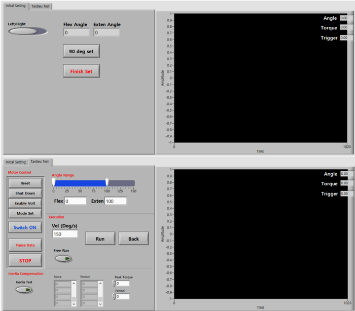
Figure a.1. GUI used in the experiment. GUI for the Initial setting step (Top) and GUI for the Tardieu test step (Bottom) Please click here to view a larger version of this figure.
- The control panel provides an interface for posture setting and robot control, and consists of two layers. The first layer is the ‘Initial Setting’ panel and second is the ‘Tardieu Test’ panel.
- The ‘Initial Setting’ panel has three buttons. The first is the ‘Left/Right’ toggle button, which is used to enter the subject’s hemiparetic side information. The second button is the ’90 deg set’ button, which is used to match the robot angle with the human anatomic angle in elbow 90 degree flexed posture. The third button is the ‘Finish set’ button to complete this step and proceed to the next layer, the ‘Tardieu Test’ panel. If you push the ‘Finish set’ button, the control panel will change to the ‘Tardieu Test’ panel.
- The ‘Tardieu Test’ panel has four sections. The ‘Motor control’ section; ‘Angle Range’ section; ‘Execution’ section; and ‘Inertia compensation’ section.
- The ‘motor control’ section has a total of seven buttons. The top four buttons with black letters are used to initialize the motor, and the ‘Switch ON’ button is used to turn on and off the motor. The ‘Data stop’ button is used to end the data communication between the real-time controller and PC. The ‘Stop’ button is used to completely stop the motor.
- The ‘Angle Range’ section shows the minimum and maximum range of the angle. The robot can only be operable in the blue region.
- The ‘Execution’ section has one number panel, one toggle button, and two buttons. The number panel is the velocity setting panel. The possible range is -1 to 200. The ‘Run’ button will actuate the motor at the given velocity. The velocity of the positive value is in the extension direction. Additionally, the ‘Back’ button is used to return the motor to the minimum angle with 5 deg/s velocity. The toggle button is the ‘Free Run’ button, which is used to change to motor control mode for manual MTS experiment.
- The ‘Inertia compensation’ section has one toggle button, two tables and two number input panels. If the toggle button is on, the robot will only move a range of 5 degrees to perturb the user to measure the inertia force. The table shows the resultant inertia force and period, as well as the two number panel is input panel for determined a peak torque value and a period value for inertia effect compensation.
- When the toggle button is on, the motor will only momentarily perturb the user if stays within the 5-degree range.
- The monitoring panel shows the state data of the robot (motor angle, interaction torque and trigger signal) in real time.
Friction removal
Note: During the manual MTS measurement, the robotic device was used only as a measurement tool. Therefore, the robot should be as transparent as possible without affecting the experiment. For this purpose, the friction of the robot should be compensated to make the robot back-drivable.
- The robotic device used in this experiment was a simple 1-DoF device, most of the resistance is caused from the gearbox of the motor.
- The friction of the gearbox can be modeled as a coulomb plus viscous friction. The figure below shows the typical form of the coulomb plus viscous friction.
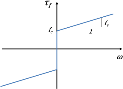
Figure a.2. General form of the coulomb plus viscous friction
- The coulomb plus viscous friction can be expressed in the following equation:

- Where τf is the total friction force generated by the motor, Tv and Tc are the viscous friction coefficient and Coulomb friction coefficient, respectively. And ω represents angular velocity.
- The viscous friction coefficient (Tv) and the coulomb friction coefficient (Tc) were determined experimentally to minimize the motor resistive torque.
- First, gradually increase the Tc value from 0, and find the value at which the manipulandum starts to move with a small force. Find the highest Tc value where there is no occurrence of motor movement without external force.
- Move the manipulandum and measure the torque and velocity. Plot the torque-velocity graph. Repeat it with increasing Tv value and select the Tv value that minimize the slope of the graph.