


Overview
Source: David Guo, College of Engineering, Technology, and Aeronautics (CETA), Southern New Hampshire University (SNHU), Manchester, New Hampshire
A Pitot-static tube is widely used for measuring unknown speeds in air flow, for example, it is used to measure airplane airspeed. By Bernoulli's principle, airspeed is directly related to variations in pressure. Therefore, the Pitot-static tube senses the stagnation pressure and static pressure. It is connected to a manometer or pressure transducer to obtain pressure readings, which allows airspeed prediction.
In this experiment, a wind tunnel is utilized to generate certain airspeeds, which is compared against Pitot-static tube predictions. The sensitivity of the Pitot-static tube due to misalignment with respect to flow direction is also investigated. This experiment will demonstrate how air flow speed is measured using a Pitot-static tube. The goal will be to predict the air flow speed based on the pressure measurements obtained.
Principles
Bernoulli's principle states that an increase in the speed of a fluid occurs simultaneously with a decrease in pressure and vice versa. Specifically, if the speed of a fluid decreases to zero, then the pressure of the fluid will increase to its maximum. This is known as the stagnation pressure or total pressure. One special form of Bernoulli's equation is as follows:
Stagnation pressure = static pressure + dynamic pressure

where the stagnation pressure, Po, is the pressure if the flow speed is reduced to zero isentropically, the static pressure, Ps, is the pressure the surrounding fluid is exerting on a given point, and the dynamic pressure, Pd, also called ram pressure, is directly related to the fluid density, ρ, and flow speed, V, for a given point. This equation only applies to incompressible flow, such as liquid flow and low-speed air flow (generally less than 100 m/s).
From the above equation, we can express flow speed, V, in terms of pressure differential and fluid density as:

In the 18th century, French engineer Henri Pitot invented the Pitot tube [1], and in the mid-19th century, French scientist Henry Darcy modified it to its modern form [2]. In the early 20th century, German aerodynamicist Ludwig Prandtl combined the static pressure measurement and Pitot tube into the Pitot-static tube, which is widely used today.
A schematic of a Pitot-static tube is shown in Figure 1. There are 2 openings in the tubes: one opening faces the flow directly to sense the stagnation pressure, and the other opening is perpendicular to the flow to measure the static pressure.

Figure 1. Schematic of a Pitot-static tube.
The pressure differential is required to determine the flow speed, which is typically measured by pressure transducers. In this experiment, a liquid column manometer is used to provide a good visual to measure the change in pressure. The pressure differential is determined as follows:

where Δh is the height difference of the manometer, ρL is the density of the liquid in the manometer, and g is the acceleration due to gravity. Combining equations 2 and 3, the flow speed is predicted by:

Procedure
1. Recording manometer pressure readings with changes in airspeed.
- Connect the two leads of the Pitot-static tube to the two ports of the manometer. The manometer should be filled with colored oil and marked as water inch graduations.
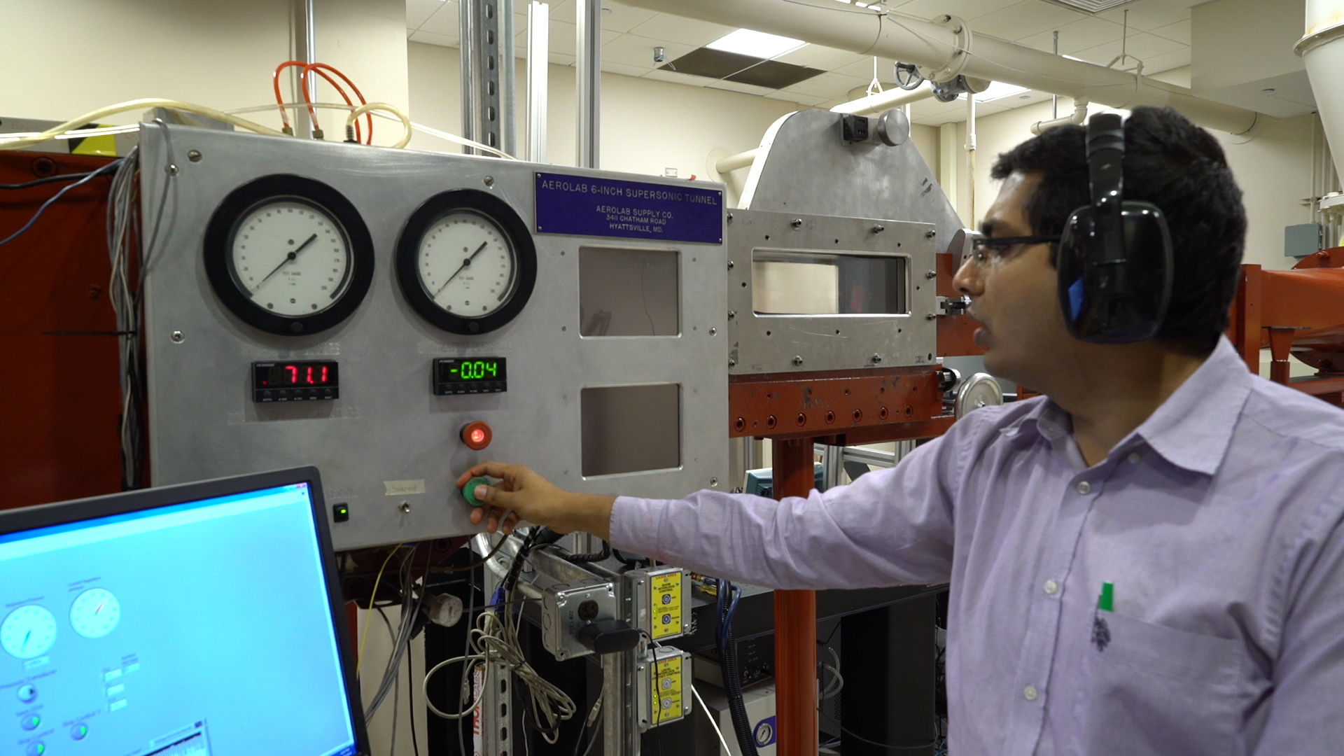
- Insert the Pitot-static tube into the threaded fitting so that the sensing head is in the center of the test section of the wind tunnel and the tube is pointing upstream. The test section should be 1 ft x 1 ft, and the wind tunnel should be able to sustain an airspeed of 140 mph.
- Use an inclinometer to adjust the Pitot-static tube to a zero-degree angle of attack.
- Run the wind tunnel at 50 mph and then record the pressure difference reading at the manometer.
- Increase the airspeed in the wind tunnel by 10 mph and record the pressure difference at the manometer.
- Repeat 1.5 until the airspeed reaches 130 mph. Record all results.
2. Investigate the accuracy of Pitot-static tubes with a positive angle of attack.
- Use the inclinometer to adjust the angle of attack to positive 4°.
- Run the wind tunnel at 100 mph, and record the pressure difference reading on the manometer.
- Increase the angle of attack by 4° increments, and repeat steps 2.1 - 2.2 up to an angle of attack of 28°. Record all results.
Unknown speeds in an airflow, for example, the air speed of an aircraft, are typically measured using a pitot-static tube. The pitot-static tube is based on Bernoulli's principle, where the increase in speed of a fluid is directly related to pressure variations.
The fluid itself exerts pressure on the surroundings, called static pressure. If the speed of the fluid is zero, the static pressure is at its maximum. This pressure is defined as the stagnation pressure, or total pressure.
As the fluid speed increases, it exerts static pressure on the surroundings as well as forces due to the velocity and density of the fluid. These forces are measured as the dynamic pressure, which is directly related to the fluid density and fluid velocity.
According to Bernoulli's principle, the stagnation pressure is equal to the sum of the static pressure and dynamic pressure. Thus, if we are interested in determining the fluid velocity, we can substitute the equation for dynamic pressure and solve for the velocity as shown. The difference between the stagnation pressure and the static pressure is called the pressure differential, delta P.
So how do we measure the stagnation and static pressures in order to determine delta P and therefore velocity? This is where the pitot-static tube comes in.
A pitot-static tube has two sets of openings. One opening is oriented directly into the airflow, while a second set of openings is perpendicular to the airflow. The opening facing the flow senses the stagnation pressure, and the openings perpendicular to the flow sense the static pressure. The pressure differential, delta P, is then measured using either a pressure transducer or a fluid manometer.
A fluid manometer is a U-shaped tube containing a liquid. At ambient pressure, where delta P equals zero, the fluid in the manometer is level at an initial height. When the manometer experiences a pressure differential, the manometer fluid height changes, and we can read the change in height as delta h.
We can then calculate the pressure differential, delta P, which is equal to the density of the liquid in the manometer, times gravitational acceleration, times delta h. Then, by substituting the calculated pressure differential into our earlier equation, we can calculate the fluid speed.
In this experiment, you will measure different wind speeds in a wind tunnel using a pitot-static tube and a fluid manometer. You will then calculate the percent error in the air speed measurements collected using a misaligned pitot-static tube.
For this experiment, you will need access to an aerodynamic wind tunnel with a test section of 1 ft by 1 ft and a maximum operating air speed of 140 mph. You will also need a pitot-static tube and a manometer filled with colored oil, but marked as water-inch graduations.
Begin by connecting the two leads of the pitot-static tube fitting to the tube ports of the manometer using soft tubing. Now, open the test section and insert the pitot-static tube into the front threaded fittings. Orient the pitot-static tube so that the sensing head is in the center of the test section, pointing upstream. Use a handheld inclinometer to measure the angle of attack, and adjust the pitot tube to reach an angle of zero.Then close the front and top of the test section.
Now, turn on the wind tunnel, set the velocity to 50 mph, and observe the height difference on the manometer. Record the height difference. Next, increase the wind speed to 60 mph and again record the height difference on the manometer.
Repeat this procedure, increasing the wind speed, in increments of 10 mph, until the wind speed reaches 130 mph. Record the height difference on the manometer for each wind speed. Then, stop the wind tunnel and open the test section.
Using the handheld inclinometer, adjust the angle of attack to positive 4°. Then, close the test section and run the wind tunnel at 100 mph. Record the manometer height difference in your notebook. Repeat this procedure for angles of attack up to 28° using 4° increments. Record the manometer height difference for each angle at 100 mph.
Now, let's take a look at how to analyze the data. First, recall that the stagnation pressure, or the pressure with zero flow speed, is equal to the static pressure plus the dynamic pressure. The dynamic pressure is directly related to the fluid density and flow speed. We can rearrange the equation to express flow speed in terms of the pressure differential and the fluid density.
The pressure differential is measured using the manometer, where the pressure differential is equal to the density of the liquid times g times the height difference in the manometer. Thus, flow velocity is predicted by the equation shown.
The air density, water density, and gravitational acceleration are known. Using the manometer height difference for each wind tunnel air speed at zero angle of attack, calculate the air speed measured by the pitot-static tube. As you can see, the percent error is quite small, showing that the pitot-static tube can predict air speed accurately, with error introduced from wind tunnel air settings, manometer readings, and other instrument errors.
Now, calculate the air speed at various angles of attack when the wind tunnel was operated at 100 mph. As you can see, the calculated air speeds are quite close to what is expected.
The percent difference is calculated by comparing the calculated air speed to the air speed measured at zero angle of attack. All differences are below 4% for the angles measured, showing that the pitot-static tube is generally insensitive to misalignment with the flow direction.
In summary, we learned how pitot-static tubes use Bernoulli's principle to determine the speed of a fluid. We then generated a range of air speeds in a wind tunnel and used a pitot-static tube to measure the different air speeds. This demonstrated the predictive sensitivity of the pitot-static tube.
Results
Representative results are shown in Table 1 and Table 2. The results of the experiment are in good agreement with the actual wind speed. The Pitot-static tube accurately predicted the airspeed with a maximum percentage of error of approximately 4.2%. This can be attributed to errors in setting the wind tunnel airspeed, errors reading the manometer and instrument errors of the Pitot-static tube.
Table 1. Calculated airspeed and error based on manometer reading at various wind tunnel speeds.
| Wind tunnel airspeed (mph) | Manometer reading (in. water) | Calculated airspeed (mph) | Percent error (%) |
| 50 | 1.1 | 48.04 | -3.93 |
| 60 | 1.6 | 57.93 | -3.45 |
| 70 | 2.15 | 67.16 | -4.06 |
| 80 | 2.8 | 76.64 | -4.20 |
| 90 | 3.6 | 86.90 | -3.45 |
| 100 | 4.4 | 96.07 | -3.93 |
| 110 | 5.4 | 106.43 | -3.25 |
| 120 | 6.5 | 116.77 | -2.69 |
| 130 | 7.8 | 127.91 | -1.61 |
Table 2. Calculated airspeed and error based on manometer reading at various angles of attach.
| Pitot-Static Tube angle of attack (°) | Manometer readings (in water) | Calculated airspeed (mph) | Percent error (%) |
| 0 | 4.4 | 96.07 | 0.00 |
| 4 | 4.5 | 97.16 | 1.13 |
| 8 | 4.5 | 97.16 | 1.13 |
| 12 | 4.6 | 98.23 | 2.25 |
| 16 | 4.65 | 98.76 | 2.80 |
| 20 | 4.7 | 99.29 | 3.35 |
| 24 | 4.55 | 97.69 | 1.69 |
| 28 | 4.3 | 94.97 | -1.14 |
In Table 2, the percentage error is compared against the zero-angle case in Table 1. The results indicate that the Pitot-static tube is insensitive to misalignment with flow directions. The highest discrepancy occurred at an angle of attack of about 20°. A 3.35% error was obtained with respect to the zero angle reading. As the angle of attack increased, both the stagnation and static pressure measurements decreased. The two pressure readings tend to compensate each other so that the tube yields velocity readings that are accurate to 3 - 4% for angles of attack up to 30°. This is the chief advantage of the Prandtl design over other types of Pitot tubes.
Applications and Summary
Airspeed information is critical to aviation applications, such as for aircraft and drones. A Pitot-static tube is typically connected to a mechanical meter to show the airspeed at the front panel in the cockpit. For commercial aircraft, it is also connected to the onboard flight control system.
Errors in pitot-static system readings can be extremely dangerous. There are typically 1 or 2 redundant Pitot-static systems for commercial aircraft. To prevent ice buildup, the Pitot tube is heated during flight. Many commercial airline incidents and accidents have been traced to a failure of the Pitot-static system. For example, in 2008 Air Caraibes reported two incidents of Pitot tube icing malfunctions on its A330s [3].
In industry, the airspeed in duct and tubing can be measured with Pitot tubes where an anemometer or other flow meters would be difficult to install. The Pitot tube can be easily inserted through a small hole in the duct.
In this demonstration, the use of Pitot-static tubes was examined in a wind tunnel and the measurements were used to predict airspeed in the wind tunnel. The results predicted by the Pitot-static tube correlated well with the wind tunnel settings. The sensitivity of possible misalignment of the Pitot-static tube was also investigated and it was concluded that the Pitot-static tube is not particularly sensitive to misalignment up to and angle of attack of 28°.
References
- Pitot, Henri (1732). "Description d'une machine pour mesurer la vitesse des eaux courantes et le sillage des vaisseaux". Histoire de l'Académie royale des sciences avec les mémoires de mathématique et de physique tirés des registres de cette Académie: 363–376. Retrieved 2009-06-19.
- Darcy, Henry (1858). "Note relative à quelques modifications à introduire dans le tube de Pitot" (PDF). Annales des Ponts et Chaussées: 351–359. Retrieved 2009-07-31.
- Daly, Kieran (11 June 2009). "Air Caraibes Atlantique memo details pitot icing incidents". Flight International. Retrieved 19 February 2012.