


Overview
Source: Shreyas Narsipur, Mechanical and Aerospace Engineering, North Carolina State University, Raleigh, NC
Fluid pressure is an important flow characteristic that is required to determine the aerodynamics of a system. One of the oldest and still existing pressure measurement systems is the manometer due to its accuracy and simplicity of operation. The manometer is generally a U-shaped glass tube that is partially filled with liquid, as shown in Figure 1. The U-tube manometer requires no calibration because it does not have any moving parts, and its measurements are functions of gravity and the liquid's density. Therefore, the manometer is a simple and accurate measurement system.
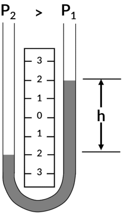
Figure 1. Schematic of a U-tube manometer.
Real-time pressure measurements are obtained in aircraft by connecting the stagnation and static pressure ports of a pitot-static probe, a device that is commonly used to measure fluid flow pressure, to the ports of a pressure measurement device. This allows pilots to obtain existing flight conditions and to warn them if any changes to the flight conditions occur. While manometers provide very accurate pressure readings, they are inherently bulky. A more realistic solution is needed to measure aircraft pressures, as one of the primary design objectives is to keep the overall aircraft weight as low as possible. Today, electromechanical pressure transducers, which convert the applied pressure to an electric signal, are widely used for pressure sensing applications on aircraft because they are small, lightweight, and can be placed almost anywhere in the airframe. The above characteristics not only help reduce weight but also reduce the amount of tubing required to connect the pitot-static probe to the transducer, thereby decreasing the data response time. Additionally, in experimental aircraft flight testing, miniature pressure transducers come in handy as they allow researchers to maximize pressure data collection without significantly adding to the weight of the aircraft. While different types of pressure transducers with varying measurement techniques exist, one of the more common types of transducer is the capacitive pressure transducer. As transducers are capable of only sending signals in terms of voltage and current, calibration of the transducer is required to relate the strength of a particular signal to the pressure that causes the transducer to generate the signal. The final curve fit that relates the transducer current or voltage to a physical measurement, in our case pressure, is commonly referred to as the transducer calibration curve.
In this experiment, a pitot-static probe is placed in a subsonic wind tunnel with the stagnation and static pressure ports connected to the total and static ports of both the U-tube manometer and the pressure transducer. The wind tunnel is then run at different dynamic pressure settings, and the corresponding pressure reading from the U-tube manometer, and current readings produced by the transducer are recorded. This data is then used to generate calibration curves for the pressure transducer.
Principles
In order to measure the dynamic pressure, each leg of the U-tube manometer is connected to unknown pressures from the static and total pressure ports of the pitot-static tube. The resulting difference is given by the following equation:
 (1)
(1)
which translates to a difference in column height on the U-tube manometer. This difference in pressures, or dynamic pressure, can be calculated using the expression:
 (2)
(2)
where ρwater is the density of water (the fluid in the U-tube manometer), g is the acceleration due to gravity, and hmanometer is the difference in column heights in the U-tube manometer. In some cases, the manometer can have an offset due to insufficient amount of fluid in the chamber and the offset in height, hoff, will have to be accounted for in the above equation as:
 (3)
(3)
The pressure transducer is based on the working principle of a capacitor, which consists of two conductive plates separated by an insulator (Figure 2).

Figure 2. Schematics of a capacitor (A) and a capacitance pressure transducer (B).
Capacitance is measured using the equation:
 (4)
(4)
where μ is the dielectric constant of the material, A is the area of the plates, and d is the spacing between the plates. In a capacitance pressure transducer, one of the conductive plates is replaced by a flexible conducting diaphragm, as shown in Figure 2. When pressure is applied, the diaphragm deflects, which causes a change in d, thereby leading to a change in capacitance. The electronics in the transducer are calibrated to generate specific voltage changes for corresponding changes in capacitance, which in turn can be used to measure the current for a given applied pressure.
Subscription Required. Please recommend JoVE to your librarian.
Procedure
1. Pressure Transducer Calibration
In this demonstration, a subsonic wind tunnel with a 2.6 ft x 3.7 ft test section and maximum dynamic pressure setting of 25 psf was used. A pre-calibrated pressure transducer was used to set the dynamic pressure in the wind tunnel test section, and a differential U-tube manometer with colored water and scale was used to measure fluid height (Figure 3). A differential pressure transducer (Figure 4), standard voltage supply (to power the transducer), and multimeter (to read the output current from the transducer) were also used, shown in Figure 5.

Figure 3. Differential pressure U-tube manometer.

Figure 4. Differential pressure transducer.

Figure 5. Power supply (left) and multimeter (right).
- Mount a standard pitot-static tube (Figure 6) from the top of the wind tunnel using a vertical sting mount. Ensure that the probe is at the center of the test section and is aligned in the direction of the flow with the primary port facing directly into the flow.

Figure 6. Pitot-static tube.
- Align the top of the manometer fluid to the double O-ring marker on the glass tube. If the reading on the main scale (in brown, Figure 3) does not correspond to zero, choose a different reference point, align the manometer fluid to the new reference, and record the offset in height (hoff).
- Connect the stagnation and static pressure outlets on the pitot-static tube to the corresponding ports on the U-tube manometer and the pressure transducer using flexible plastic tubing and T-channel connectors. Note that the pressure transducer can be mounted on any flat vertical surface as long as it is aligned in accordance with Figure 4.
- Secure the wind tunnel doors and switch-on all the systems.
- Take the reading for the no-air flow condition (zero reading).
- Start the wind tunnel and set the dynamic pressure in the test section to 1psf.
- Record the data corresponding to Table 1.
- Increase the dynamic pressure setting in the wind-tunnel in steps of 1psf up to a maximum setting of 20psf and repeat step 1.7 at each dynamic pressure setting.
- To check for transducer hysteresis, decrease the dynamic pressure in steps of 1psf down to 0psf and repeat step 1.7 at each dynamic pressure setting.
- On completion of the test, shut down all systems.
Table 1. Data collected for the pressure calibration experiment
| Ptransducer (psf) |
hmanometer (in) |
Itransducer (mA) |
| WT transducer | manometer | multimeter |
All airplanes use pressure measurements in order to make real-time calculations of wind speed. In an airplane, these pressure measurements are obtained using a pitot-static tube.
A pitot-static tube has openings that measure the stagnation pressure and the static pressure. Recall that stagnation pressure is the sum total of the static pressure and the dynamic pressure, so the pitot-static tube is used to measure the dynamic pressure and therefore the flow velocity.One method to correlate wind speed to pressure using the pitot-static tube is by using a fluid manometer.
A fluid manometer is generally a U-shaped glass tube that is partially filled with liquid. One arm of the manometer is connected to the stagnation pressure port on the pitot-static tube, and the other to the static pressure port. In stagnant air, where this is no difference between the static pressure and stagnation pressure, the manometer fluid height difference is zero.
When the manometer experiences a pressure differential, it is visualized by a change in fluid height. The pressure differential, or dynamic pressure, is calculated from delta H using this equation. Here, rho L is the density of fluid in the manometer and G is gravitational acceleration. This relationship is used to calculate the wind speed by substituting it into the velocity equation. We can then solve for the free-stream velocity, V infinity, using the free-stream density, rho infinity.
However, fluid manometers are bulky, and require manual reading onboard the aircraft. Thus, a more convenient method to measure the pressure differential is to use a pressure transducer in place of the manometer. This enables us to convert the pressure differential into an electrical signal.
A capacitance pressure transducer is based on the working principle of a capacitor, which consists of two conductive plates separated by an insulator. Capacitance is measured by the following equation, where mu is the dielectric constant of the insulator material, A is the area of plates, and D is the spacing between the plates.
To make the capacitance pressure transducer, one of the conductive plates is replaced by a flexible conducting diaphragm. When pressure is applied, the diaphragm deflects causing a change in the spacing between the plates D, resulting in a change in capacitance. The electronics in the transducer are calibrated to generate specific current changes for corresponding deviations in capacitance. Thus, a current reading corresponds to a given applied pressure.
Like the manometer, the pressure transducer is connected to the pitot-tube and is calibrated in a wind tunnel with known wind speeds. This enables us to generate a mathematical relationship between current and pressure, and by extension, current and wind speed.
In this lab demonstration, we will use a pitot-static tube in a wind tunnel connected to a pressure transducer. We will then calibrate the pressure transducer at various wind speeds and determine the relationship between voltage and speed.
For this experiment, you'll need to use a wind tunnel with its own calibrated pressure transducer and ability to reach a dynamic pressure of 25 psf. You will also use a standard pitot-static tube and a differential U-tube manometer with colored water to calibrate this differential pressure transducer.
To begin, mount the pitot-static tube inside of the wind tunnel on the top of the test section using a vertical sting mount. Ensure that the probe is at the center of the test section. Align the pitot tube with the direction of flow, so that the primary port faces directly into the air flow.
Next, align the top of the manometer fluid to the double O-ring marker on the glass tube. If the reading on the main scale does not correspond to zero, align the fluid to a different reference point, and record the offset height.
Use a T-connector to split the flow from one tube to two, then connect the stagnation and static pressure outlets on the pitot-static tube, to the corresponding ports on the U-tube manometer. Mount the pressure transducer outside of the wind tunnel test section on a vertical surface. Set up a standard voltage supply to power the pressure transducer and a multimeter to read the output current. Then, connect the stagnation and static pressure outlets to the corresponding pressure ports on the transducer.
Now, secure the wind tunnel doors and switch on all of the systems. Then, take readings of the wind tunnel transducer pressure, the manometer height, and the differential pressure transducer current. Record the measurements for the no airflow condition as the base line zero reading. Now turn on the wind tunnel, and set the dynamic pressure in the test section to one psf.
Once the flow has stabilized, record the transducer pressure, the manometer height difference, and transducer current. Increase the dynamic pressure setting in the wind tunnel in steps of one psf, up to a maximum setting of 20 psf, recording the data at each step. In order to check for hysteresis, decrease the dynamic pressure in steps of one psf, back down to zero psf, again recording data at each step. When all of the measurements have been collected, shut down all systems.
Now, lets take a look at the results. First, we look at a plot of the manometer height readings with increasing and decreasing dynamic pressure. Two measurements are shown here for each trace. One is the actual manometer reading, and the other has been corrected with the offset height of 0.8 inches. We can calculate the manometer pressure from the manometer height, using the simple equation shown. Here, we use the density of the liquid in the manometer, which is in this case water, gravitational acceleration, and the manometer offset and height measurements.
Now that we have calculated the pressure from the manometer reading, we'll plot it against the pressure transducer current readings. To obtain the calibration curve for the pressure transducer, we'll fit the increasing and decreasing data separately, resulting in two linear best fit equations.
However, we see that the increasing and decreasing data line up. So we can conclude that the pressure transducer does not exhibit hysteresis. Thus, we can simplify to a single calibration equation, thereby enabling us to measure pressure using the current reading from pressure transducer, rather than the bulky fluid manometer. By connecting the pitot-static probe to the calibrated transducer, we can directly measure the dynamic pressure and therefore, wind speeds.
In summary, we learned how pressure differentials measured during flight correlate to flow velocity. We then calibrated a pressure transducer by subjecting a pitot-static tube to varying wind speeds, and determined the relationship between voltage and wind speed.
Subscription Required. Please recommend JoVE to your librarian.
Results
The following constants were used in the analysis: water density, ρwater: 61.04 lb/ft3; acceleration due to gravity, g: 32.15 ft/s2; and manometer off-set, hoff = 0.8 in. The variation in manometer data for increasing and decreasing dynamic pressures (with and without correcting for the instrument off-set) is shown in Figure 7. Figure 8 shows a plot of the transducer current readings against the manometer pressure, which was calculated using Equation 3.
In order to obtain the calibration curve for the pressure transducer, two linear curves are fitted through the increasing and decreasing data points, respectively. The corresponding linear fit equations are:
 (5)
(5)
 (6)
(6)
The equations for the increasing and decreasing curves are almost similar, and the two curves align with each other, as observed in Figure 8. Therefore, it can be deduced that the pressure transducer does not have any hysteresis. A single calibration equation relating the current to the pressure (Equations 5 or 6) can be used for the transducer, thereby removing the necessity of using the bulky U-tube manometer system for all future pressure measurements.

Figure 7. Variation of manometer fluid height with wind tunnel dynamic pressure. Please click here to view a larger version of this figure.

Figure 8. Calibration curves for the pressure transducer. Please click here to view a larger version of this figure.
Subscription Required. Please recommend JoVE to your librarian.
Applications and Summary
Electromechanical transducers are popular replacements for some of the bulkier measurement systems. However, transducers need to be calibrated regularly using standardized measuring devices in order to be effective experimental tools. In this experiment, an off-the-shelf capacitive type electromechanical pressure transducer was calibrated by comparing the current signals generated by the transducer for a range of dynamic pressure conditions in a subsonic wind tunnel to the pressure measurements from a U-tube manometer. Results showed that a linear relationship exists between the transducer's current signal and pressure with negligible sensor hysteresis. A single calibration equation relating the transducer current output to pressure was obtained.
Modern electromechanical measurement systems provide a path to automating experimental data acquisition and can be used in real-time static and dynamic systems for data monitoring and analysis. However, proper calibration practices, like the one demonstrated in this experiment, are necessary to help users obtain accurate and repeatable data using said sensors.
Subscription Required. Please recommend JoVE to your librarian.