

Summary
A novel microfluidic system has been developed using the phenomenon of passive pumping and a user controlled fluid delivery system. This microfluidic system has the potential to be used in a wide variety of biological applications given its low cost, ease of use, volumetric precision, high speed, repeatability and automation.
Abstract
A novel microfluidic system has been developed that uses the phenomenon of passive pumping along with a user controlled droplet based fluid delivery system. Passive pumping is the phenomenon by which surface tension induced pressure differences drive fluid movement in closed channels. The automated fluid delivery system consists of a set of voltage controlled valves with micro-nozzles connected to a fluid reservoir and a control system. These voltage controlled valves offer a volumetrically precise way to deliver fluid droplets to the inlet of a microfluidic device in a high frequency manner. Based on the dimensions demonstrated in the current study example, the system is capable of flowing 4 milliliters per minute (through a 2.2mm by 260um cross-sectional channel). Based on these same channel dimensions, fluid exchange of a point inside the channel can be achieved in as little as eight milliseconds. It is observed that there is interplay between momentum of the system (imparted by a combination of the droplets created by the valves and the fluid velocity in the channel), and the surface tension of the liquid. Where momentum provides velocity to the fluid flow (or vice-versa), equilibration of surface tension at the inlet provides a sudden stop to any flow. This sudden stop allows the user to control the flow characteristics of the channel and opens the door for a variety of biological applications, ranging anywhere from reagent delivery to drug-cell studies. It is also observed that when nozzles are aimed at the inlet at shallow angles, the droplet momentum can cause additional interesting fluid phenomena, such as mixing of multiple droplets in the inlet.Protocol
In this report we demonstrate a fluid delivery method that uses small droplet surface tension to pump a desired volume through a microfluidic channel in order to achieve a number of different fluid phenomena. For example, the user may wish to flow a single fluid as fast as possible, or deliver multiple fluids in rapid succession to create specific fluidic patterns. In order to do this, the user must first have an application built around a microfluidic device. The microflluidic device does not need to be bonded, but should be made from a hydrophilic material. Therfore, the method can be utilized with almost any microfluidic device, with performance largely dictated by the geometrical constraints of the microfluidic channel. To help navigate the geometrical constraints of this method, an introduction to the relevant numerical analysis is presented first.
- Analytical Methods: According to the Laplace Law and the Washburn Law [1], one can relate the flow rate within a microfluidic channel to its dimensions and the properties of the flowing liquid as seen in equation (1),
 (1)
(1)
where ΔP is the pressure difference between the inlet and the outlet, γ is the liquid surface tension, R is the inlet drop radius, Q is the flow rate and K is the fluidic resistance as described by equation (2),
 (2)
(2)
where η is the liquid viscosity, L0 is the channel length, h is the channel height, w is the channel width, λ=w/h and g (λ) =1.5 if λ >4.45 or
if λ < 4.45. Substituting equation (2) into equation (1), always assuming that h<w and solving for Q, one obtains equation (3),
(3)
The same analysis can be done for the velocity of the fluid inside a channel by knowing that Q=VA, where V is the fluid average velocity and A is the cross-sectional area or hw. Plugging these into equation (3) you come up with equation (4),
(4)
An important mechanical concept that is frequently applied in microfluidic biology is shear stress, which relates to flow rate and velocity by equation (5),
(5)
Knowing the relationship between flow rate, velocity and their physical implications as a function of channel dimensions and fluid properties is crucial in the design of a microfluidic device for a given purpose. Once a device is created, the user must then calibrate the fluid delivery system to achieve the desired flow characteristics within the device. - Steps in Setting up and Calibrating Delivery System:
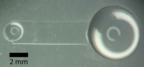
- Create microfluidic device via soft-lithography technique using polydimethylsiloxane (PDMS, Sylgard 184, Dow Corning) [2]. There are number JoVE articles that illustrate methods for making PDMS microfluidic devices [5]. For this demonstration, we have chosen a simple straight channel, with dimensions as follows: 2.2mm width, 10mm length and 260um height. The inlet and outlet diameters are 1.8mm and 5.1mm respectively (figure 1). Reversibly attach PDMS device to glass slide by pressing it onto a glass slide (or other suitable substrate) and squeezing out any air bubbles [5]. A reversible attachment allows the device to be re-used multiple times. The method can also be used with permanently bonded devices, but it not required.
- Fill device with liquid. The hydrophobic nature of PDMS and the hydrophilic nature of glass help move a drop that is placed at the inlet, or outlet, into the channel. If the drop of liquid does not want to go into the channel by itself or if bubbles move into the channel, the user may put a drop of liquid at the inlet, or outlet, and use a pipette at the opposite end to suck the liquid through the channel. Another method of helping the liquid move into the channel is by separating the PDMS device from the glass slide and gently cleaning the PDMS device and the glass slide with ethanol. This returns to the PDMS and the glass slide their hydrophobic and hydrophilic natures, respectively, which may have been weakened with time and use.
- After filling device with liquid, place a small drop on the inlet and a bigger drop on the outlet. Make sure passive pumping is happening by watching the small drop at the inlet collapse and observing fluid flow towards the outlet. Again, make sure there are no bubbles inside the channel.
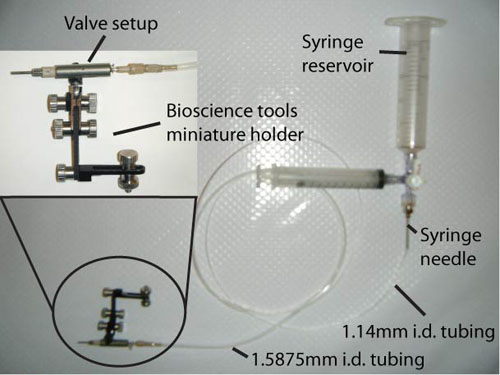
- Using The Lee Company’s [3] VHS micro dispensing starting kit, put together one or more valves (valve setup in figure 2) consisting of the Lee VHS M/2 24 Volt Valve, a 0.062 MINSTAC Nozzles with orifice size of 0.0100", the Lee 0.062 Minstac to Soft Tube Adapter, the Lee Spike and Hold Driver (for user control, not shown) and the Lead Wire Assembly (connecting the valve to the Spike and Hold Driver, not shown).
- An easy way to hold the valves is by using the Bioscience tools miniature holders (figure 2) [4]. These provide a way to precisely aim and hold the valve at a certain position during experimentation by gluing the valve to one end of the holder and using a magnetic base (not shown) on the other side.
- Make a reservoir system to be placed a few feet above the PDMS microfluidic device (in our case we used ¾ ounce syringes open to the ambient, see figure 2). The reservoir provides a pressure head to drive the nozzles, with the pressure being proportional to the height of the reservoir. Alternatively the nozzle valves can be pressurized by any number of different means (ie, compressed gas). Attach a syringe needle to the syringe. A typical syringe needle will easily attach into 1.14 mm inner diameter tubing. The 1.14 mm tubing will then easily attach into 1.58 mm (1/16”) inner diameter tubing which then itself connects to the “Soft Tube Adapter” of the valve. To prevent leakage of liquid in the 1.14 mm to 1.58 mm tubing connection, one may use PDMS as a sealant. Now that there is a line between the syringe needle and the Lee Co. valve, fill syringe reservoirs with liquid. An extra syringe and a valve may be used to help in the purging process (shown but not labeled in figure 2). Place a magnet to the side of the valve; this is how these valves are purged (they are normally closed solenoid valves), and watch liquid start flowing from the reservoir through the valve and out the 0.0100’’ nozzle.
- Calibrate system by choosing a valve open time (open time is the time that the valve allows fluid to pass on a per pulse basis) and frequency (number of pulses per second). Activate one valve for a chosen period (a minute or so, just remember the total run time). Weigh the fluid that was delivered from the valve. Knowing the total run time, frequency and per-pulse open time, calculate the grams per millisecond shot out from the valve. This “grams per millisecond” value will allow you to choose an open time for any desired volume the user may want to be delivered from the valve.
 (1)
(1) (2)
(2)


Example: System activated for a minute (60 seconds). The frequency was 15 Hz (15 pulses in one second). The per-pulse open time was 20 milliseconds (ms).
(20ms)(15Hz)(60s)=18000ms.
This means that out of the 60,000 ms in one minute, the valve was actually open for 18,000ms.
Let’s assume the volume of fluid delivered weighed 5 grams. Then,
5 grams / 18000 ms = 2.78e-4 grams/ms.
In the case of water, with its density being one gram per milliliter (mL),
2.78e-4 grams/ms = 2.78e-4 mL/ms.
After calibration, the volume of a drop is dependent on the open time. For example, with an open time of 20ms, and all the parameters remaining the same as in the previous example,
(2.78e-4 mL/ms)(20 ms) = 5.56e-3 mL = 5.56 μL.
To find the open time y needed to make a drop of x microliter (μL) volume,
(x μL) / [(2.78e-4 mL/ms)(1000 μL/mL)] = y ms
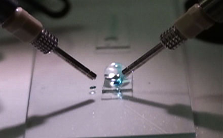
8) Aim one or more nozzles to the inlet of the PDMS device (figure 3). Having calibrated the system, calculate the volume coming out of each valve, based on microfluidic device dimensions. For high speed passive pumping (to obtain maximum flow rate), calculate the inlet drop volume necessary to create an inlet drop which possesses a 90deg contact angle with inlet surface [2]. For packet creation, calculate valve frequency and open times and the valve timings necessary to activate two valves in sequence. As seen in Figure 3, the two nozzles can be pointed at the inlet. This can extended to multiple nozzles, all aimed at the channel inlet.
Representative Results:
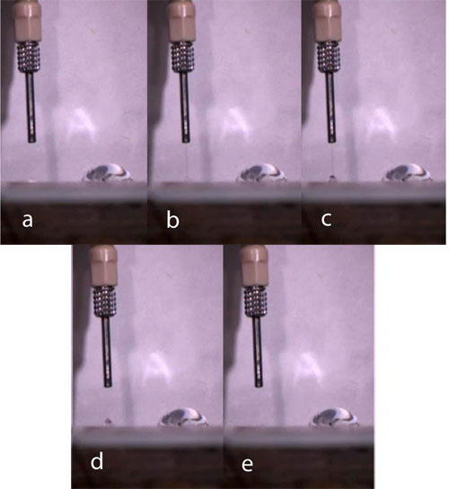
When properly calibrated, with valve open times correctly calculated and the nozzles properly aimed at the inlet, the user should be able to see flow passively pumped (figure 4). A burst of liquid should come out of the valve and reach the inlet. As liquid reaches the inlet, there is an instant collapse of the inlet drop into the channel, towards the outlet. Liquid within the channel moves only during the collapse of an inlet drop. Complete fluid movement within the channel stops at the end of the drop collapse, providing for instantaneous fluid stop and well defined fluidic boundaries (in the case that the user is flowing multiple liquids). The duration of drop collapse depends on the inlet port radius and the volume of the inlet drop [1]. In our experimental setup and design, inlet drop collapse occurs in a matter of a few milliseconds.

Figure 1. PDMS microfluidic device with one inlet, left, and one outlet, right. Please click here to see a larger version of figure 1.

Figure 2. Reservoir system and valve setup. Please click here to see a larger version of figure 2.

Figure 3. Two valves, both aimed at a single inlet of a microfluidic device. Please click here to see a larger version of figure 3.

Figure 4. Time-step sequence (33 millisecond) of inlet drop collapse following fluid ejection from a valve. Please click here to see a larger version of figure 4.
Subscription Required. Please recommend JoVE to your librarian.
Discussion
- For high speed passive pumping, if the right combination of frequency and per pulse volume (due to the correct open time) is chosen, user should see what seems to be a static drop or shell at inlet and a very fast flow rate inside channel. If overflow occurs, the open time and/or the frequency are too high.
- To detect momentum/surface tension interactions, the user should pump one pulse at a time and observe the intra-channel environment while pulse is occurring (from beginning to end). It is recommended by the authors to use fluorescent beads to provide an accurate depiction of intra-channel fluid behavior. Upon the collapse of a single drop in the inlet the user should see, inside the channel, movement of beads towards the outlet. Using a high speed camera, the user can note that beads move forward (towards outlet) a certain distance and then suffer from a small backflow before coming to a complete and sudden stop. If the inlet drop is observed at the same time as the intra-channel medium, the user should note that the small backflow of beads corresponds to a small but sudden rebound of the inlet drop. This suggests that there exists a momentum/surface tension relationship in the fluid being passively pumped, primarily in the fluid drops delivered at the inlet. The momentum is either momentum imparted by the valves to the inlet drop and/or momentum created by the drop collapsing. Either way, this momentum is transferred into intra-channel fluid velocity. Momentum and its implications is something that has to be studied more in the future and may have numerous potential applications.
- If the nozzles are aimed at the inlets at a very shallow angle, momentum of the droplets can result in a number of various changes in the droplet collapse phenomena. For example, if dyes are used in the liquid, the user may observe a swirling of the liquid at the inlet and as a result see a mixture of dyes rather than single dye colors being pumped into the channel, suggesting that fluids at the inlet have been mixed during collapse. In some cases this can be problematic in getting accurate fluid exchanges, but in other applications it may prove to be beneficial to promoting mixing of fluids. In cases of very extreme shallow angles of the nozzles, combined with droplets of high velocity, the user may observe the droplets ‘bouncing off’ of the inlet, as the momentum of the drop becomes too great to allow it to coalesce with the inlet drop.
- When passively pumping liquid in a microfluidic device, the fluid velocity is a function of the device dimensions and fluid properties as shown in equations (1) through (4). The pressure provided by a drop of liquid is inversely proportional to the drop radius, i.e. a greater drop radius provides less driving pressure. If the channel width and height grow proportional with each other, then the greater these dimensions are, the greater the velocity can be. However, there comes a point where great channel dimensions take a microfluidic device into the macrofluidic world where the boundary of laminar and turbulent flow meet. In that region of Reynolds numbers these equations no longer work. So to keep the system in the region of laminar flow, one of the dimensions can become bigger (channel width) while the other is left constant somewhere in the micro-scale (channel height). The inlet port may be left as a constant or may scale with the channel width. With these assumptions in mind, if the inlet port scales with channel width, there will come a point where the pressure provided by the inlet fluid drop is less than the fluidic resistance provided by an increase in channel width. When this point is reached, a reduction in fluidic velocity will be seen. If the inlet port is left constant and the width is made greater, then the velocity will become greater until the point at which the fluidic resistance gained with an increase in channel width overpowers the flow rate advantage provided by an increase in cross-sectional area. There is a delicate balance between the channel and inlet port dimensions and the surface tension of the fluid drop. The greatest velocity for a channel can be achieved when the channel height is equal to the channel width, i.e. a square cross-sectional area. A square cross-sectional area is the dimension that maximizes volume flow rate while minimizing surface contact area, i.e. greatest flow rate with least fluidic resistance.
- Different biological applications likely require different microfluidic device designs. The benefit of passive pumping is that as long as there is an inlet and an outlet, passive pumping will work. It is also very convenient in that it does not require the microfluidic device to be bonded to its substrate. This allows it to be used with almost any type of substrate. To avoid human error or high costs, the authors use The Lee Company’s VHS starting kit along with LabVIEW (National Instruments). This system allows the user to control volumetric flows and delivery times while ensuring a precise and automated fluid delivery method. Multiple inlets and outlets may also be used, but control of the direction of flow is more difficult in these scenarios.
Subscription Required. Please recommend JoVE to your librarian.
Acknowledgments
Funding was provided by the Wisconsin Institute of Discovery.
Materials
| Name | Company | Catalog Number | Comments |
| Sylgard 184 Silicone elastometer base | Dow Corning | MSDS No.: 01064291 | |
| Sylgard 184 Silicone elastometer curing agent | Dow Corning | MSDS No.: 01064291 | |
| VHS Microdispensing Starting kit | The Lee Company | IKTX0322000A | |
| Miniature Holders | Bioscience Tools | MH-2 | |
| LabVIEW | National Instruments | Control System | |
| 1.14mm I.D. tubing | Scientific Commodities Inc. | BB31695-PE/7 | |
| 1.57mm I.D. tubing | Scientific Commodities Inc. | BB31695-PE/10 | |
| 20 mL BD™ Luer-Lok Tip Syringe, non-sterile | BD Biosciences | 301032 | |
References
- Berthier, E., Beebe, D. J. Flow rate analysis of a tension driven passive micropump. Lab Chip. 7, 1475-1478 (2007).
- Duffy, D. C., McDonald, J. C., Schueller, O. J. A., Whitesides, G. M. Rapid Prototyping of Microfluidic Systems in Poly(dimethylsiloxane). Anal. Chem. 70, 4974-4984 (1998).
- Harris, J., Lee, H., Vahidi, B., Tu, C., Cribbs, D., Cotman, C., NL, J. eon Non-plasma Bonding of PDMS for Inexpensive Fabrication of Microfluidic Devices. J Vis Exp. (9), (2007).
- Walker, G. M., Beebe, D. J. A passive pumping method for microfluidic devices. Lab Chip. 2 (3), 131-134 (2002).
