11.8
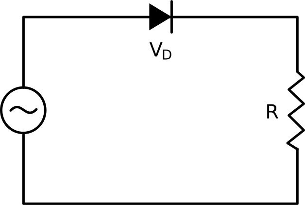
半波整流器は、交流 (AC) 電圧を一方向の電圧に変換するように設計された、電子機器の基本的な回路です。最も単純な形式のダイオード整流を利用し、回路は負荷抵抗器と AC 電源に直列に接続された単一のダイオードで構成されます。
半波整流器の動作は、ダイオードが電流を一方向にのみ流すという原理に基づいて…
ダイオード整流回路は、半波または全波構成を使用してAC電圧を単方向DC電圧に変換します。
ダイオード、抵抗、および入力正弦波信号を直列に組み合わせた半波整流回路を考えてみましょう。
入力信号の正の半サイクル中に、電圧がダイオードの電圧降下を超えるか等しいと、電圧は順方向にバイアスされ、電流が流れるようになります。
次に、出力電圧は、入力電圧からダイオードの電圧降下を差し引くことによって決定されます。
逆に、負の半サイクルでは、入力電圧はダイオードの電圧降下よりも低く、ダイオードは非導電性のままであるため、出力電圧はゼロになります。
入力電圧が平均値ゼロで極性が変化するにもかかわらず、出力は整流により一貫した平均値で単方向のままです。
ピーク逆電圧は、ダイオードが損傷なく耐えることができる最大逆電圧を表します。
半波整流器では、入力電圧が負の方向にピークに達する負の半サイクル中にこれが発生します。
したがって、逆電圧のピークは入力電圧のピークと等しくなりますが、極性は逆になります。
View the full transcript and gain access to JoVE Core videos
Q1: How does a half-wave rectifier convert AC voltage to DC?
A half-wave rectifier uses a single diode to convert alternating current into unidirectional voltage. During positive half-cycles, the diode becomes forward-biased when input voltage exceeds its threshold, allowing current flow and producing output voltage. During negative half-cycles, the diode remains reverse-biased and non-conductive, resulting in zero output. This creates a pulsating DC that flows only during positive input cycles.
Q2: What is the relationship between input and output voltage in a half-wave rectifier?
The output voltage in a half-wave rectifier equals the input voltage minus the diode's forward voltage drop during conduction. When the diode conducts during positive half-cycles, this voltage difference appears across the load resistor. During negative half-cycles, the output voltage drops to zero because the diode blocks current flow, resulting in no voltage across the load.
Q3: What is peak inverse voltage and why does it matter in rectifier circuits?
Peak inverse voltage (PIV) is the maximum reverse voltage a diode can withstand without breakdown. In a half-wave rectifier, PIV occurs during negative half-cycles when input voltage reaches its peak in the negative direction, equaling the input voltage peak with reversed polarity. Selecting a diode with adequate PIV rating prevents damage and ensures circuit longevity and reliability.
Q4: Why does the diode conduct during positive half-cycles but not negative ones?
During positive half-cycles, input voltage exceeds the diode's threshold voltage, creating forward-bias conditions that allow current flow. During negative half-cycles, input voltage falls below the diode's potential barrier, establishing reverse-bias conditions where the diode becomes non-conductive. This directional behavior is fundamental to how diodes rectify AC signals into unidirectional current.
Q5: What circuit components are required for a basic half-wave rectifier?
A basic half-wave rectifier requires three essential components: a diode, a load resistor, and an AC power source connected in series. The diode controls current direction, the resistor provides the load path, and the AC source supplies the alternating input signal. This simple configuration forms the foundation of rectification circuits used in power supply applications.
Q6: How does a half-wave rectifier produce a consistent average DC value from a zero-average AC signal?
Although the input AC signal has an average value of zero due to equal positive and negative cycles, the half-wave rectifier blocks negative half-cycles entirely. This asymmetry produces a pulsating DC output that flows only during positive input cycles, resulting in a consistent positive average value. The rectification process effectively removes the negative portion of the waveform.
Q7: How does a half-wave rectifier compare to a full-wave rectifier in terms of output?
A half-wave rectifier conducts during only positive half-cycles, producing output pulses at half the input frequency with lower average DC value. A full-wave rectifier utilizes both positive and negative half-cycles, delivering output pulses at twice the frequency with higher average DC value and smoother waveform. Full-wave configurations provide more efficient power conversion and reduced ripple.