11.9
全波整流器は交流 (AC) を直流 (DC) に変換するデバイスで、半波整流器よりも効率的です。通常、センタータップ付きトランス、2 つのダイオード、および負荷抵抗器が含まれます。トランスの二次巻線は、全波整流の重要な要素である、反対極性の 2 つの等しい電圧を提供するために分割されます。
全波整流…
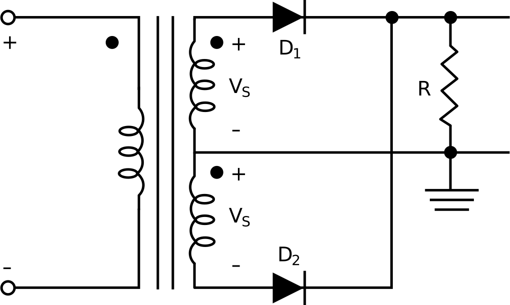
センタータップ付きトランス、センタータップ構成の2つのダイオード、および負荷抵抗で構成される全波整流回路を考えてみましょう。
トランスの二次巻線は、二次巻線の2つの半分にわたって反対の極性を持つ2つの等しい入力電圧を供給します。
入力信号の正の半サイクル中、電圧がダイオードの順方向電圧降下を超えるか等しい場合、ダイオードD1は導通し、D2は逆バイアスされます。出力波形は半波整流器の波形に似ています。
逆に、負の半サイクルで入力電圧がダイオードの順方向電圧降下よりも低い場合、ダイオードD1は切断され、D2は導通します。ここでも、出力波形は半波整流器の波形を反映しています。
抵抗を流れる電流は一貫して同じ方向に流れ、ユニポーラ出力になります。
全波整流器の整流効率の向上により、電源、バッテリー充電器、オーディオアンプ、および信号処理での使用が可能になります。
逆電圧のピークは、ピーク入力電圧からダイオードの順方向電圧降下を差し引いた値の2倍で、半波整流器の場合の約2倍です。
View the full transcript and gain access to JoVE Core videos
Q1: How does a full-wave rectifier convert AC to DC?
A full-wave rectifier converts alternating current to direct current by using a center-tapped transformer and two diodes that conduct on alternate half-cycles. During the positive half-cycle, diode D1 becomes forward-biased and conducts while D2 is reverse-biased. During the negative half-cycle, D1 is reverse-biased and D2 conducts, flipping the negative voltage to positive. This ensures unidirectional current through the load resistor, producing a unipolar DC output.
Q2: What is the role of the center-tapped transformer in a full-wave rectifier?
The center-tapped transformer is the pivotal element of full-wave rectification. Its secondary winding is divided to provide two equal voltages of opposite polarities across the two halves. This dual-voltage configuration allows each diode to conduct during alternate half-cycles of the AC input, enabling the circuit to utilize the full cycle of the AC waveform rather than just half of it.
Q3: Why is a full-wave rectifier more efficient than a half-wave rectifier?
A full-wave rectifier has higher rectification efficiency because it utilizes both the positive and negative half-cycles of the AC input signal, whereas a half-wave rectifier uses only one half-cycle. Additionally, the full-wave rectifier produces lower ripple voltage at double the ripple frequency, yielding smoother DC output with less filtering requirement compared to a half-wave rectifier.
Q4: What is peak inverse voltage in a full-wave rectifier?
Peak inverse voltage (PIV) is the maximum reverse voltage a diode must withstand in the circuit. In a full-wave rectifier, the PIV equals twice the maximum input AC voltage minus the diodes' forward voltage drop. This PIV is approximately double that encountered in a half-wave rectifier, requiring diodes that can sustain higher reverse voltages to ensure safe operation.
Q5: What are the main applications of full-wave rectifiers?
Full-wave rectifiers are extensively used in power supply units, battery chargers, audio amplifiers, and signal-processing applications. Their increased rectification efficiency and smoother DC output make them ideal for these applications where stable, continuous direct current is required. The reduced ripple voltage and higher ripple frequency minimize the need for additional filtering components.
Q6: How does the output waveform differ between the two diodes in a full-wave rectifier?
Each diode in a full-wave rectifier produces an output waveform resembling that of a half-wave rectifier during its respective conduction period. When D1 conducts during positive half-cycles, it generates a positive output. When D2 conducts during negative half-cycles, it flips the negative voltage to positive. Combined, these alternating outputs create a continuous unipolar waveform with current flowing consistently in the same direction through the load resistor.
Q7: What determines when each diode conducts in a full-wave rectifier?
Diode conduction is determined by the input signal polarity and the diode's forward voltage drop threshold. During positive half-cycles, when voltage exceeds the diode's forward voltage drop, D1 conducts while D2 is reverse-biased. During negative half-cycles, when input voltage is lower than the forward voltage drop, D1 is cut off while D2 conducts. This alternating conduction pattern ensures full-wave rectification of the AC signal.