22.2
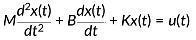
バネ・質量・ダンパー系では、二次微分方程式がシステムの動的動作を記述します。この方程式を初期条件がゼロのラプラス領域に変換すると、効果的に分析および操作できます。ラプラス領域への変換により、微分方程式が代数方程式に変換され、出力を分離するプロセスが簡略化されます。
バネ・質量・ダンパー系の標準微分方…
スプリング・マス・ダンパー・システムの 2 次微分方程式について考えてみます。システムは、初期条件がゼロでラプラス領域に変換されます。
次に、方程式を再配置して出力を分離し、特定の伝達関数を持つブロックに入る信号として解釈できます。
出力は、2 回積分するか、それに応じて後乗算することによって得られます。
簡単に言うと、右側の信号が接続され、システムの最終的なブロック線図表現につながります。
内部フィードバックループから項を因数分解することで、さらに単純化することができ、その結果、代替のブロック線図が得られます。
ブロック線図モデルには、加速度と速度を表す内部変数を組み込むこともできます。
1/sはラプラス領域での積分に対応するため、最初に加速度を積分して速度を求め、その後、速度を積分して変位信号を生成します。
システムの伝達関数は、入力信号とフィードバック信号のブロックをコンパレータの右側に移動し、内部フィードバックループを単純化することで求められます。結果として得られる方程式は、システムの伝達関数です。
View the full transcript and gain access to JoVE Core videos
Q1: How do you convert a second-order differential equation into a block diagram?
Transform the differential equation into the Laplace domain under zero initial conditions to convert it into an algebraic form. Rearrange to isolate the output, then interpret signals as entering blocks with specific transfer functions. Connect signals on the right-hand side and represent each operation as a block, creating a visual representation of the system's dynamic behavior.
Q2: What role does the 1/s operator play in block diagram representation?
In the Laplace domain, 1/s represents integration. Acceleration is first integrated using a 1/s block to obtain velocity, then velocity is integrated again to yield displacement. This cascading integration structure allows block diagrams to represent the relationships between acceleration, velocity, and displacement signals in dynamic systems.
Q3: How is a transfer function derived from a block diagram?
Move the block representing input and feedback signals to the right-hand side of the comparator. Simplify the internal feedback loop by factoring terms and algebraically manipulating the resulting equation. The final simplified equation yields the transfer function, which characterizes the system's input-output relationship and is essential for analyzing system behavior.
Q4: Why is block diagram simplification important for spring-mass-damper systems?
Simplification reduces complex representations into manageable forms by factoring internal feedback loops and combining blocks. This process clarifies the system's structure, making it easier to identify key relationships between variables like acceleration, velocity, and displacement. Simplified diagrams also facilitate transfer function derivation and control system design.
Q5: What internal variables are typically represented in a spring-mass-damper block diagram?
Block diagrams incorporate acceleration, velocity, and displacement as internal variables. These variables are interconnected through integration operations: acceleration integrates to velocity, and velocity integrates to displacement. Representing these variables explicitly shows the hierarchical signal flow and helps visualize how different system states relate to one another.
Q6: How does the Laplace transform simplify differential equation analysis?
The Laplace transform converts differential equations into algebraic equations under zero initial conditions, eliminating the need for calculus-based solutions. This transformation allows engineers to manipulate equations algebraically, isolate outputs more easily, and construct block diagrams that represent system dynamics. The resulting algebraic form is more suitable for block diagram representation and transfer function derivation.
Q7: How do block diagrams relate to the overall system transfer function?
Block diagrams visually represent the mathematical relationships described by differential equations and transfer functions. By manipulating the block diagram structure through simplification and rearrangement, engineers derive the overall transfer function. This function predicts system response to various inputs and enables design of control strategies for achieving desired performance in mechanical and electrical systems.