6.13
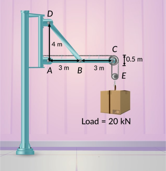
도르래에 외부 하중이 매달려 있는 지브 크레인을 생각해 보겠습니다. 크레인 부재의 치수가 그림에 나와 있습니다. 풀리에 마찰이 없다는 가정 하에 핀 조인트의 반력을 결정하려면 프레임 구조에 대한 체계적인 분석이 필요합니다.
시스템에는 두 가지 주요 구조 구성 요소가 있…
풀리에서 외부 하중이 가해지는 지브 크레인을 고려하십시오.
크레인 부재의 치수를 알고 있는 경우 풀리가 마찰이 없다는 점을 고려할 때 핀 조인트의 반력은 얼마입니까?
이 시스템은 2 포스 멤버 BD와 멀티 포스 멤버 ABC로 구성된 프레임 구조입니다.
자유물체 다이어그램을 고려하고 하부 풀리 섹션에 대한 힘 평형 조건을 적용하면 케이블의 장력을 얻을 수 있습니다.
C 지점을 고려할 때 수직 케이블의 장력은 아래쪽을 향하고 수평 케이블의 경우 조인트 A를 향합니다.
부재 DB에서 힘 FBD는 슬로프 삼각형을 사용하여 표현할 수 있습니다.
조인트 A의 모멘트 평형 조건은 BD를 따라 힘을 제공합니다.
힘 평형 조건을 적용하면 조인트 A에서 수평 및 수직 반력이 계산됩니다.
이제 부재 BD에 대한 자유물체 다이어그램을 고려할 때 힘 평형 조건을 조인트 D에 적용하여 D에서 수평 및 수직 반력을 얻을 수 있습니다.
Q1: What is the difference between a two-force member and a multi-force member in frame analysis?
A two-force member is a straight element subjected only to forces at its two ends, with forces equal in magnitude but opposite in direction, causing pure tension or compression. A multi-force member experiences more than two forces distributed along its length, including external loads, reaction forces at pin joints, and cable forces, resulting in complex stress distribution.
Q2: How do you determine cable tension in a jib crane pulley system?
For a frictionless pulley system, the load weight balances the tension in the cables. In the lower pulley section, each cable carries an upward tension equal to half the total load. For the upper pulley, the vertical cable tension remains the same as the lower section since it is part of the continuous cable system.
Q3: What equilibrium conditions are applied to find reaction forces at pin joints?
Force equilibrium conditions require that the sum of horizontal and vertical forces equals zero at each joint. Moment equilibrium conditions require that the sum of moments about a point equals zero. These conditions are applied systematically to free-body diagrams of each structural member to solve for unknown reaction forces.
Q4: How is the force in member BD resolved in a jib crane frame analysis?
The force FBD in member BD is resolved into horizontal and vertical components using a slope triangle, which relates the member's geometry to its force components. The moment equilibrium condition at joint A yields the magnitude of FBD. Substituting known dimensions and pulley radius values determines FBD as 50 kN in this example.
Q5: What are the typical reaction force values at pin joints in a loaded jib crane?
Reaction forces depend on load magnitude and structural geometry. In this jib crane example, the horizontal reaction force at joint A is 40 kN, while the vertical reaction force is -20 kN. At joint D, the horizontal reaction is -30 kN and the vertical reaction is 40 kN, determined by applying force equilibrium conditions.
Q6: Why is analyzing the lower pulley section important before analyzing the upper pulley?
The lower pulley section directly supports the external load, establishing the cable tension value. This tension value propagates through the continuous cable system to the upper pulley section. Determining lower pulley tension first provides known force values needed to solve for reaction forces at pin joints in the frame structure.
Q7: How does the free-body diagram method apply to frame problem solving?
Free-body diagrams isolate each structural member and show all forces acting on it, including external loads, cable tensions, and reaction forces at pin joints. Applying force and moment equilibrium conditions to these diagrams systematically yields unknown reaction forces. This method using method of joints problem solving principles allows solving complex frame structures step by step.