11.8
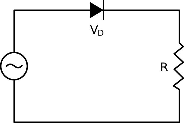
반파 정류기는 교류(AC) 전압을 단방향 전압으로 변환하도록 설계된 전자 장치의 기본 회로입니다. 이는 회로가 부하 저항 및 AC 전원과 직렬로 연결된 단일 다이오드로 구성되는 가장 간단한 형태의 다이오드 정류를 활용합니다.
반파 정류기의 작동은 다이오드가 한 방향으로…
다이오드 정류기 회로는 반파 또는 전파 구성을 사용하여 AC 전압을 단방향 DC 전압으로 변환합니다.
다이오드, 저항기 및 입력 정현파 신호로 구성된 반파 정류기 회로를 직렬로 조합하여 생각해 보십시오.
입력 신호의 양의 반주기 동안 전압이 다이오드의 전압 강하를 초과하거나 같을 때 순방향 바이어스가 되어 전류가 흐를 수 있습니다.
그런 다음 출력 전압은 입력 전압에서 다이오드의 전압 강하를 빼서 결정됩니다.
반대로, 음의 반주기 동안 입력 전압은 다이오드의 전압 강하보다 낮고 다이오드는 비전도성 상태로 유지되어 출력 전압이 0이 됩니다.
입력 전압이 평균값 0으로 극성을 변경함에도 불구하고 출력은 정류로 인해 일관된 평균값으로 단방향을 유지합니다.
피크 역전압은 다이오드가 손상 없이 견딜 수 있는 최대 역전압을 나타냅니다.
반파 정류기에서 이것은 입력 전압이 음의 방향으로 피크에 도달할 때 음의 반주기 동안 발생합니다.
따라서 피크 역 전압은 입력 전압 피크와 같지만 극성이 반전됩니다.
View the full transcript and gain access to JoVE Core videos
Q1: How does a half-wave rectifier convert AC voltage to DC?
A half-wave rectifier uses a single diode to convert alternating current into unidirectional voltage. During positive half-cycles, the diode becomes forward-biased when input voltage exceeds its threshold, allowing current flow and producing output voltage. During negative half-cycles, the diode remains reverse-biased and non-conductive, resulting in zero output. This creates a pulsating DC that flows only during positive input cycles.
Q2: What is the relationship between input and output voltage in a half-wave rectifier?
The output voltage in a half-wave rectifier equals the input voltage minus the diode's forward voltage drop during conduction. When the diode conducts during positive half-cycles, this voltage difference appears across the load resistor. During negative half-cycles, the output voltage drops to zero because the diode blocks current flow, resulting in no voltage across the load.
Q3: What is peak inverse voltage and why does it matter in rectifier circuits?
Peak inverse voltage (PIV) is the maximum reverse voltage a diode can withstand without breakdown. In a half-wave rectifier, PIV occurs during negative half-cycles when input voltage reaches its peak in the negative direction, equaling the input voltage peak with reversed polarity. Selecting a diode with adequate PIV rating prevents damage and ensures circuit longevity and reliability.
Q4: Why does the diode conduct during positive half-cycles but not negative ones?
During positive half-cycles, input voltage exceeds the diode's threshold voltage, creating forward-bias conditions that allow current flow. During negative half-cycles, input voltage falls below the diode's potential barrier, establishing reverse-bias conditions where the diode becomes non-conductive. This directional behavior is fundamental to how diodes rectify AC signals into unidirectional current.
Q5: What circuit components are required for a basic half-wave rectifier?
A basic half-wave rectifier requires three essential components: a diode, a load resistor, and an AC power source connected in series. The diode controls current direction, the resistor provides the load path, and the AC source supplies the alternating input signal. This simple configuration forms the foundation of rectification circuits used in power supply applications.
Q6: How does a half-wave rectifier produce a consistent average DC value from a zero-average AC signal?
Although the input AC signal has an average value of zero due to equal positive and negative cycles, the half-wave rectifier blocks negative half-cycles entirely. This asymmetry produces a pulsating DC output that flows only during positive input cycles, resulting in a consistent positive average value. The rectification process effectively removes the negative portion of the waveform.
Q7: How does a half-wave rectifier compare to a full-wave rectifier in terms of output?
A half-wave rectifier conducts during only positive half-cycles, producing output pulses at half the input frequency with lower average DC value. A full-wave rectifier utilizes both positive and negative half-cycles, delivering output pulses at twice the frequency with higher average DC value and smoother waveform. Full-wave configurations provide more efficient power conversion and reduced ripple.