This video demonstrates the optogenetic manipulation of neural circuits involved in the sleep-to-wakefulness transition in mice. The procedure involves surgically implanting an optic fiber and electrodes into the brain and muscles to enable light stimulation and electrophysiological recording. By delivering light to activate light-sensitive cation channels in the bed nucleus of the stria terminalis (BNST), neuronal activity is modulated, allowing researchers to analyze brain and muscle signals associated with wakefulness induction.
Een abonnement op JoVE is vereist om deze inhoud te bekijken. Log in of start vandaag met uw gratis proefperiode.
Methodenartikel
Optogenetic Manipulation of Neural Circuits for the Sleep-to-Wakefulness Transition in Mice
1.4K weergaven
⸱
29 augustus 2025
In dit artikel
Samenvatting
Protocol
All procedures involving animal models have been reviewed by the local institutional animal care committee and the JoVE veterinary review board.
1. Animal Surgery, Virus Injection, Electrode for EEG/EMG, and Optical Fiber Implantation
CAUTION: Appropriate protection and handling techniques should be selected based on the biosafety level of the virus to be used. Adeno-associated virus (AAV) should be used in an isolated P1A-graded room for injection, and the tube carrying AAV must be sterilized with an autoclave after all the volume is used up. The surgical site and all implanted material should be clean and sterile during use.
NOTE: See Figure 1.
1. Disinfect the surgical equipment with the autoclave.
2. Anesthetize mice with isoflurane using an anesthetic vaporizer. Observe until the mouse has reached the desired depth of anesthesia, determined by loss of response to pinching the tail with forceps. Apply ophthalmic ointment to the eyes to prevent them from drying.
3. Disinfect the surgical field with iodine solution or 70% ethanol (EtOH, 3x) and dry sufficiently. Allow the virus to thaw on ice as the surgery is being performed. Cover the surgical area with absorbent lab bench paper.
4. Fix the mouse's head in the stereotactic apparatus with ear bars and a nose pinch. After confirming the head is held stably, make a midsagittal incision in the scalp to ensure the positions of the bregma and lambda are located at the same level on a horizontal line.
5. To avoid a positioning gap, appropriately adjust the levels of the nose pinch and ear bars up and down. The bregma and lambda refer to the intersection between the sutura saggitalis and sutura coronalis or sutura lambdoidal, respectively (Figure 2).
6. Use Serafin clamps to hold the skin to maintain access to the cranium. After exposure of the skull, disinfect the surface of the skull with iodine or 5% H2O2, to enable the cranial sutures including the bregma and lambda to be visualized more clearly.
7. Prepare AAV vector injection:
1. Wash the inside of a 10 mL syringe (see Table of Materials) sequentially with 70% EtOH, 100% EtOH, and sterilized water, 5 times each. Secure the syringe in the clamp of a microinjection pump arm and make sure all the solution in the syringe is discharged.
2. Carefully aspirate 2 µL of mineral oil without air bubbles, then aspirate the designated volume of the virus solution. After aspiration, manipulate the plunger button and confirm that the virus solution emerges at the tip of the needle.
NOTE: The injection volume of the virus solution was determined in pilot experiments using the same mouse strain and the same virus product. The relation between the volume of the virus solution and the extent of the infection area should be estimated in advance.
8. Inject AAV vector:
1. Adjust the tip of the microinjection needle on the bregma and note the coordinates as the original point. Move the tip to the designated injection site (for the BNST: anteroposterior + 0.2 mm, mediolateral ± 1.0 mm, dorsoventral - 4.2 mm) and place the tip of the needle in the position. Put a mark on the skull and drill holes of approximately 2 mm in diameter using a dental drill with a 0.7 mm carbide cutter. Be careful not to damage the dura or brain tissue.
2. After removing blood from around the holes with a cotton swab, slowly move the needle into the position of the BNST. Slowly inject the designated amount of virus solution (0.07 µl/min) with a mechanical microinjector. After completing the injection, leave the needle for 5 minutes to allow the solution to sufficiently infiltrate the BNST tissue. Carefully remove the needle.
3. For bilateral injections, repeat steps 1.8.1-1.8.2 on the other side. Throughout the procedure, apply sterile saline to keep the skull moist.
NOTE: We used custom electroencephalography (EEG)/electromyography (EMG) implants (Width: 5 mm, depth: 7 mm, height: 1 mm) with four EEG electrodes (4 mm), two EMG electrodes (2 mm; cut the 4 mm electrode to 2 mm with nippers) and 6 electrodes (4.5 mm) (Figure 2A).
9. Solder two stainless steel wires (see Table of Materials) from which 1 mm of the insulation is stripped off both ends to the EMG electrodes. Adjust the center of the electrodes to the bregma, mark the position of each EEG electrode (anteroposterior ± 1.5 mm, mediolateral ± 1.0 mm), and determine the position of the implant (Figure 2B).
10. Implant optical fibers:
1. Attach an optic fiber ferrule to the manipulator and rotate the manipulator arm so that it has an angle of ±30° against a horizontal line (this process is only needed to avoid interference between electrodes and optic fibers, such as in the case of BNST stimulation). Put the fiber tip on the bregma and record the coordinates.
2. Move the tip to the targeted insertion line and mark the position on the skull. Also, put additional marks near the insertion site for the anchor screws. Drill the skull on each site with a dental drill to insert the optic fiber and fix the screw. Fix the screw on the skull. Be careful not to break the dura or damage any tissue with the screw.
3. Insert the optic fiber gently until reaching above the BNST with a manipulator. The ferrule should rest on the remaining cranium (Figure 1B).
4. Apply photocurable dental cement (see Table of Materials) to cover the fiber and the screw. The reaction time to solidify the glue should be specified by the manufacturer's manual (Our material needs exposure to light for at least 10 seconds with specific wavelength photo-generators. It is unnecessary to dry the glue after this).
5. In this step, make sure that no materials (screws or glue) occupy the mounting space for the electrodes. In addition, avoid making any interruption in the cement for the ferrule connecting to the optic fiber and cable. Repeat steps 1.10.1-1.10.4 on the opposite side for bilateral stimulation.
11. Drill holes for EEG/EMG electrodes. Insert the tips of the electrodes into the holes. Hold the implant and apply cyanoacrylate adhesive to the space between the skull and the electrodes. Insert again with attention not to interfere with any materials.
12. Cover the circumference of the electrodes and optic fibers with cyanoacrylate adhesive, followed by the application of cyanoacrylate accelerant on the adhesive. This step avoids causing any interruption at the ferrule-to-optic cable and electrode-to-lead wire connecting zone (Figure 1C).
NOTE: Cyanoacrylate adhesive and its accelerant are harmful to the mouse eye. Pay attention not to cause spillage of these chemical substances. Also, be careful not to strongly touch the electrodes and the fibers in order to avoid unexpected deviation immediately after adhesive solidification.
13. Expose the mouse neck muscles and insert the wires for the EMG electrode under the muscle. Adjust the length of the EMG electrode so that it is located just under the nuchal muscles. A light connection between the tip of the electrode and the muscle fascia is enough to catch the EMG signal.
14. Apply cyanoacrylate adhesive to fill the implants and solidify the adhesive with acceleration liquid. Then, put the mouse on a heating pad for recovery until the postural reflex appears. Adjust heating pad temperature to animal resting body temperature (36.0 °C in ZT 0-12 in case of C57BL6 mice; do not exceed 38.0 °C).
NOTE: An antibiotic is not required for sterile surgery. Follow your local institutional guidelines for post-operative analgesia. Keep the mice in a home cage for a recovery period of at least 7 days.
2. EEG/EMG Monitoring with Photo-excitation of Targeted Neurons in Specific Sleep States
CAUTION: This protocol includes use of class 3B laser equipment or LED devices. Experimenters should be aware of safety information. Protective eye goggles are required.
1. Before connecting the laser cable to the optic fiber, adjust the laser intensity with a scaler. Tether the tip of the laser cable to an unused optic fiber with a ferrule and confirm that there is no space at the junction between the fiber and the cable.
2. Turn on the main switch of the laser and wait 20 minutes for it to warm up.
3. Emit the laser to the intensity checker and adjust the laser intensity to 10 mW/mm2. Change the laser mode to transistor logic and confirm that light pulses are emitted from the fiber controlled by the pattern regulator, which is set at 10 ms for duration, 40 ms for rest, 20 times for cycle, and 20 times repeat (that is, 20 Hz of 10 ms light pulses for 20 s).
4. After the recovery period, move the mice to the experimental chamber for recording EEG/EMG. House mice were kept at a constant 23 °C with a 12 h light/dark cycle with food and water available ad libitum.
5. Connect the implanted electrode and cable adaptor which is tethered to a slip ring to avoid entanglement. It is recommended to cover the junction with light-impermeable material such as aluminum foil to prevent laser leakage. If a bilateral experiment is required, use a slip ring with a bifurcate attachment for the cables.
6. In this protocol, we assess latency to wakefulness from non-rapid eye movement (NREM) sleep or rapid eye movement (REM) sleep, so the recording time should be limited in optimized zeitgeber time (ZT0 is defined as the time when the light is on). This protocol was conducted between ZT4 - ZT10. Let the mice stay freely in the experimental chamber for at least 1 h as acclimatization.
7. During the experimental period, monitor EEG and EMG signals in the same monitor and evaluate the mouse's state as wakefulness, NREM sleep, or REM sleep. Use the gain control for each wave to make it easier to distinguish each state.
8. For measurement of NREM sleep to wakefulness latency, observe stable NREM sleep for 40 s or stable REM sleep for 30 s, then turn on the switch of the pattern generator for photostimulation (this protocol generates 20 Hz of 10 ms light pulses for 20 s). Confirm laser emission to the implanted optic fibers.
9. Record EEG/EMG signals until the sleeping state changes to wakefulness. If two or more experimental trials are needed, limit optogenetic manipulation to once a day because photostimulation is an artificial intervention that might affect sleep/wakefulness architecture.
10. After the experiment, deeply anesthetize and perfuse with sterile saline and paraformaldehyde (PFA) for sampling the whole brain for immunohistochemical analysis.
Toegang beperkt. Log in of start een proefperiode om deze inhoud te bekijken.
Resultaten
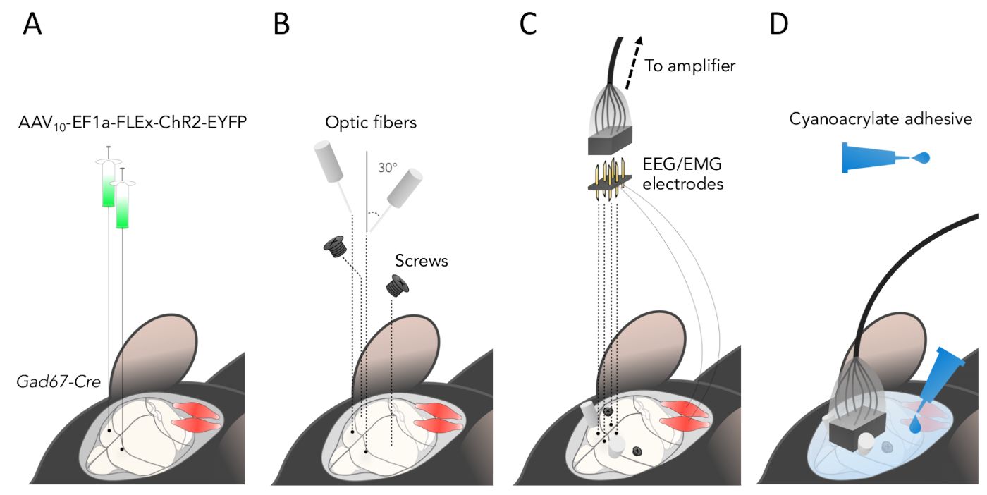
Figure 1: Procedure to inject AAV, implant optic fibers, and EEG/EMG impl...
Toegang beperkt. Log in of start een proefperiode om deze inhoud te bekijken.
Materialen
| Naam | Bedrijf | Catalogusnummer | Opmerkingen |
|---|---|---|---|
| 1x1 Fiber-optic Rotary Joints | Doric | FRJ 1x1 FC-FC | for optogenetics |
| 6-pin header | KEL corporation | DSP02-006-431G | |
| 6-pin socket | Hirose | 21602X3GSE | |
| A/D converter | Nippon koden | N/A | Analog to digital converter |
| AAV_{10} -EF1a-DIO-ChR2-EYFP | 3.70×10^{13} (genomic copies/ml) | ||
| AAV_{10} -EF1a-DIO-EYFP | 5.82×10^{13} (genomic copies/ml) | ||
| Ampicillin | Fuji film | 014-23302 | |
| Amplifier | Nippon koden | N/A | for EEG/EMG recording |
| Anesthetic vaporizer | Muromachi | MK-AT-210D | |
| Automatic injecter | KD scientific | 780311 | |
| Carbide cutter | Minitor | B1055 | φ0.7 mm. Reffered as dental drill, used with high speed rotary micromotor |
| Cyanoacrylate adhesion (Aron alpha A) and acceleration | Konishi | #30533 | |
| Dental curing light | 3M | Elipar S10 | |
| Epoxy adhesive | Konishi | #04888 | insulation around the solder of 6-pin and shielded cable |
| Fiber optic patch cord (branching) | Doric | BFP(#)_50/125/900-0.22 | |
| GAD67-Cre mice | provided by Dr. Kenji Sakimura | Cre recombinase gene is knocked-in in the Gad67 allele | |
| Hamilton syringe | Hamilton | 65461-01 | |
| High speed rotary micromotor kit | FOREDOM | K.1070 | Used with carbide cutter |
| Interconnecting sleeve | Thorlab | ADAF1 | φ2.5 mm Ceramic |
| Isoflurane | Pfizer | 871119 | |
| Laser | Rapp OptoElectronic | N/A | 473nm wave length |
| Laser intesity checker | COHERENT | 1098293 | |
| Laser stimulator | Bio research center | STO2 | reffered as pulse generator in text |
| Optic fiber with ferrule | Thorlab | FP200URT-CANNULA-SP-JP | |
| pAAV2-rh10 | provided by PennVector Core | ||
| pAAV-EF1a-DIO-EYFP-WPRE-HGHpA | Addgene | plasimid # 20296 | |
| pAAV-EF1a-DIO-hChR2(H134R)-EYFP-WPRE-HGHpA | provided by Dr. Karl Deisseroth | ||
| Patch cord | Doric | D202-9089-0.4 | 0.4m length, laser conductor between laser and rotary joint |
| pHelper | Stratagene | ||
| Photocurable dental cement | 3M | 56846 | |
| Serafin clamp | Stoelting | 52120-43P | |
| Shielded cable | mogami | W2780 | Soldering to 6-pin socket for EEG/ EMG recording |
| Sleep recording chamber | N/A | N/A | Custum-made (21cm× 29cm × 19cm) with water tank holder |
| Sleep sign software | KISSEI COMTEC | N/A | for EEG/EMG analysis |
| Slip ring | neuroscience,inc | N/A | for EEG/EMG analysis |
| Stainless screw | Yamazaki | N/A | φ1.0 x 2.0 |
| Stainless wire | Cooner wire | AS633 | 0.0130 inch diameter |
| Stereotaxic frame with digital console | Koph | N/A | Model 940 |
| Syringe needle | Hamilton | 7803-05 | |
| Vital recorder software | KISSEI COMTEC | N/A | for EEG/EMG recording |
