This video demonstrates the setup and mechanism of transcranial direct current stimulation (tDCS) for modulating human motor function. By placing the anode over the primary motor cortex and the cathode over the contralateral supraorbital area, the targeted electrical stimulation increases cortical excitability, enhancing motor neuron activity and improving motor performance.
Een abonnement op JoVE is vereist om deze inhoud te bekijken. Log in of start vandaag met uw gratis proefperiode.
Methodenartikel
Non-Invasive Electrical Brain Stimulation for Modulating Human Motor Neuron Activity
577 weergaven
⸱
29 augustus 2025
In dit artikel
Samenvatting
Protocol
All procedures involving human participants have been performed in compliance with the institutional, national, and international guidelines for human welfare and have been reviewed by the local institutional review board.
1. Safety Screening
- Screen the participant for potential contraindications for noninvasive brain stimulation, e.g., by using questionnaires.
2. Motor Cortex Localization
- Locate the participant's hand motor cortex by one of two distinct approaches: by locating the brain representation of the muscle of interest by transcranial magnetic stimulation (TMS)-induced motor evoked potential (MEP), or by locating the standard primary motor cortex (M1) position (C3/C4) based on the electroencephalogram (EEG) 10/20 international system with a measuring tape.
- For TMS-induced MEP recording ask the participant to remove any object that may be influenced by TMS magnetic field, including credit cards, mobile phones and metal objects in general.
- Ask the participant to sit comfortably.
- Verify connections between the electromyography (EMG) amplifier and the computer used for signal configuration and acquisition when using a software interface.
- Turn on the EMG amplifier and connect the EMG electrode cables.
- Clean the participant's skin by softly rubbing with skin preparation paste in the regions of the hand where the electrodes will be placed. Remove excess with a clean gauze pad.
- Attach EMG surface electrodes in a belly-tendon montage on the hand muscle of interest (e.g., M. abductor pollicis brevis of the right hand) and connect a ground electrode (e.g., on the forearm). The purpose of the study is to determine which hand muscle to use.
NOTE: For reusable electrodes it is necessary to apply a small amount of conductive paste on the electrode surface before attaching it to the participant's skin. - (optional step) Start the recording software for MEP acquisition if MEP data storage is desired.
- Check the EMG impedance values. Ensure that the impedance is < 20 kOhm.
- Turn on the magnetic stimulator and charge the capacitor by pressing the corresponding "charge" button.
- Place a figure-of-eight TMS coil on the participant's scalp on the interhemispheric fissure and move it to the motor cortex area (around positions C3/C4 of the EEG 10/20 international system). Hold the TMS coil at a 45 °-50 ° angle referenced to the interhemispheric fissure, with the handle oriented backward, producing a cortical current flow from posterior to anterior.
NOTE: Two distinct TMS coils are used for motor cortex localization: figure-of-eight or circular coils. If possible, use a figure-of-eight coil as it provides more focal brain stimulation and greater reliability of measurements of cortical excitability. - When the magnetic stimulator is charged (visible on the display), discharge the stimulator either by pressing the trigger button or by stepping on the foot switch or automatically by a software program. This will subsequently deliver a single TMS pulse through the connected TMS coil placed over the participant's scalp. Default TMS pulse settings (e.g., 100 µs rise time of the induced current and 800 µs decay time for monophasic stimuli; shorter decay times for biphasic stimuli) are specific to the device (firmware).
- Start with low stimulation intensity (e.g., set the intensity to 45% output using the stimulation intensity controller knob on the stimulator) and watch for MEPs visible on the EMG amplifier.
- If no MEP is visible, increase the stimulation intensity in 2-5% steps until an MEP is clearly present (e.g., 0.5-1 mV amplitude). Repeat stimulation by pressing the trigger button or activating the foot switch if pulse delivery is not automated. Inform the participant that stimulation will be slightly stronger and that limb movements, facial twitching, and eye blinks are expected.
NOTE: Establish a minimum interval of 5 seconds between pulses to avoid low-frequency stimulation effects on brain excitability.
- If no MEP is visible, increase the stimulation intensity in 2-5% steps until an MEP is clearly present (e.g., 0.5-1 mV amplitude). Repeat stimulation by pressing the trigger button or activating the foot switch if pulse delivery is not automated. Inform the participant that stimulation will be slightly stronger and that limb movements, facial twitching, and eye blinks are expected.
- Move the coil radially in 1 cm steps around the initially stimulated site to find the spot with the largest MEP response following the application of single TMS pulses. From there, start again moving the coil to secure the "hotspot" (cortical area with maximal MEP amplitude).
NOTE: The use of a head cap (e.g., used for grid markings) for the localization procedure is not recommended since the cap needs to be removed for non-invasive electrical brain stimulation (NEBS) electrode placement, and the hotspot position may be lost. - Reduce the stimulation intensity in approximately 2%-steps using the stimulation intensity controller knob on the stimulator (MEP must still be present). This will avoid inaccuracy due to supramaximal stimulation. Reconfirm the hotspot by moving the coil radially in 1 cm steps around the hotspot and checking for MEP size. The hotspot should still correspond to the largest and most consistent MEP amplitude.
NOTE: Ask the participant to voluntarily contract the muscle of interest if the hotspot is difficult to find (e.g., no MEP present at high stimulation intensities). By doing so, the stimulation intensity needed to elicit MEP is decreased and it may be easier to identify relevant cortical stimulation sites. If this method is used, ask the participant to relax the muscle after finding a relevant stimulation site and adjust stimulation intensity so that reliable MEPs can be found when the muscle is at rest. Proceed to find the hotspot. - Mark the hotspot position and coil orientation with a non-permanent skin marker.
- For bilateral M1 stimulation, repeat steps 2.11 to 2.16 for the contralateral limb.
3. NEBS Electrode Preparation
- Connect cables to rubber electrodes and place the electrodes inside the sponge bags. Make sure the electrode size and sponge bag size match. Materials are commercially available in standard sizes (e.g., 5x5 cm2, 5x7 cm2).
- Soak sponge bags on both sides with isotonic sodium chloride (NaCl) solution, but avoid excessive soaking to prevent salt bridges or dripping onto the volunteer.
- This step is optional: To prevent leakage of NaCl solution when using bandages instead of rubber bands, place the electrodes and sponge bags inside non-conductive rubber sponge covers.
NOTE: Alternatively, cover the rubber electrode with conductive paste and place it directly on the participant's head, i.e., not using sponge bags or rubber sponge covers.
- This step is optional: To prevent leakage of NaCl solution when using bandages instead of rubber bands, place the electrodes and sponge bags inside non-conductive rubber sponge covers.
4. NEBS Electrode Placement (Figure 1)
- Find the head marking(s) indicating the motor cortical hotspot and separate the hair around the area.
- To improve conductance clean the skin before electrode placement by gently rubbing the skin area around the head markings with a swab soaked with 40-50% alcohol or skin preparation paste. Do not scratch the skin! Remove excess with a swab and clean area again with isotonic NaCl solution. Dry the area afterward.
NOTE: Make sure the head marking(s) remain visible; remark if needed. - Place one electrode following the head marking for the M1 of interest (contralateral to the hand of interest). Bring the sponge as much as possible into direct contact with the skin. Place the electrode cable towards the participant's back to avoid disturbance during stimulation and/or task execution and to ease connection to the NEBS device.
NOTE: The hair below the electrode should get damp. In case of excessive hair moistening, use paper or hand towels to absorb the excess.
NOTE: For anodal tDCS, the electrode placed on the motor cortical hotspot of interest (increase of excitability is desired) corresponds to the anode, usually connected to the red cable. The cathode (usually connected to a black or blue cable) is placed on the opposite supraorbital area or M1 (see below). Conventionally, electrode placement is the same for transcranial random noise stimulation (tRNS), although in the classical protocol, there is no polarity specificity due to the alternating current flow. Specific placement may be important if the stimulation settings include a stimulation offset. - For unilateral M1 stimulation, place the second electrode (for anodal tDCS: the cathode) over the contralateral supra-orbital area (corresponding to electrode Fp2 in the EEG 10/20 international system). Make sure the cable is oriented towards the back of the participant.
- Cover the head twice with an elastic bandage circularly in the medio-lateral direction to stabilize the M1 electrode, then use the remaining bandage to cover the head circularly in the anterior-posterior direction to stabilize both electrodes.
- Use an adhesive tape to fix the end of the bandage.
- Secure the cables with adhesive tape on the participant's neck or shirt.
- Connect electrode cables to the NEBS device.
5. Stimulation
- Switch on the NEBS device.
- Adjust NEBS device settings regarding stimulation type (tDCS or tRNS), intensity (e.g., 1 mA, 1.5 mA, or 2 mA), duration (e.g., 10-40 min), ramping up and down (time between the beginning of stimulation and maximum intensity, typically 8-15 sec), and additional factors related to stimulation type (e.g., frequency spectrum for tRNS).
NOTE: Conventionally, sham stimulation includes ramping up immediately, followed by ramping down. Accordingly, the participant feels the stimulation, but the duration of the stimulation is not sufficient to exert lasting effects on brain function. Some NEBS devices include a study mode that allows the blinding of the participant and investigator by entering a study-specific subject code. The code determines stimulation settings automatically. Alternatively, a second experimenter may set the stimulation settings in each session and cover the display from the experimenter conducting the stimulation. - Inform the participant about potential side effects associated with NEBS. Common adverse effects include skin itching/tingling or burning sensation underneath the electrodes, headache, and discomfort. The burning sensation may be a sign of poor electrode contact with the skin.
- Start the stimulation.
NOTE: Common stimulation duration lasts approximately 10-20 min based on reports investigating changes in cortical excitability (see representative results section). Empirically, the maximum stimulation duration was set to 40 min. - Check for continuity of stimulation during ramping up and stimulation. If the impedance is too high or the electrodes are in bad contact with the skin, the stimulation may terminate automatically.
NOTE: In case the impedance is too high or the participant reports increasing discomfort during the stimulation, try to decrease impedance by, e.g., better fixating the electrodes at the stimulation sites or adding a conductive medium. NaCl solution may be added by using a syringe directly in the sponges after their placement on the head.
NOTE: Some devices report the impedance throughout the stimulation for safety reasons. The NEBS device may shut off if the impedance reaches a specific threshold (e.g., 55 kOhms).
Toegang beperkt. Log in of start een proefperiode om deze inhoud te bekijken.
Resultaten
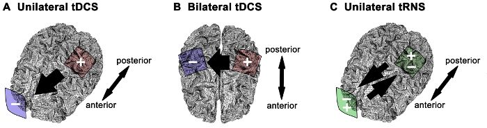
Figure 1. Electrode montages and current direction for distinct NEBS strategies. (A) For uni...
Toegang beperkt. Log in of start een proefperiode om deze inhoud te bekijken.
Materialen
| Naam | Bedrijf | Catalogusnummer | Opmerkingen |
|---|---|---|---|
| NEBS device (DC Stimulator plus) | Neuroconn | ||
| Electrode cables | Neuroconn | ||
| Conductive-rubber electrodes | Neuroconn | 5x5 cm | |
| Perforated sponge bags | Neuroconn | 5x5 cm | |
| Non-conductive rubber sponge cover | Amrex-Zetron | FG-02-A103 | Rubber pad 3"*3" |
| NaCl isotonic solution | B. Braun Melsungen AG | A1151 | Ecoflac, 0,9% |
| Cotton crepe bandage | Paul Hartmann AG | 931004 | 8x5m, textile elasticity |
| Adhesive tape (Leukofix) | BSN medical | 02122-00 | 2,5cm*5m |
| Skin preparation paste | Weaver | 10-30 | |
| Magnetic stimulator | Magstim | 3010-00 | Magstim 200 |
| EMG conductive paste | GE Medical Systems | 217083 | |
| EMG bipolar electrodes | e.g., Natus Medical Inc. Viking 4 | ||
| EMG amplifier | e.g., Natus Medical Inc. Viking 4 | ||
| Cable for EMG signal transmission | e.g., Natus Medical Inc. Viking 4 | ||
| Data acquisition unit | Cambridge Electronic Design (CED) | MK1401-3 | AD converter |
| Computer for signal recording and offline analysis | |||
| Signal 4.0.9 | Cambridge Electronic Design (CED) | Software | |
| Non-permanent skin marker | Edding | 8020 | 1 mm, blue |
Meer artikelen verkennen
Transcraniale Gelijkstroomstimulatiestimulatie van de motorische cortextechniek voor elektrodeplaatsingisotone natriumchlorideoplossingniet-invasieve hersenstimulatiemodulatie van de activiteit van motorneuronenverhoging van de corticale exciteerbaarheidsupraorbitale elektrodeplaatsingvoltooiing van het elektrische circuit
