This video demonstrates the use of a microfluidic device to quantify bacterial motility through a porous matrix composed of randomly arranged pillars. Fluorescently labeled bacteria are introduced into the device, imaged via microscopy as they move through the porous matrix into the observation channel, and analyzed to generate a breakthrough curve (BTC).
Een abonnement op JoVE is vereist om deze inhoud te bekijken. Log in of start vandaag met uw gratis proefperiode.
Methodenartikel
Assessing Bacterial Motility Using a Microfluidic Device
531 weergaven
⸱
28 november 2025
In dit artikel
Samenvatting
Protocol
1. Bacterial culture conditions
- Working under a laminar flow hood, use 100 μL of a glycerol stock of green fluorescent protein (GFP)-tagged Pseudomonas putida KT2440 (1 × 10⁷ mL-1, stored at -80 °C) to inoculate 5 mL of Luria-Bertani (LB) medium. Incubate at 30 °C while shaking at 250 rpm overnight.
- The next day, resuspend 100 μL of the overnight culture in 5 mL LB medium and incubate under the same conditions for 5h (exponential phase). Sample a 1 mL aliquot into a 2 mL tube, allow to cool to room temperature (~15 min), and centrifuge (2300 x g for 5 min).
- Remove the supernatant and add 1 mL motility buffer to the pellet. Vortex briefly to homogenize the sample. Dilute to reach the desired cell concentration, e.g., 5 x 10⁵ mL-1.
- For experiments involving natural communities, such as those derived from streams, prepare a non-selective cultivation medium. For instance, use sterile-filtered and autoclaved stream water or an artificial stream water medium amended with a complex carbon source (LB medium).
2. Preparation of a microfluidic device in polydimethylsiloxane (PDMS)
- Design the desired porous geometry by means of computer-aided drafting (CAD) software, which consists of a matrix of circles (that is, the impermeable obstacle to flow), described by radius size and center coordinates.
NOTE: An example of a porous geometry with randomized grain and pore sizes is provided in Figure 1A. An observation channel without obstacles close to the outlet facilitates the acquisition of breakthrough curves (BTCs). - Based on the chosen geometry, prepare a mold using standard SU-8 photolithography.
NOTE: Alternatively, molds can also be ordered from a dedicated microfabrication facility. In order to obtain heterogeneous fluid flow in the horizontal plane, it is important to design the thickness of the microfluidics chamber of the same order of magnitude as the average pore throat size. However, make sure that the dimensions of the microfluidic device are suitable for observation under the microscope (e.g., work on microscope slides). - Prepare 50 g of PDMS by adding 10% of cross-linker (dimethyl, methylhydrogen siloxane copolymer) to 90% of elastomer by weight, using a syringe without a needle. Work under clean conditions and avoid dust as much as possible. Mix the two reagents in a clean, disposable container and apply vacuum (100 mbar) for 30 min to remove dissolved air and bubbles from the viscous PDMS.
- Place the mold into a Petri dish (100 mm in diameter, 15 mm high). Pour the PDMS onto the mold to the desired height (e.g., 2-5 mm). Cover the petri dish and keep it at 60 °C for 4 h (overnight for thicker layers) to cure.
NOTE: For visualization purposes, light should be able to pass through the PDMS; thus, a thin layer between 2 mm to 5 mm is desirable. Thicker layers (>5 mm) reduce the device transparency, and thinner ones are subjected to deformations during application. - Remove the mold from the oven and allow the microfluidic device to cool to room temperature. Once it is cooled, carefully remove the desired portion of PDMS with a scalpel.
NOTE: Strong pressures on the mold result in mold fractures. Do not touch the PDMS with your bare hands, as fingerprints will affect optical transparency. - Temporarily seal the bottom of the PDMS channel (where the desired geometry has been engraved) with tape. With a 0.5 mm diameter biopsy puncher, pierce the microfluidic channel to create an inlet and an outlet fitting the 0.5 mm (inner diameter) tubing.
NOTE: The soft nature of PDMS will ensure tightness once the tubing will be inserted. Inlet and outlet channels cannot be made after the PDMS has been sealed to the glass. - Seal the microfluidic channel via oxygen plasma bonding using the high-frequency generator (plasma bonder, Table of Materials). For this, clean a silicate glass slide (25 mm x 75 mm) with ethanol and let it dry. Remove the tape from the PDMS channel and place the channel with the porous side facing up. Treat the silicate glass slide and PDMS surfaces with plasma for about 45 s at room temperature.
- Place the PDMS channel onto the silicate glass slide and heat at 100 °C for 30 min on a hot plate.
- Remove the microfluidic device from the hot plate and cool it to room temperature. Connect the PDMS channel inlet with tubing. Apply a vacuum for 30 min to remove air from PDMS, which is almost impermeable to fluids but permeable to gas.
- Prepare 100 mL of motility buffer (10 mM potassium phosphate, 0.1 mM ethylenediaminetetraacetic acid (EDTA), supplemented with 1% w/v glucose, pH 7.0) and inject 1 mL of it into the microfluidic device using a syringe pump operated at 10 µL min-1.
NOTE: As the PDMS is undersaturated in gas (due to the previous vacuum step), bubbles will disappear within ~30 min.
3. Analyze bacterial transport using PDMS microfluidic devices
- Place the PDMS microfluidic device previously saturated with the motility buffer on the microscope stage. Use tape to fix the tubing to minimize disturbance of the flow during stage movement.
- Move the microscope stage to the observation channel close to the outlet. Using bright field microscopy or phase contrast, focus on the center of the observation channel and adjust the magnification to visualize individual bacterial cells.
- Switch the light path settings to fluorescence microscopy and adjust the camera exposure time to resolve individual bacterial cells (e.g., 100 ms), or such that fluorescence signals of cells are at least 3x stronger than background noise.
- Next, insert the inlet tubing into a 2 mL tube containing the bacterial suspension. Reverse pump direction and start withdrawing the suspension at a flow rate of 1 µL min-1.
- Scan the cross-section of the entire observation channel, recording a composite picture every 2 min, over the entire duration of the experiment.
Toegang beperkt. Log in of start een proefperiode om deze inhoud te bekijken.
Resultaten
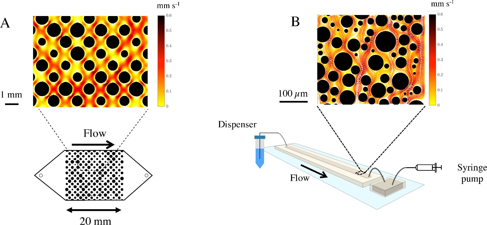
Figure 1: Fluidic devices to study microbial transport in porous media (A) Illustration of a f...
Toegang beperkt. Log in of start een proefperiode om deze inhoud te bekijken.
Materialen
| Naam | Bedrijf | Catalogusnummer | Opmerkingen |
|---|---|---|---|
| Ethylenediaminetetraacetic acid (EDTA) | Sigma | ||
| Elastomer Sylgard 184 | Dowsil | 101697 | |
| Flow cytometer NovoCyte | Acea | ||
| Glucose | Sigma | https://www.makeblock.com/project/xy-plotter-robot-kit | |
| Luria-Bertani (LB) broth | BD | ||
| Liquid dispenser, XY Plotter Robot Kit | makeblock | ||
| Microscope Axio Imager | Zeiss | ||
| Microscope AxioZoom v16 | Zeiss | ||
| Microscope slides, 75 mm × 25 mm | Corning | ||
| Minipuls 3 peristaltic pump | Gilson | ||
| Plasma bonder Corona SB | BlackHole Lab | ||
| Potassium phosphate | Sigma | ||
| Syringe pump New Era NE 4000 | New Era | ||
| Syto 13 Green Fluorescent Nucleic Acid Stain | Molecular Probes, Invitrogen | ||
| Tygon tubing | Ismatec | ||
| WF31SA universal milling machine | Mikron |
