1. Silicon wafer preparation
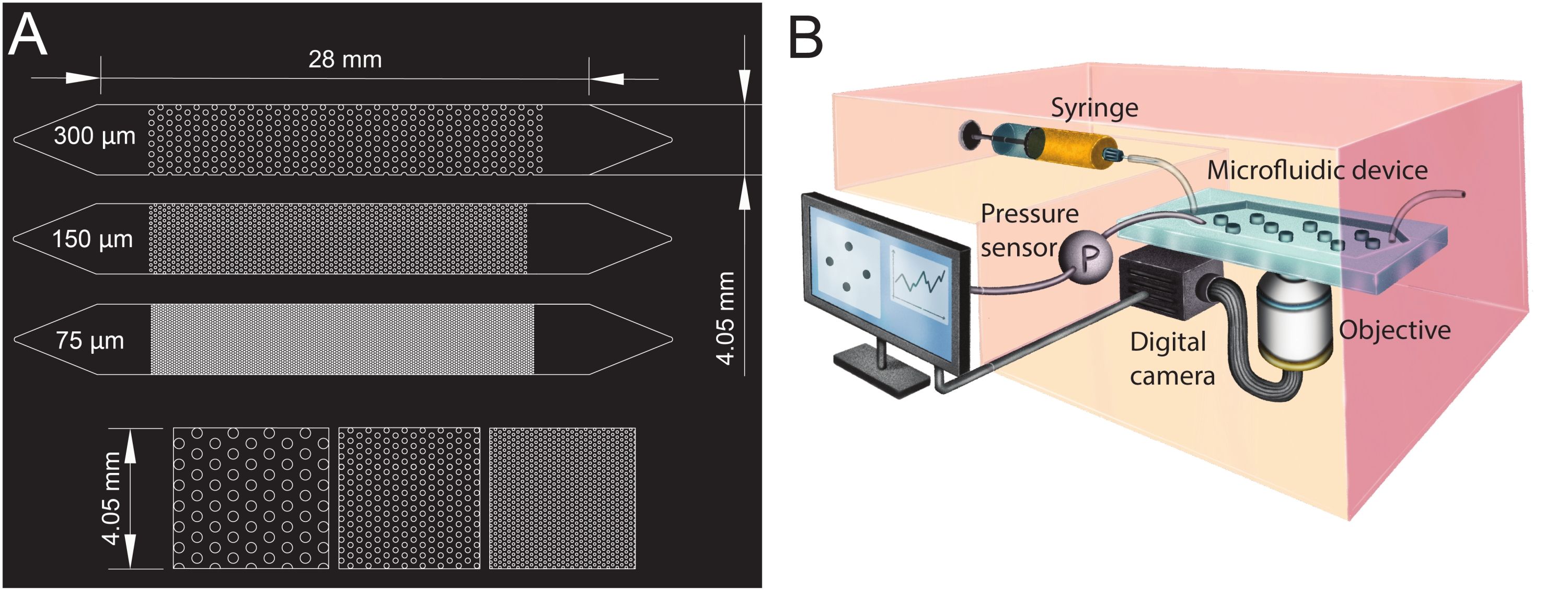
- Design the geometries of the microfluidic channel in computer-aided design (CAD; see Table of Materials) software and print it onto a transparent film to create the photomask (Figure 1A).
- Fabricate the master mold by soft lithography (under clean-room conditions) following the steps below.
- Bake the silicon wafer at 200 °C for 2 h.
- Place the wafer at the center of a spin-coater and pour SU8 3050 photoresist (see Table of Materials) onto the wafer. Spin coat at 1,700 rpm for 40 s with a 10 s/100 rpm ramp time.
NOTE: The spin-coating parameters were set to obtain a target thickness of 100 µm for the SU8 3050. - After the spin-coating process, soft bake the silicon wafer at 65 °C for 600 s and 95 °C for 2,700 s. Let the wafer cool at room temperature overnight.
NOTE: The overnight cooling enhances the adhesion of the SU8 to the wafer. - Place the photomask (step 1.1) onto the wafer and expose it to UV light, with an exposure energy of 250 mJ/cm² and at a wavelength of 350 nm.
- Post-exposure, bake the exposed substrate at 65 °C for 60 s and 95 °C for 300 s.
- Develop the silicon wafer to obtain the master mold by immersing it in a beaker filled with mrDev600 developer (see Table of Materials). Gently shake the beaker for 1,800 s to wash out the unpolymerized resist. Then, splash wash by spraying isopropanol on the silicon wafer and air dry.
- Hard bake the silicon wafer at 200 °C for 1,800 s.
- Silanize the master mold through vapor deposition of 20 µL of Trichloro (1H, 1H, 2H, 2H-perfluorooctyl) silane (see Table of Materials) placed on a glass slide next to the mold for 40 min in a vacuum desiccator, creating a gauge pressure of 100 mbar.
2. Fabrication of the microfluidic device
NOTE: The fabrication procedure described here is for a microfluidic device with one microfluidic channel. However, the same method can be applied to fabricate a microfluidic device with multiple microfluidic channels in parallel.
- Mix the elastomer with its crosslinker at a ratio of 10:1 (see Table of Materials) to prepare a polydimethylsiloxane (PDMS) mixture. Stir the mixture until it gets uniformly mixed and turns opaque due to the enclosed air bubbles.
- Degas the mixture in a vacuum desiccator, creating a gauge pressure of 100 mbar until the entrapped air bubbles are removed and it looks transparent. The time required for degassing is typically 30 min.
- Place the master mold (step 1) in a cell culture dish (see Table of Materials). Pour 20 g of the PDMS mixture on the master mold to produce channels with a final thickness of 5 mm.
- Bake the master mold at 70 °C for 2 h.
- Cut the cured PDMS around the microfluidic channel (at a distance of approximately 3 mm) using a blade, and then peel the PDMS microfluidic channel off the master mold.
- To create the microfluidic channels' inlet and outlet, punch holes with a biopsy punch (diameter of 1.5 mm) at its extremities (top of the triangles, see Figure 1A). Punch one additional hole at the center of the inlet triangle to install the pressure sensor later.
- Wash a glass slide and the microfluidic channel with a commercially available 1% detergent solution (see Table of Materials) for 5 min, then rinse them with deionized water. Thereafter, wash the PDMS microfluidic channel and the glass slide with isopropanol. Then, rinse them again with deionized water. Dry the PDMS microfluidic channel and the glass slide with compressed air at 1 bar for 1 min.
NOTE: The porous structure of the PDMS must be completely dry for the bonding to be effective. - Place the glass slide and the microfluidic channel in a plasma cleaner (see Table of Materials) and ensure that the surfaces to be bonded are facing up. Turn on the plasma cleaner and treat the microfluidic channel and glass slide with air plasma at an airflow of 1 SL/h (standard liter per hour) for 1 min. Bond the microfluidic channel to the glass slide immediately after taking them out of the cleaner by putting them in contact with each other.
NOTE: Ensure not to touch the treated surfaces, as this might affect the bonding. When fabricating a microfluidic device with multiple microfluidic channels, expose the microfluidic channels simultaneously and bond them in a single step. - Place the bonded microfluidic device on an 80 °C hot plate for at least 15 min.
- Store the microfluidic device in a clean cell culture dish until the experiment starts.
3. Preparation of the bacterial suspension
- Grow a population of Bacillus subtilis NCIB 3610 for 20 h prior to the start of the experiment by directly inoculating 3 mL of nutrient broth no. 3 culture medium (see Table of Materials) from a frozen glycerol stock in a 15 mL culture tube. Incubate in a shaking incubator at 30 °C and 200 rpm overnight (for 16 h).
- Make a subculture from the overnight culture 4 h prior to the start of the experiment by adding 3 µL of the overnight culture in 3 mL of fresh culture medium (1:1,000 dilution) in a 15 mL culture tube. Incubate the subculture in a shaking incubator at 30 °C at 200 rpm for 3.5-4 h to obtain an optical density at 600 nm (OD₆₀₀) of 0.1.
4. Biofilm growth experiment
- Turn on the box incubator of the microscope 3 h before the experiment to ensure a stable temperature of 25 °C. Mount the syringe pump and the pressure sensors (see Table of Materials).
- Connect the inlet and outlet tubing to the microfluidic device. Directly insert a needle (with an outer diameter of 0.6 mm) into the inlet tubing to secure the connection between the tubing and the syringe.
- Place the microfluidic device, 30 mL of deionized water, and 30 mL of culture medium in a vacuum desiccator and degas them for at least 1 h. Then, slowly pull the culture medium and the deionized water into two separate 30 mL syringes.
NOTE: This step is crucial to prevent bubble formation in the channel while flushing with the culture medium. - Mount the microfluidic device on the microscope and place the outlet tubing in a waste container.
- Connect the syringe filled with deionized water to the microfluidic channel through the microfluidic tubing and slowly inject the water until it exits from the pressure sensor outlet. Fill the pressure sensor with water and flush all the bubbles from the tubing connecting the microfluidic channel and the pressure sensor. Close the outlet of the pressure sensor with the screws dedicated to the pressure sensor.
NOTE: The described filling procedure ensures that the pressure changes at the microfluidic channels' inlet will be precisely recorded. When running an experiment with multiple microfluidic channels, connect each channel to a separate syringe to ensure equal flow conditions in all channels.
- Fill the rest of the microfluidic channel with the deionized water.
- Place a 1.2 µm filter (see Table of Materials) on the culture media syringe. Then, remove the water syringe and carefully connect the culture media syringe to the inlet microfluidic tubing. Mount the syringe on the syringe pump and flush the channel with the culture medium at a flow rate of 2 mL/h for 1 h.
NOTE: The filter prevents bacterial cells from entering the syringe during loading. Flushing the microfluidic channel with the culture media will remove the remaining bubbles in the porous structure. - Set the syringe pump at the desired flow rate (here 1 mL/h) during the experiment and set the pressure reading of the pressure sensors to zero.
NOTE: By setting the initial pressure reading to zero, only the pressure difference caused by biofilm development during the experiment will be measured. - Pipette 1 mL of the bacterial culture at an OD₆₀₀ of 0.1 into a 1.5 mL centrifuge vial. Load the bacterial culture into the microfluidic channel by placing the outlet tube into the centrifuge vial. After waiting for 5 min to remove any potential air bubbles from the tubes' outlet, withdraw 150 µL of bacterial solution at a flow rate of 1 mL/h, until the microfluidic channel is filled with the bacterial culture.
- Carefully remove the culture media syringe filter and place the outlet into the waste container. Leave the bacterial cells at zero-flow conditions in the microfluidic channel for 3 h to allow their surface attachment in the porous medium.
NOTE: Leaving the bacterial cells at zero-flow conditions for 3 h was optimized for the attachment of the bacterial strain used while assuring a well-oxygenated bacterial culture. Other bacterial strains might require more or less time. - To start the experiment, start the flow by setting the syringe pump to the desired flow rate (here 1 mL/h) and start the pressure reading at 1 Hz.
- Acquire images of the growing biofilm at the desired time interval, optical configuration, and magnification.
NOTE: In the present study, images at 4x magnification in the bright-field mode in 18 positions spanning the entire domain of the porous medium were acquired every 6 min for 24 h.