All procedures involving human participants have been performed in compliance with the institutional, national, and international guidelines for human welfare and have been reviewed by the local institutional review board.
1. Device Fabrication and Soft Lithography
NOTE: Standard soft lithography techniques were used to create the polydimethylsiloxane (PDMS) microchannel.
- Mix the PDMS precursor in a 10:1 ratio of base and curing agent.
- Pour 30 g of the PDMS precursor mixture into the micro-machined aluminum mold (see Figure 1 for dimensions) and 20 g of the PDMS precursor mixture into the 100 mm Petri dish.
NOTE: The Petri dish is used to make the thick film of PDMS (~3 mm) for the supporting layer. The supporting layer of PDMS provides uniform physical surface properties throughout the microfluidics. Alternatively, a thin PDMS film on the glass slide can be used. The master mold with specific channel dimensions was designed and fabricated by micro-milling on the aluminum sheet. The spiral channel used in this study was an 8-loop spiral microchannel with one inlet and two outlets, with the radius increasing from 8 mm to 24 mm for efficient size-based separation.
- Place the mold and the Petri dish into a vacuum desiccator to degas until no bubbles are visible on the surface, typically 5 - 10 min. Use a house vacuum for the desiccator.
- Release the vacuum and place the mold and the Petri dish in a 90 °C oven for 1 h.
NOTE: A hotplate or other heating tools can be used instead of an oven.
- Remove the mold and the Petri dish from the oven and allow it to cool at room temperature for 10 min.
- Carefully cut out the outline and punch the fluid access holes on the device using a 2 mm puncher.
NOTE: The size of the punch can vary depending on the size of the tubing or fluid guide.
- Adhere a tape to the channel side of the device and a thick film of PDMS, and peel carefully with forceps to remove dust.
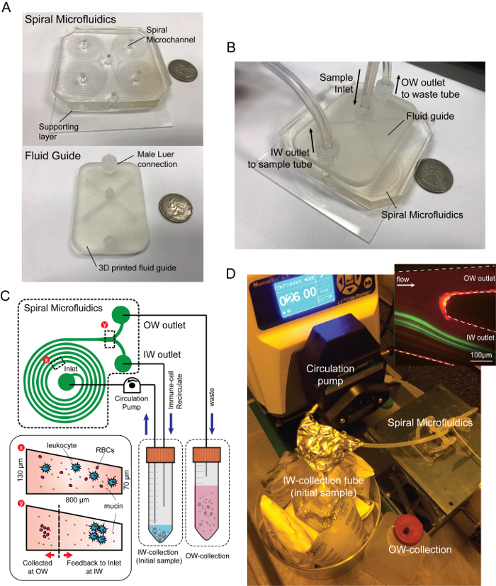
- Treat both the channel side of the device and plain PDMS with air plasma and bond with the prepared supporting layer of plain PDMS (Figure 1A).
- Place the chip on the 50 mm x 70 mm glass slide and place it in a 70 °C oven for at least 30 min to enhance the bonding strength.
2. Tracheal Secretion Collection from Mechanically Ventilated Patients
NOTE: Tracheal secretions can be obtained from mechanically ventilated patients during normal routine airway care by using a protocol modified from conventional methods to accommodate the standard, adult ventilated patient. Samples were de-identified and sent immediately for processing.
- If tracheal aspiration is indicated, use a catheter to extract airway secretions.
- Advance the catheter carefully halfway into the endotracheal tube and instill 5 mL of 0.9% sterile normal saline from a pre-filled 10 mL syringe.
- When the catheter is advanced fully, or resistance is met, aspirate the secretions and collect them into a sterile sputum collection container.
- Collect 10 mL of tracheal secretions in a sterile sputum container and place it on ice. Send samples immediately for processing.
3. Tracheal Secretion Sample Preparation
NOTE: All experiments must be performed under a biosafety cabinet with the proper personal protective equipment.
- Disperse 1 mL of airway secretion samples in 9 mL of phosphate-buffered saline (PBS) using a plastic 10 mL syringe (for a 10x dilution). Use a blunt pipette to homogenize the mucus sample.
- Strain the diluent with a 40 µm nylon cell strainer to remove large chunks or blood clots, which can block the microfluidics access hole or the channel. Place the sample on the ice after processing.
- Disperse the diluent of each sample using a 100x volume of PBS buffer, resulting in a 1,000x diluted suspension. Place the sample on the ice during the entire dissociation operation.
4. Experimental Setup
NOTE: All experiments must be performed under a biosafety cabinet with the proper personal protective equipment.
- Assemble the PDMS chip with the fluid guide to apply uniform flow to each of the four spiral microchannels (Figure 1B).
NOTE: Four channels were used to increase the throughput by parallelization, as well as optimization of the volume and cell density of the resulting suspension. The fluid guide is designed and made with a stereolithography-type 3D printer with clear resin. The inlet and the outlet port of the fluid guide use female Luer connectors for ease of connection and stable sealing during the operation.
- Connect a 1/16-inch male Luer connector to the inlet, the inner wall (IW) outlet, and the outer wall (OW) outlet port of the fluid guide and connect a silicone tubing to the sample suspension.
- Insert blunt tips to each end of the inlet and outlets to reach the bottom of the sample reservoir.
- Connect the peristaltic pump with the inlet tubing.
- Place the end of the inlet tubing and IW outlet tubing in the sample reservoir and place the end of the OW outlet tubing in the waste reservoir (Figure 1C, D).
- Place the 50 mL tube of filtered PBS without calcium and magnesium in the sample reservoir.
- Start pumping at a low flow rate (~1 mL/min) to prime the device.
NOTE: When bubbles are captured in the channel, push the top of the channel with the tweezer to destabilize and eliminate air bubbles. When the device is fully filled with buffer solution, change the PBS tube to prepare the airway secretion sample tube.
- When the sample is placed in the sample reservoir, switch on the peristaltic pump and set the flow rate at 4 mL/min (Figure 1C, D).
- When the sample volume reaches the designated volume (~1 mL), stop the operation and disconnect the silicone tubing.
NOTE: The proposed method is more efficient at reducing a large volume of diluent (>50 mL) into a micro-centrifuge tube volume (~1 mL) (Figure 2).