All procedures involving animal models have been reviewed by the local institutional animal care committee and the JoVE veterinary review board.
1. Microfluidic chamber or MFC preparation
- PDMS casting in primary molds (Figure 1)
- Purchase or create primary molds (wafers) following a detailed protocol.
- Use pressurized air to remove any type of dirt from the wafer platform before proceeding to the coating step. The surface of the wafers should look smooth and clear.
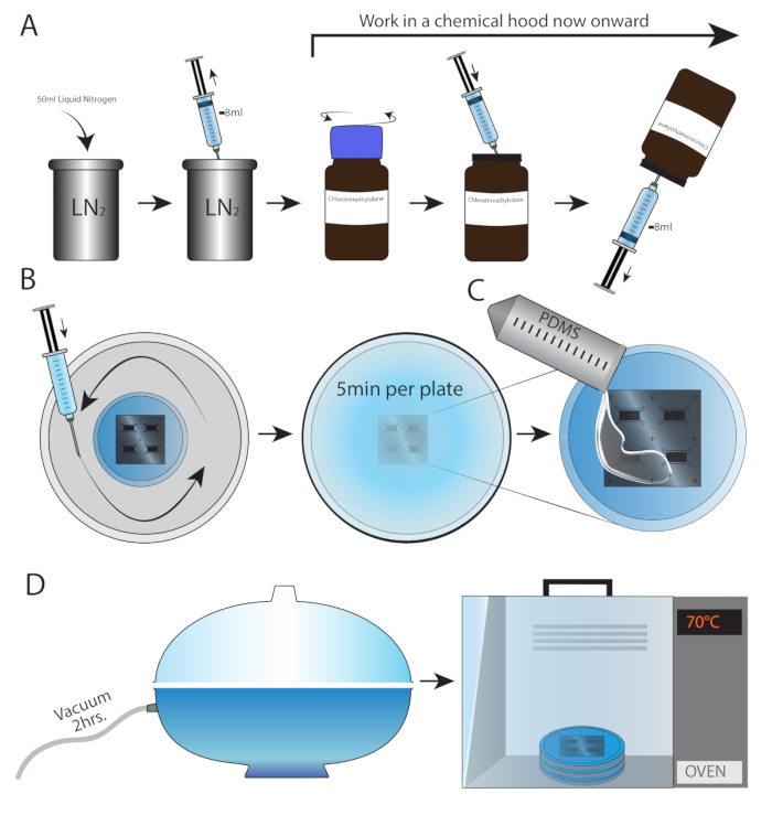
- Fill a container with 50 mL of liquid nitrogen. Prepare a 10 mL syringe and 23 G needle.
NOTE: All procedures from this step forward must be performed in a chemical hood.
- In the chemical hood, use the syringe and needle to pool 2 mL of liquid nitrogen. Though it may seem like the air was drawn, the syringe is filled with nitrogen (Figure 1A). Place the wafer-containing plate in a sealable container.
- Screw open a chlorotrimethylsilane bottle, pierce the rubber cap using the nitrogen-filled syringe, and inject the entire contents of the syringe into the bottle. Without pulling out the needle, turn the bottle upside down and draw back 2 mL of chlorotrimethylsilane.
NOTE: Because of the syringe pressure, a small amount of chlorotrimethylsilane is sprayed out of the needle. To avoid a hazard, point the needle toward the inner wall of the hood (Figure 1B).
- Spread chlorotrimethylsilane uniformly in the container (from step 1.1.4), but not directly on the wafer or wafer-containing plate. Close the container and incubate for 5 min per wafer.
NOTE: If this is the first time the wafer is coated with chlorotrimethylsilane, a 1 h incubation should be allowed for each wafer.
- Do not take the wafers and container out of the chemical hood for 30 min.
CAUTION: Chlorotrimethylsilane is highly volatile.
- Weigh the PDMS base (see Table of Materials) in a 50 mL tube and add the PDMS curing agent at a ratio of 16:1, respectively (e.g., 47.05 g of base and 2.95 g of curing agent). Mix for 10 min using a low-speed rotator.
- Pour PDMS into each wafer-containing plate to the desired height (Figure 1C).
NOTE: Using thin microfluidic chambers (up to 3-4 mm) improves adherence to the culture dish and prevents leakage.
- Place all plates together inside a vacuum desiccator for 2 h (Figure 1E). This process removes the air trapped within the PDMS, thus eliminating air bubbles and forming a clear, uniform mold.
- Place the plates inside an oven for 3 h (or overnight) at 70 °C (Figure 1E).
NOTE: The plates should be level when placed in the oven.
- PDMS casting in epoxy molds
NOTE: Because wafer preparation is expensive, requires special equipment, and may damage the fragile wafers, it is possible to generate epoxy replicas of wafers. The replicas are cheaper, more durable, and can be used for the mass production of microfluidic chambers.
- Cast and cure PDMS (as described in 1.1.8-1.1.11) into the original wafer.
- Remove and cut off excess parts of PDMS leaving only the microfluidic elements and the functional area required for processing them into microfluidic chambers.
- Immediately wrap the PDMS with thick, sticky tape to prevent it from accumulating dust.
- Choose a tissue culture-grade plastic dish that fits the entire PDMS inside and leave room for epoxy around it. The distance from the PDMS to the plastic dish should be less than 5 mm.
- Prepare a small amount of PDMS mixed in a ratio of 10:1 (base: curing agent). The fresh liquid PDMS will be used to glue the solid PDMS onto the bottom of the plastic plate.
- Apply a minimal amount of the liquid PDMS to the center bottom of the plastic plate and then remove the sticky tape from the PDMS and adhere it to the plastic dish bottom. Make sure that the microfluidic elements are facing upwards.
- Let the PDMS cure for 30 min in a 70 °C oven.
- Prepare the epoxy resin by mixing the base and curing agent in a ratio of 100:45, respectively in a test tube. Different epoxy resins may have different mixing ratios. The required volume for a regular 100 mm plate is approximately 40 mL.
- Let the epoxy mix well for 10 min in a rotator until the mixture becomes visibly homogenous (i.e., there are no visible fiber-like artifacts in the liquid).
- Centrifuge the epoxy mixture at 400 x g for 5 min to remove air bubbles caught inside.
- During centrifugation, spread a thin layer of silicone grease around the walls and all other exposed plastic parts of the culture dish. This will prevent the epoxy from polymerizing with the dish plastic and will enable the removal of the cured epoxy easily at the end of the protocol.
- Pour the epoxy slowly into the dish until it completely covers the PDMS and goes beyond it by at least 5 mm. Prevent the formation of any bubbles within the epoxy by keeping zero distance between the tube and the plate. Place the plate in a secure place so it will not be moved for the next 48 h.
- After 48 h the epoxy should be completely cured. Insert the plate into a preheated oven at 80 °C for 3 h for final curing.
- Remove the cured epoxy from the plate and the original PDMS mold by gently yanking the plastic wall of the plate until it breaks. It should then easily separate from the epoxy and peel off.
- Once extracted, wipe the remaining grease off the new epoxy replica and inset it upside down (i.e., with the replicated microfluidic elements facing up) into a new culture dish. The epoxy replica is now ready for PDMS casting.
- Use pressurized air or N2 to blow any remains of PDMS or dirt off the epoxy mold and rinse it 2x with isopropanol. Fill it a third time and incubate for 10 min on an orbital shaker plate. Rinse the mold again 3x with isopropanol and discard the remaining liquid. Blow dry with air or N2 or place in a 70 °C oven until dry.
NOTE: Follow safety procedures when working with and discarding isopropanol.
- Keep the mold plates closed until casting. Follow steps 1.1.8.-1.1.11.
- Punching and sculpting the PDMS into an MFC (Figure 2)
- Cut and remove the PDMS mold from the plate by following the (+) marks on the wafers using a scalpel. Do not use force, as the molds are fragile (Figure 2A).
- Follow the instructions drawn on the sketch to punch and cut the chambers depending on the experimental setup (Figure 2B-F).
- For spinal cord explant culture (Figure 2C, E), punch two 7 mm wells in the distal side of the large MFC. Locate the wells in a way that they will overlap with the channel edges. On the proximal side, punch one 7 mm well in the middle of the channel, with minimal overlap, such that sufficient space will be left for the explants. Punch two additional 1 mm holes in the two edges of the proximal channel. Turn the MFC with the microfluidic elements facing upwards, and using a 20 G needle, carve three small explant caves on the punched 7 mm well.
- For dissociated MN culture (Figure 2D, F), punch four 6 mm wells in the edges of the two channels of a small MFC.
- Sterilizing the MFC for tissue culture use
- Spread 50 cm long sticky tape bands on the bench. Press and pull back the chamber to face the sticky tape (both upper and lower faces) and remove crude dirt. Place the clean chambers in a new 15 cm plate.
NOTE: Do not press directly on the microfluidic elements when these are facing upwards.
- Incubate the chambers in analytical grade 70% ethanol for 10 min on an orbital shaker.
- Dispose of the ethanol and dry the chambers in a tissue culture hood or in an oven at 70 °C.
- Placing the MFC on a glass bottom dish
- Place the chamber in the center of a tissue culture grade 35 mm/50 mm glass bottom dish and apply minor force on the edges to make the PDMS and dish bottom bind. To avoid breaking the glass bottom, always apply force on top of a solid surface.
- Incubate for 10 min at 70 °C. Press the chambers to strengthen adherence to the plate.
- Incubate under UV light for 10 min.
- Coating and culturing
- Add 1.5 ng/mL poly-L-ornithine (PLO) to both compartments. Make sure the PLO is running through the channels by pipetting the coating media a few times directly in the channel entrance.
- Examine the microfluidic chamber under a light microscope with 10x magnification to check for the presence of air bubbles. If air bubbles are blocking the microgrooves, place the MFC in a vacuum desiccator for 2 min. Later, remove the excess air that got caught in the channels by pipetting the coating media through them. Incubate overnight.
- Replace PLO with laminin (3 µg/mL in DDW) for overnight incubation in the same manner.
- Prior to plating, wash the laminin with a neuronal culture medium.
2. Neuronal culture plating
- Spinal cord explant culture
- Using straight scissors and fine forceps, dissect a spinal cord out of an E12.5 ICR-HB9:GFP mouse embryo. Work in a 1X HBSS solution with 1% penicillin-streptomycin (P/S) (Figure 3A-C).
- Using microdissection scissors, remove the meninges and the dorsal horns (Figure 3D).
- Cut the spinal cord into 1 mm thick transverse sections (Figure 3E). Dispose of all medium from the proximal compartment of the MFC.
- Pick up a single spinal cord explant with a pipette in a total volume of 4 µL. Inject the explant as close as possible to the cave and draw out any excessive liquid from the proximal well via the lateral outlets (1 mm punches). The explants should be sucked into the proximal channel.
- Slowly add 150 µL of spinal cord explant medium (SCEX, see Table of Materials and Table 3) to the proximal well.
- Spinal cord explant culture maintenance
- Add SCEX medium in the proximal compartment and rich SCEX medium (SCEX with 50 ng/mL of BDNF and GDNF) in the distal compartment. Maintain a volume gradient of at least 15 µL per well between the distal wells (higher volume) and the proximal well.
- Refresh the medium every 2 days. It can take the axons up to 3-5 days to cross distally.
3. Axonal transport (Figure 4A)
- Labeling of mitochondria and acidic compartments
- Prepare fresh SCEX medium (or CNB for dissociated MN) containing 100 nM Mitotracker Deep Red FM and 100 nM LysoTracker Red. Incubate for 30-60 min at 37 °C. Other colors can be used as long as their fluorophores do not overlap.
- Wash 3x with warm CNB/SCEX medium. The plates are ready for imaging.
- Live imaging
- Acquire 100 time-lapse image series of axonal transport at 3 s intervals, with a total of 5 min per movie.
NOTE: The imaging system used in this study included an inverted microscope equipped with spinning disc confocal, controlled via propriety cell imaging software, 60x oil lens, NA = 1.4, and an EMCCD camera. Movies were acquired in a controlled environment at 37 °C and 5% CO2.
NOTE: Longer or shorter time-lapse movies can be imaged, depending on the experiment. Even overnight movies can be recorded if needed. However, it is critical to try and reduce the exposure time and laser power, as well as the number of total images, to decrease phototoxicity and bleaching during movie acquisition.