Een abonnement op JoVE is vereist om deze inhoud te bekijken. Log in of start vandaag met uw gratis proefperiode.

Methodenartikel

Electrophysiological Recording of Voltage Responses of Drosophila Retinal Photoreceptors to Light Stimuli

877 weergaven

8 juli 2025

In dit artikel

Samenvatting

Source: Juusola, M., et al. Electrophysiological Method for Recording Intracellular Voltage Responses of Drosophila Photoreceptors and Interneurons to Light Stimuli In Vivo. J. Vis. Exp. (2016).

This video outlines the protocol for electrophysiological recording of photoreceptor activity in the eye of an immobilized Drosophila, enabling precise measurement of voltage changes in response to light stimuli.

Protocol

1. Recording from R1-R6 Photoreceptors

  1. Always be grounded when operating the microelectrode amplifier (for example by touching the metal surface of the Faraday cage or antivibration table), as this precludes one from accidentally delivering a static charge to the head-stage, which could damage the circuitry.
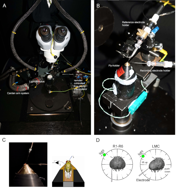
  2. Illuminate the fly preparation platform pole from above with two gooseneck light guides (Figure 1A) (with the cold light source inside the Faraday cage) so that the fly-holder can be placed on the pole in the preferred position under close visual control.
  3. Mount the fly-holder (with the fly in it!) on the fly preparation platform pole. Rotate the fly-holder so that the fly's left eye is directly facing the investigator (Figure 1B).
  4. Insert the blunt reference electrode gently through the fly's ocelli into the head capsule using a small coarse micromanipulator while observing the preparation through the stereomicroscope (Figure 1C). Do not push the electrode too deep, as this can damage the fly brain.
    1. Alternatively, insert the reference electrode into the back of the thorax. Always ensure that the fly appears healthy (moves its antennae), and its eyes are intact, not accidentally damaged. If the preparation looks less than immaculate, prepare a new fly for the experiments.
  5. Drive the sharp recording microelectrode into the left eye through a petroleum jelly covered small opening. Use high magnification in the stereomicroscope and move the light guides and the focal plane so that the electrode tip location becomes apparent in 3D by its reflectance patterns.
    NOTE: Figure 1D shows how the fly's head should be positioned (with respect to the angle at which the recording microelectrode enters the eye) for photoreceptor recordings. Driving the electrode into the eye without breaking it is the most difficult phase of the experiment. If the electrode tip misses the small opening in the eye, hitting the cornea, it typically breaks.
  6. Turn on the microelectrode amplifier once both electrodes are firmly inside the preparation, in electrical contact with the fly's body fluids.
  7. Turn off the cold-light source (inside the Faraday cage) and unplug it from the mains. Connect its plug to the central ground to minimize ground-loop induced electrical noise and move the goose-neck light guides away so the Cardan-arm system can be freely moved around the fly. Switch off the room lights to ensure that the fly preparation is now in relative darkness.
  8. Measure the resistance of the recording electrode in the eye. Use only recording electrodes in which resistance is 100 - 250 MΩ.
    NOTE: Achieving high-quality intracellular recordings by <70 MΩ electrode is virtually impossible. If the resistance is <80 MΩ, it is likely that the electrode tip is broken. In this case, switch off the amplifier and change the recording electrode.
  9. Set the amplifier to current-clamp (CC) or bridge recording mode. Cancel out any arbitrary voltage difference between the recording and reference electrodes, as both are now resting in the electrically interconnected extracellular space, by setting the signal offset (recording voltage) to zero. Follow the signal offset changes using the amplifier's display readout or an oscilloscope screen.
  10. Wait 2-3 min for the fly eye to dark-adapt.
  11. Drive the recording electrode tip deeper into the eye with small 0.1 to 1-micron steps. Do this with an x-axis piezo-stepper of a remote-controlled micromanipulator or by gently rotating the fine-resolution knob of a manual manipulator.
  12. Stimulate the fly eye with brief (1 - 10 msec) light flashes as the recording electrode is being advanced in the tissue.
    NOTE: If the recording electrode is positioned in the retina and the eye functions normally, each light flash will cause a brief and small drop in the voltage (0.2 - 5 mV hyperpolarization), called the electroretinogram (ERG). This change in the field potential of the extracellular space is caused by the retinal cells' collective response to light.

Toegang beperkt. Log in of start een proefperiode om deze inhoud te bekijken.

Resultaten

Electrophysiology setup for light stimulation in flies, diagrams show electrode positioning.
Figure 1. Positioning the Fly-holder and the Electrodes for the Experiments. (A-B) The fly-holder is placed on the recording platform that also provides temperature control via a Peltier element (A: white round platform in the center). The Cardan-arm enables ex...

Toegang beperkt. Log in of start een proefperiode om deze inhoud te bekijken.

Openbaarmakingen

No conflicts of interest declared.

Materialen

Lijst van materialen gebruikt in dit artikel
NaamBedrijfCatalogusnummerOpmerkingen
Stereo Zoom Microscope for making the fly preparationOlympusSZX12 DFPLFL1.6x PF eyepieces: WHN30x-H/22Capable of ~150X magnification with long working distance; bespoke heavy steel table mount stand
Stereomicroscope in the intracellular set-up· OlympusOlympus SZX7; eyepieces: WHN30x-H/2230X eyepieces are needed for seeing the electrode tip reflections well when driving it through the small corneal hole into the eye
Nikon microscopeNikon SMZ645; eyepieces: C- W30x/7
Anti-vibration TableMelles GriotWith metric M6 holes on the breadboardOur bespoke rigs have a large hole drilled through the thick breadboard that lets in the fly preparation platform pole (houses a copper heatsink with electronics) from below
Newport
MicromanipulatorsNarishigeNarishige NMN-21In our intracellular set-ups, different micromanipulator systems are used for driving the shap recording electrodes into the fly eye. All the listed manipulators are succesfully providing long-lasting stable recordings from Drosophila photoreceptors and LMCs.
Huxley BertramHuxley xyz-axis with fine manual control
SensapexSensapex triple axis
MärzhäuserMärzhäuser DC-3K with additional x-axis piezo stepper and MS 314 controller
Magnetic StandsAny magnetic base with on/off switch will doFor example, to manage cables inside the Faraday cage
Electrode HoldersHarvard ApparatusESP/W-F10N
Silver WireWorld Precision InstrumentsAGW15100.3 - 0.5 mm diameter; needs to be chloridized for the electrode holders
Fiber Optic Light SourceMany different, including Olympus
Fiber Optic BundlesUltraFine TechnologyTo deliver the LED light stimulus to the Cardan arm system. We use both liquid and quartz light guides (range from UV to IR)
Thorn Labs
Fly Cathing TubeP80-50P 50ml Cent. Tube PP., Pack of 100 PcsCut the conical bottom off from 50 ml Plastic Centrifuge Tube and glue a 1 ml pipette tip on it.
Digital Acquisition SystemNational Instruments
Single-electrode current/voltage- clamp microelectrode amplifiernpi SEC-10LXhttp://www.npielectronic.de/ products/amplifiers/sec-single- electrode-clamp/sec-10lx.htmlOutstanding performer!
Head-stageStandard (+/- 150 nA)For npi SEC-10LX
LED light sources and drivers2-channel OptoLED (Cairn Research Ltd., UK)Many of our stimulus systems are in-house built
Self-designed and constructed
Acquisition and Analyses SoftwareMany companies to choose fromBiosyst; custom written Matlab- based system for experimental and theoretical work in the Juusola laboratory
Personal Computer or MacEnsure that PC or Mac is compatible with data acquisition system and software
Cardan arm systemSelf-designed and constructedProviding accurate x,y,z-positioning of the light stimuli
Peltier temperature control systemSelf-designed and constructed
Faraday CageSelf-constructedElectromagnetic noise shielding
Filamented Borosilicate Glass CapillariesOuter diameter: 1 mm
Inner diameter: 0.5 - 0.7 mm
Filamented Quartz Glass CapillariesOuter diameter: 1 mm
Inner diameter: 0.5 - 0.7 mm
Pipette PullerSutter Instrument CompanyModel P-2000 laser Flaming/Brown Micropipette PullerFor borosilicate reference electrodes, use the preset program #11 (patch electrodes): Heat = 350;
Filament = 4; Velocity 36; Delay
= 200).1.2.1). For borosilicate recording electrodes, use the preset program #12 (this typically pulls good conventional sharps for photoreceptor recordings): Heat = 355; Filament = 4; Velocity 50; Delay = 225; Pull = 150. For LMC recordings, which require electrodes with finer tips, these values need to be adjusted. For pulling quartz capillaries, P-2000 manual suggests programs for
fine tipped microelectrodes. These programs’ preset parameters serve as useful starting points
for systematic modifications to generate electrodes with good penetration success and low recording noise.
Extracellular Ringer Solution for the reference electrodeChemicals from Fisher Scientific10326390, NaCl 10010310, KCl
10147753, TES 10161800, CaCl2
10159872, MgCl2 10000430,
sucrose
See the recipe in the protocol section
3 M KCl solution for filling the filamented recording microelectrodeSalts from Fisher Scientific10010310, KCl
Petroleum jellyVaselin

Tags

Drosophila fotoreceptorenintracellulaire spanningretina van het netvliesmicro elektrodeversterkerdarkadaptatieionkanalenmembraanpotentiaalflitsstimulatie