Een abonnement op JoVE is vereist om deze inhoud te bekijken. Log in of start vandaag met uw gratis proefperiode.

Methodenartikel

An In Vitro Model of Stretch Injury in Human Induced Pluripotent Stem Cell-Derived Neurons

724 weergaven

8 juli 2025

In dit artikel

Samenvatting

Source: Phillips, J. K. et al. Method for High Speed Stretch Injury of Human Induced Pluripotent Stem Cell-derived Neurons in a 96-well Format. J. Vis. Exp. (2018)

This video demonstrates the process of inducing stretch injury on human induced pluripotent stem cell-derived neurons (hiPSCNs). The cells are taken in a bottomless multi-well plate with a silicone membrane attached. Controlled mechanical stress is applied on the membrane to induce cytoskeletal disruption and cell membrane damage, inducing a stretch injury phenotype in the cells.
Protocol

1. Plate Fabrication

  1. Plasma-treat a 96-well plate top with a 200 W plasma cleaner (see Table of Materials) for 60 s on high power, placing it bottom-side-up inside the plasma cleaner. Check for a purple glow visible through the window of the chamber, which indicates that an effective plasma has formed. This bonding technique is adapted from Sunkara et al.
  2. Within 60 s, place the plate top in 200 mL of 1.5% (3-Aminopropyl) triethoxysilane (APTES) in deionized (DI) water for 20 min, bottom-side-down. This solution is unstable: prepare it no more than 60 s before introducing the plate.
    CAUTION: Work with APTES in a fume hood.
  3. Plasma treats an extracted silicone membrane in the plasma cleaner for 60 s on high power. Time the plasma treatment such that it finishes no more than 5 min before the end of the 20 min period in step 1.2.
  4. Use forceps to position the plasma treated membrane on top of a 7.5 x 11 cm2 parchment paper rectangle. Align a 7.5 cm x 11 cm x 0.5 cm aluminum slab on the lower portion of the plate fabrication clamp. Align the silicone membrane and parchment paper on the aluminum slab using forceps.
  5. Remove the plate tops from the APTES bath and shake off excess solution. Dip into a 200 mL DI water bath for 5 s and shake off excess water. Dip into a different 200 mL DI water bath for 5 s and shake off excess water. Replace the water in these baths before dipping another plate top.
  6. Use compressed air to completely dry the plate top.
  7. Place the plate top in the upper portion of the plate fabrication clamp. Gently close the plate fabrication clamp to press the plate top and silicone together. Clamp for at least 1 h.
  8. Allow the plate to cure for 24 h at room temperature before use, protected from dust.

2. Stretching a Plate

  1. Clean the indenters
    1. Prepare a 60 W bath-style sonicator with DI water at room temperature.
    2. Support the indenter block above the sonicator bath, inverted so that only the tops of the indenters are submerged to a depth of at least 1 mm. Sonicate the indenters for 8 min at 42 kHz.
    3. Blow dry the indenters with compressed air.
  2. Align the indenter block
    1. Position a camera with a live feed above the stretching device so that it is looking down on the indenter array. Focus on the tops of the indenters.
      NOTE: The setup described in Section 3, "Characterizing Membrane Stretch," is one possible camera setup for this task.
    2. Secure a plate on the stage of the injury device using the stage clamps (Figure 1) and place a dome light over the device.
      NOTE: See the Table of Materials for the instrument control software.
    3. Launch the instrument control software by clicking on the software icon on the desktop of the computer that is controlling the injury device. Run the "in_vitro_neurotrauma.lvproj" project by clicking on it in the launch window. From the project window, launch the motion control and position tracker virtual instruments (VIs), which are named 'motion_control.vi' and 'position_tracker.vi', respectively, by double-clicking on them.
    4. Close the cage surrounding the injury device. Press the 'arrow' button in the top left corner of the motion control VI to run the VI and click 'Near Bottom' to lower the stage to within 2 mm of contacting the indenters. Click the 'Stop' button to stop the VI.
      Caution: Keep hands clear of the stretcher when manipulating the camera in the cage. The cage should be fitted with a door switch that delivers power to the stretching device only when the cage door is closed.
    5. In the project window, right click on 'Axis 1'. Click on 'Interactive Test Panel'. In the window that opens, set the step size to 50 µm by entering '500' units in the 'Target Position' field.
    6. Click the green 'go' button at the bottom of the 'Interactive Test Panel' window repeatedly until the plate first makes contact with any indenters. Check for contact on the live image displayed by the camera. Note the vertical stage position reported in the top left of the 'Interactive Test Panel' window; this is the first contact position.
    7. Lower further (as described in step 2.2.6) until every well has made contact with the indenters. If necessary, move the camera to see the whole plate and move the stage up (by specifying a negative 'Target Position') and down. Note the vertical stage position reported in the top left of the window when all posts are in contact (this is the full contact position).
    8. Note the difference between the first contact and full contact positions. Close the 'Interactive Test Panel'. Run the 'motion control VI' (see step 2.2.4) and click on 'Top' to raise the stage. Stop the motion control VI with the 'Stop' button.
    9. Once the stage is at the top of its travel, open the door to deactivate the device. Adjust the set screws on the corners of the indenter block. Loosen the set screw on the corner that made contact first, to lower it and tighten the opposite screw to raise the corner that made contact last.
    10. Repeat the process of lowering the stage until the plate contacts the indenters, inspecting the contact images for tilt, raising the stage, and adjusting (step 2.2.9) the indenter block. When the stage and block are aligned, all indenters will make contact at once.
    11. Open the door to deactivate the device. Insert the tie-down screws into their holes on the indenter block and tighten them. Confirm that the block is level with the tie-down screws in place (steps 2.2.4-2.2.8). Take note of the stage position reported by the 'Interactive Test Panel' when the plate makes contact. This will be the zero position for indentation experiments.
  3. Lubricate the indenters
    1. If the indenter block has just been set up and has not yet been lubricated, clean a solid rubber pad (7.5 cm x 11 cm x 1.5 mm) and a soft, closed-cell foam rubber pad (7.5 cm x 11 cm x 3 mm) with an ethanol-soaked lab wipe. Allow them to air dry.
    2. Soak a lab wipe in corn oil and spread it on the solid rubber pad to a dull shine.
    3. Place the foam pad onto the solid rubber pad to transfer oil to the foam pad. Place a 7.5 cm x 11 cm x 0.5 cm aluminum slab on top of the foam pad and load it with a ballast weight of approximately 360 g (e.g., 6 conical tubes loaded with 45 mL of water each) to ensure consistent transfer of oil from the solid rubber pad to the foam pad. Allow 10 s for the oil to transfer to the foam rubber pad.
    4. Move the foam rubber pad onto the indenter array. Place the aluminum slab and the ballast weight on top of it to ensure consistent transfer of the oil to the tips of the indenters. Allow 10 s for the oil to transfer to the indenters.
    5. If no plate has been stretched since the indenter block was set up and lubricated for the first time, stretch a test plate before beginning the experiment. Note: This will prevent any inconsistency between the first stretch and subsequent stretches from confounding the experiment. For subsequent stretches, repeat only steps 2.3.2-2.3.5 before each stretch.
  4. Stretch a plate
    1. Lubricate the indenters as described in step 2.3.
    2. Secure the plate on the stage of the injury device with the stage clamps. If sterility is required, adjust the position of the lid to secure the plate without exposing the culture surface to room air.
    3. Lower the stage to the zero-position using the 'motion control VI' (see steps 2.2.4-2.2.6); zero-position is determined during step 2.2.
    4. Change the file name in the "file path" field in the 'position tracking VI' to a unique file name, then run it with the 'arrow' button in the top left corner of that window.
    5. Set the depth and duration of indentation (typically 1-4 mm and 30 ms, respectively, maximum depth 5 mm, minimum duration 15 ms) in the 'Injury (mm)' and 'Injury Duration (ms)' fields in the 'movement control panel VI' by clicking on the fields and typing in the desired values.
    6. Run the 'movement control panel VI' and click on 'Injure' to indent the plate.
    7. Move the stage up to the top of its travel by clicking on 'Top'. Then stop the VI with the 'Stop' button and deactivate the injury device by opening the door.
    8. Inspect the displacement history of the stage presented in the 'position tracker VI' to confirm that the specified maximum displacement was applied. Right click on the graph and click on 'export to Excel'. Click on 'File| Save' to save the data.

3. Characterizing Membrane Stretch

  1. Paint the recess at the top of each indenter white to provide a high contrast background for high-speed videography. Caution: Do not paint the rims of the indenters where they make contact with plates.
  2. 3D print with poly(lactic acid) (PLA), or otherwise fabricate, a cylindrical stamp with which to make a dot in each well. Make the cylinder 5.9 mm in diameter and 12.2 mm high, with a cylindrical protrusion 1.5 mm diameter and 1.0 mm high centered on top.
  3. Plasma treats the plate right-side-up to activate the silicone cell culture surface in the wells for 60 s, as mentioned in step 2.1.
  4. Place the plate on a rubber pad or other soft surface. Prime the small protrusion on the stamp (see step 1.2) with ink from a permanent marker pen. Insert the stamp into the well to be tested and tap to ensure good transfer of ink. Prime the stamp before every well.
  5. Align the indenter block and lubricate the indenters of the injury device (see steps 2.2-2.3). Clamp the plate onto the stage of the injury device. Position a bright diffuse axial light above the injury device.
  6. Set up a high-speed camera on a boom stand over the injury device, facing straight downward, with the lens set to the smallest numbered f-stop, and turn it on. Launch the camera software on the computer connected to the camera. In the frame rate drop down menu, select 2,000 frames per second, and in the shutter drop down menu, select the fastest exposure time which yields high contrast images. Center over the dotted wells.
    1. Position the camera so that the field of view contains 12 wells in a 3 x 4 grid.
      NOTE: This field of view offers an optimal compromise between throughput and resolution for a 1,280 × 1,024 image.
  7. Lower the plate to the zero-point (see steps 2.2.4-2.2.6). One-click the record button on the camera software so that it reads 'trigger in'. Initiate the position tracker VI (step 2.4.4).
  8. Turn on the bright diffuse axial light. Indent the plate as described in step 2.4.6.
  9. Turn off the bright diffuse axial light.
  10. On the camera control computer, find the 30-40 ms window of the recording in which the indentation occurs: drag the beginning and end arrows in the high-speed video play bar in the camera software. Click Save, set the name in the 'File Name' field, select 'TIFF' in the 'Format' field, and click on 'Save'.
    1. Look through the .TIF-files for images of the least stretched (beginning) and most stretched (peak indentation) states.
    2. To measure the height and width of the dots in both images, use Fiji to open the images of the least and peak stretch side-by-side. Using the default rectangular selection tool, click and drag to draw a box around a dot in the least stretch image. Measure the height and width with 'Analyze| Measure'.
    3. Repeat for the dot in the same well on the peak stretch image. Repeat for the rest of the wells.
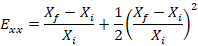
  11. Calculate the Lagrangian strain in the x and y directions as follows:
    Eqn showing relative error: Exx = (Xf-Xi)/Xi + 1/2(Xf-Xi/Xi)^2; formula analysis
    NOTE: Here, Exx is the Lagrangian strain in the x direction, Eyy is the Lagrangian strain in the y direction, X is the width of the dot, Y is the height of the dot, f denotes the final image (i.e., the peak indentation image), and i denotes the initial image (i.e., the pre-indentation image). Average the two values to determine the strain in that well.

4. Plating the Cultured Cells

  1. Autoclave the bins and ballast weights that will be used for sterilization.
  2. Plasma treat the silicone-bottomed plates right-side-up for 60 s (see step 1.1). Immediately submerge the plates in sterile bins containing 70% ethanol for 15 min.
  3. Submerge the plates in sterile phosphate buffered saline (PBS) in separate sterile bins for 30 min.
  4. Aspirate the PBS from the wells. Only dry one plate at a time to prevent the wells from losing the plasma treatment.
    Caution: Silicone bottomed plates provide less tactile feedback than rigid plates when pipetting and are more likely to block the tip of a pipette.
  5. Add 100 µL of 0.1 mg/mL poly-L-ornithine (PLO) per well to the sterilized plates. Incubate at room temperature for 1 h.
  6. Rinse the wells twice with 100 µL sterile PBS, leaving the second wash on the wells until the cell suspension is ready.
  7. Remove the vial of hiPSCNs from liquid nitrogen storage using safety gloves and place on dry ice. Quickly transport the vial to a 37 °C water bath and thaw for exactly 3 min. Do not swirl the vial.
  8. In a sterile hood, gently transfer the contents of the vial to a 50 mL conical tube using a 1 mL serological pipette.
  9. Rinse the empty cryogenic vial with 1 mL of room temperature complete maintenance medium (media base + supplement).
  10. Transfer the 1 mL of media into the 50-mL tube dropwise at about one drop per second. Gently swirl the tube while adding. Add 8 mL of room temperature complete maintenance medium to the 50 mL tube at about 2 drops/s.
  11. Cap the tube and invert 2-3 times. Count the cells with a hemocytometer. Compute the volume of the additional media required to dilute the cell suspension to 225,000 cells/mL.
  12. Gently pipette the amount of media (calculated above) into the tube of cell suspension using a 25 mL serological pipette.
  13. Add 10 µL of 1 mg/mL laminin stock per 1 mL of cell suspension with a 1,000 µL micropipette to achieve 10 µg/mL of laminin in the cell suspension. Aspirate up and down once with the tip used for laminin, then cap the tube and invert the tube once.
  14. Aspirate the PBS from the plates, one plate at a time. Use a multichannel pipette to add 100 µL of the hiPSCN cell suspension to each well. The wells have a culture area of 0.33 cm2, so the cell density per area is 67,500 cells/cm2.
  15. Rest the plates at room temperature for 15 min after seeding to promote attachment. To avoid fan vibrations of sterile culture hood, place the covered plates on the lab bench. Incubate the cultures at 37 °C with 5% CO2.
  16. Perform a full media change at 24 h, refilling the wells with 200 µL of complete maintenance media. Perform a half media change of 100 µL/ well every 2-3 days.

5. Injuring Cultures

  1. Align the indenter block and find the zero position as described in step 2.2. Lubricate the indenters as described in step 2.3.
  2. Set the filename for the displacement history in the 'position tracker VI' (step 2.4.4). Set the injury parameters in the 'motion control VI' (step 2.4.5).
  3. Take the plate to be injured out of the incubator and clamp it onto the stage. Adjust the position of the lid to secure the plate without exposing the cultures to room air.
  4. Lower the plate to the zero-point (steps 2.2.4-2.2.6) using the 'motion control VI'. Start the 'position tracker VI' (step 2.4.4).
  5. Use the movement control VI to indent the plate (as described in step 2.4.6). For sham stretches, skip only this step.
  6. Return the stage to the top of its range of motion (see step 2.4.7). Return the plate to the incubator.
  7. Inspect and save the displacement trace (as in step 2.4.8).

Toegang beperkt. Log in of start een proefperiode om deze inhoud te bekijken.

Resultaten

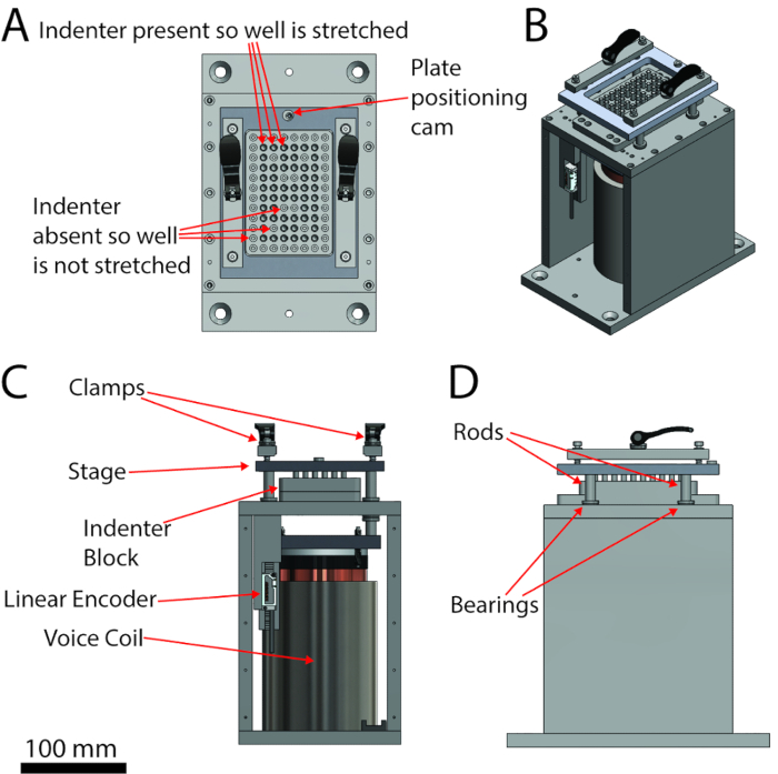
Biomechanical testing device diagrams showing indenter, encoder, coil, used in material analysis.
Figure 1: A labeled schematic of the injury device. (A) Top view, (B) isometric view, (C) front view, (D) right side view. The scale bar applies to the orthographic views (A, B and D).

Toegang beperkt. Log in of start een proefperiode om deze inhoud te bekijken.

Openbaarmakingen

No conflicts of interest declared.

Materialen

Lijst van materialen gebruikt in dit artikel
NaamBedrijfCatalogusnummerOpmerkingen
.010" Silicone SheetSpecialty Manufacturing, Inc #70P001200010Polydimethylsiloxane (PDMS) sheet
SparkleenFisher Scientific#043204
Nunc 256665Fisher Scientific#12-565-600Bottomless 96 Well Plate
Kim WipesULINES-8115
Plasma CleanerHarrick Plasma#PDC-001-HC
(3-Aminopropyl) triethoxysilaneSigma-Aldrich#440140APTES
Parchment PaperReynoldsN/A
Dome LightCCS incLFX2-100SW
Dome Light Power SupplyCCS incPSB-1024VB
Axial Diffuse Lighting UnitSiemensNerlite DOAL-75-LEDDiffuse axial light
High Power LED ArrayCREEXLamp CXA2540High Power LED Array
LED holderMolex1807200001LED Holder
LED power supplyMean WellHLG-320H-36BConstant Current Power Supply
FastCam Viewer softwarePhotroncamera softeware
Fastcam Mini UX50PhotronN/AHigh Speed Camera
Micro-NIKKOR 105mm f/2.8Nikon#1455High Speed Camera Lens
0.1 mg/mL Poly-L-OrnithineSigma-Aldrich#P4597
iCellsCellular Dynamics International#NRC-100-010-001
iCell mediaCellular Dynamics International#NRM-100-121-001
iCell supplementCellular Dynamics International#NRM-100-031-001
LamininSigma-Aldrich#L2020
voice coil actuatorBEI KimcoLA43-67-000A
optical linear encoderRenishawT1031-30A
servo driveCopley ControlsXenus XTL
ControllerNational InstrumentscRIO 9024 Real Time PowerPC Controller
cRIO chassisNational InstrumentscRIO 9113
digital input moduleNational InstrumentsNI 9411
data acquistion chassisNational InstrumentsNI 9113
LabVIEWNational Instruments
hiPSCNsCellular Dynamics International

Trefwoorden

Toepassing van mechanische stressverstoring van het cytoskeletbeschadiging van het celmembraandegeneratie van neurietencoating van siliconenmembraanbodemloze multi well plaatbediening van het beschadigingsapparaatvirtueel instrument voor positiebepaling