In this video, we demonstrate the use of spectral-domain optical coherence tomography (SD-OCT) to image retinal layers and assess structural changes in a genetically modified mouse model with optic neuropathy.
Een abonnement op JoVE is vereist om deze inhoud te bekijken. Log in of start vandaag met uw gratis proefperiode.
Methodenartikel
In Vivo Imaging of the Mouse Retina Using Optical Coherence Tomography
1.4K weergaven
⸱
29 mei 2025
In dit artikel
Samenvatting
Protocol
All procedures involving animal models have been reviewed by the local institutional animal care committee and the JoVE veterinary review board.
1. Mouse Preparation
- Eye dilation and immobilization
- At least 15 min before data acquisition, instill 10% phenylephrine eye drops into the mouse eyes, remove the excess, and instill 0.5% tropicamide eye drops.
NOTE: The first dilatation can be done at once for all the mice that will be tested in the session. Make sure that the liquids are at room temperature. - Immediately after inducing general anesthesia (step 1.2), administer 0.4% oxybuprocaine hydrochloride eye drops, keeping them in place for 3 s to anesthetize and immobilize the eyes. Afterwards, wipe off the drops and repeat the instillation of 10% phenylephrine and 0.5% tropicamide to ascertain that the eyes are well dilated.
NOTE: Make sure that the liquids are at room temperature and that the mouse does not swallow the oxybuprocaine.
- At least 15 min before data acquisition, instill 10% phenylephrine eye drops into the mouse eyes, remove the excess, and instill 0.5% tropicamide eye drops.
- General anesthesia
- Prepare an anesthetic solution of ketamine (20 mg/mL) and xylazine (1.17 mg/mL) in saline. Store at 4 °C for a maximum of 2 weeks.
- Approximately 5 min before testing, intraperitoneally inject 5 - 10 µL of anesthetic solution per 1 g of body mass, depending upon the age and size of the mouse.
NOTE: Young and/or thin mice need less anesthetic, take less time to anesthetize, but also awaken faster. Here, 8 µL/g (160 mg/kg of ketamine, 9.33 mg/kg of xylazine). - Optionally, lubricate the eyes with viscous eye drops or an ophthalmic gel to avoid corneal dryness.
2. Mouse Positioning
- Lubricate the eyes with viscous glycol-based eye drops to provide corneal hydration.
NOTE: If the eyes seem dry during the exam, re-apply the eye drops. - Wrap the mouse in a sheet of surgical gauze to keep it warm.
- Using a sponge or cotton wick, apply a thin layer of an ophthalmic gel with 0.3% hypromellose onto each eye, to minimize light refraction, avoid opacities, and secure corneal hydration. While doing so, move the eyelashes and whiskers aside.
- Position the mouse in the cassette, with the head straight and pointing forward.
- Gently open the bite bar clamp and place the bar in the mouth; use the nose band to secure the position.
NOTE: Ensure that the bite bar is in the middle of the cassette. - Place a cotton roll under the right (left) side if the right (left) eye is being tested.
- While keeping the clip-on aiming tip on the mouse-specific lens, bring it towards the eye by rotating the Z-translator screw counterclockwise.
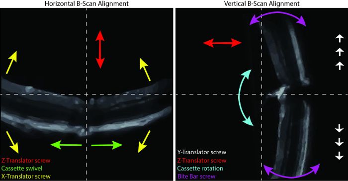
- By rotating and swiveling the cassette and by turning the bite bar and the X-translator screws, pre-set the position of the mouse; the goal is to have the right eye look directly into the lens, and thus to align the optical axes of the eyes and the lens.
NOTE: If the mouse is too high or too low, the Y-translator screw should be used first. - Choose the first scan in the "Exam", click on "Start Aiming", and make any further manual adjustments for retinal imaging.
- Using the Z-translator screw, move the retina vertically on the left panel (Figure 1, Horizontal B-scan Alignment) and horizontally on the right panel (Figure 1, Vertical B-scan Alignment).
- Rotate the cassette to bring the ONH in the middle of the right panel by moving the ONH up or down. Use the bite bar screw to straighten the retina on the right panel. Swivel the cassette to position the ONH in the middle of the left panel.
- Use the X-translator screw to level the retina on the left panel. Keeping in mind the major function of each modulator, further adjust the position of the retina to centralize the ONH.
NOTE: Use the Y-translator screw to move the ONH up and down on the right panel, if necessary. The position may be refined at any time between scans.
3. SD-OCT Imaging of the ONH and Retina
- Once content with the adjustments, click on "Start Snapshot" to begin SD-OCT scanning.
- If a 3D imaging is not required, uncheck the OCU option.
- Save the scan and the report.
- Proceed with the next scans.
- To image the second eye, after retracting the lens, turn the cassette accordingly and repeat steps 2.6 - 3.3.
4. Acquisition Completion
- When the acquisition is complete, remove the mouse from the cassette, apply ophthalmic gel with 0.3% hypromellose to each eye, and place the mouse on a heating plate to wake up.
- After the last acquisition, close the software and switch off the computer and the OCT machine (power supply button).
- Clean the cassette with disinfectant.
5. Analysis
- For the retinal layer thickness measurement, use the automated segmentation software provided by the manufacturer.
- Click on the "Patient", choose the desired "Exam" from then list, and click on the "Review Exam" option.
- Load the desired OCT data onto the OCT software by right-clicking on the folder icon in the desired scan.
- Right click on the B-scan; configure the calipers by enabling up to 10 measuring calipers; and enter their names, angles, and colors.
- Choosing the desired caliper by a right-clicking on the B-scan; place it accordingly onto the retina for measurement.
NOTE: For the scans centered on the ONH, set 5 calipers on each side of it, equidistant from each other. For the peripapillary analysis, make sure that the caliper is not placed too far from the ONH. For radial scanning, analyze 10 pictures per scan that were chosen by the OCT software. Their numbers may be found in the "Reports" folder. - Save the results for analysis in a spreadsheet software program by right-clicking on the B-scan and clicking "Save results".
NOTE: The results can be found in the same folder as the scanning data.
- Alternatively, use the homemade caliper macro, "MRI Retina Tool", developed for an open-source image processing program (see the Table of Materials).
- Make sure that the "MRI Retina Tool" and the "Modify Polygon Section Tool" macros are active. Load the image. Click on the m button to start the measurement.
NOTE: The macro automatically creates one 0.2 mm-long measuring cassette on both sides of the ONH. Each cassette contains 5 measuring points that function as calipers. Their lateral position is unchangeable and is customized for the peripapilla in the radial scans. The horizontal position of the cassettes is predefined to measure the RNFL/GCL thickness, but it is easily modifiable to measure the GC complex layer instead. If the scan quality is poor, the horizontal position needs to be adjusted, or the picture needs to be excluded from the analysis. - For horizontal adjustment, click on the e button. In the newly opened "ROI Manager" window, choose the first cassette.
- Click on the blue polygon button and adjust the position of the first cassette by clicking on the borders of the measured layer in the picture.
- Repeat for the second cassette by first choosing it in the "ROI Manager" window and then clicking on the appropriate image. Click on the r button to re-measure. View the results in the "Measurements" window.
NOTE: The results may be copied to a spreadsheet software program at any time. They contain the following values for the right cassette (r), left cassette (l), and total: Intden - integrated density within the cassette; Area: area of the measurement, in mm2; Len: length of the caliper within the cassette, in mm; Mean: mean intensity of the signal within the cassette; and Std: standard error of the mean intensity of the signal. - Proceed with the next image.
- Further analyze the data in a spreadsheet software program.
NOTE: To find the mean thickness of the layer, take the ten Len values.
- Make sure that the "MRI Retina Tool" and the "Modify Polygon Section Tool" macros are active. Load the image. Click on the m button to start the measurement.
Toegang beperkt. Log in of start een proefperiode om deze inhoud te bekijken.
Resultaten
Toegang beperkt. Log in of start een proefperiode om deze inhoud te bekijken.
Materialen
| Naam | Bedrijf | Catalogusnummer | Opmerkingen |
|---|---|---|---|
| Mice | |||
| Opa1delTTAG mouse | |||
| Equipment | |||
| EnVisu R2200 SD-OCT Imaging System | |||
| EnVisu R2200 SD-OCT Imaging System Software | |||
| ImageJ 1.48v | |||
| Self-regulating heating plate | |||
| Supplies | |||
| Gauze pads 3"x3" | |||
| Dual Ended Cotton tip applicator | |||
| Cotton Twists | |||
| Reagents and Drugs | |||
| Néosynéphrine Faure 10% | |||
| Mydriaticum 0.5% | |||
| Cebesine 0.4% | |||
| Imalgene 1000 | |||
| Rompun | |||
| NaCl 0,9% | |||
| Systene Ultra | |||
| GenTeal' | |||
| Aniospray Surf 29 |
