This video demonstrates in vivo calcium imaging in a mouse using a gradient refractive index, or GRIN lens, and a miniaturized microscope. The setup combines head fixation within a frictionless mobile cage system, stimulating neurons and triggering calcium ion influx. The GRIN lens captures calcium signaling in the brain, enabling real-time visualization of neuronal activity.
Een abonnement op JoVE is vereist om deze inhoud te bekijken. Log in of start vandaag met uw gratis proefperiode.
Methodenartikel
Real-Time Microendoscopic Calcium Imaging in a Freely Moving Mouse
1.1K weergaven
⸱
17 juni 2025
In dit artikel
Samenvatting
Protocol
All procedures involving animal models have been reviewed by the local institutional animal care committee and the JoVE veterinary review board.
NOTE: This protocol consists of six major steps: virus injection surgery, gradient refractive index (GRIN) lens implant surgery, validation of GRIN lens implantation, baseplate attachment, optical recording of GCaMP (fusion of green fluorescent protein (GFP), calmodulin (CaM), and M13, a peptide sequence from myosin light-chain kinase) signal during a behavior test, and data processing (Figure 1A). Except for surgery, the commercial software package (Inscopix) is used.
1. Stereotaxic surgery – Adeno-associated virus (AAV) injection
NOTE: The mouse strain used in this surgical procedure is C57BL6/J. The animal’s body is covered with a sterile drape during surgery, and all steps in protocol are performed with wearing sterile gloves. Multiple surgeries are usually not performed on the same day. However, if multiple mice have to have the same surgery on the same day, use a separate set of autoclaved surgical tools for each mouse and 70% ethanol to disinfect the surgical instruments between mice. To keep the mouse warm during the surgical procedure, the mouse is covered with a custom-made surgical blanket after being fixed to the stereotaxic frame.
- Disinfect all required surgical tools with 70% ethanol, and prepare a Hamilton syringe and a glass pipette. Fill the glass pipette with distilled water.
NOTE: All surgical tools used in the protocol are autoclaved. Because the GRIN lens and skull screws cannot be autoclaved for sterilization, 70% ethanol is used as a disinfectant to prevent inflammation. Although not tried, other forms of sterilization may be used e.g. gas or chemical sterilization. - Anesthetize the mouse with pentobarbital (83 mg∙kg-1 of body weight) by intraperitoneal injection. After the mouse becomes unconscious, shave the fur on the skull.
- Clean the skin above the skull with 70% ethanol and fix the mouse to the stereotaxic frame. Carefully remove the skin and wipe the skull surface with a 35% hydrogen peroxide solution using a cotton-tip applicator. Apply lubricant eye ointment to prevent corneal drying during the surgery.
NOTE: Although there is usually no problem with using 70% ethanol only for aseptic skin preparation, it is recommended to use 3 alternating rounds of disinfectant e.g. iodophors or chlorhexidine solution, and 70% ethanol. A higher concentration of hydrogen peroxide is used in this protocol to make sure that connective tissue on the mouse skull is removed as completely as possible, which is critical for reducing motion artifacts during later imaging because the connective tissue on the skull interferes with a firm attachment of the baseplate to the skull. It should be noted that 35% hydrogen peroxide is a lot higher than what is normally used (3%). - Fix the pin with a stereotaxic probe holder. Align the height of the bregma and lambda with the pin.
- Find the specific location on the mouse skull for craniotomy.
NOTE: Coordinates of the lateral amygdala (LA) for virus injection are (AP, ML, DV) = (-1.6 mm, -3.5 mm, -4.3 mm) from bregma in this protocol (AP; Anterior-Posterior, ML; Medial-Lateral, DV; Dorsal-Ventral, each abbreviation indicates relative axial distance from the bregma). The coordinates should be optimized for each experimental condition. - Drill the skull surface (Figure 1B). Wash the skull fractions with phosphate-buffered saline (PBS). Remove the remaining layer using forceps or a 27 G needle.
- When drilling the skull, try not to touch the last dura layer to avoid damaging the brain tissue surface. A damaged brain surface causes inflammation around the lens, which induces severe motion artifacts and high autofluorescence during recording. The craniotomy is 1.6 mm. The drill speed is 18,000 rpm, and the bit size is 0.6 mm.
- For lowering the GRIN lens from the brain tissue surface of the drilled site to the target amygdala site, calculate the distance named as “Value A” by subtracting the DV difference between the bregma and the exposed brain surface from DV coordinate of the lens implantation, which is set based on the bregma (4.2 mm in this case, Figure 1C).
- Load 3 µL of mineral oil and 0.7 µL of the AAV virus solution in the glass pipette.
NOTE: Mineral oil helps to separate virus solution and water. 0.7 µL is an optimized volume for the LA virus injection that can fully cover the LA. - Remove the pin from the stereotaxic probe holder and fix the glass pipette to it.
- Locate the glass pipette at the injection site mentioned in step 1.5. Insert the glass pipette into the brain tissue after bleeding is completely stopped.
- Deliver the virus through a glass pipette using an injection pump.
NOTE: The titer of the virus should higher than 1 x 10¹³ vg/mL to obtain a sufficient number of GCaMP expressing cells. Injection speed is 0.1 µL/min and diffuse for 10 min. If there is bleeding, wash the brain surface with PBS. Keep the brain surface wet in this step. - After finishing the injection, remove the glass pipette slowly.
2. Stereotaxic surgery – GRIN lens implantation
NOTE: GRIN lens implant surgery is the most critical step in this protocol. Since a consistent slow speed of the GRIN lens movement is critical for successful GRIN lens implantation, a motorized surgery arm can be useful. The motorized surgery arm is a stereotaxic manipulator that is controlled by computer software. Although the motorized arm is used in this protocol, other ways can also be used as long as the lens moves consistently and slowly during implantation. Detailed information about the device is in the Table of Materials.
- Drill the skull to implant two skull screws. Wash all skull fractions with PBS.
NOTE: To reduce the motion artifacts in later optical imaging, at least two screws are required. The two skull screws and the GRIN lens implant position form an equilateral triangle (Figure 1B). The size of the craniotomy should tightly fit with the diameter of the screw. If there is bleeding, wash the bleeding surface with PBS. The drill speed is 18,000 rpm, and the bit size is 0.6 mm. - Disinfect the screws with 70% ethanol to prevent inflammation. Implant the screws as deep as possible.
NOTE: Screws should be tightly fixed without additional adhesion, such as cement. - Install a motorized surgery arm on the stereotaxic frame. Connect the required hardware to the laptop computer in which controlling software is installed (Table of Materials).
- Before lowering the GRIN lens, prepare to make a needle track with a 26 G needle.
NOTE: The needle track is a sort of guide track that helps implant the relatively thick GRIN lens into deep brain regions such as the amygdala without causing severe distortion of brain structure along the injection path. This guide track is called a needle track because it is made by a lowering and elevating procedure of a relatively thin 26 G needle. - Attach the cannula holder to stably hold the needle on the stereotaxic frame.
- Grip the 26 G needle with the cannula holder and calculate the coordinates of the needle insertion site.
NOTE: In this protocol, the coordinates of the needle insertion site are 50 µm lateral from the virus injection site (AP, ML, DV) = (-1.6 mm, -3.55 mm, -3.7 mm). - Access the controlling software and complete preparation for manipulating needle position.
- Run the controlling software and select the Start new project button to start the controlling session.
NOTE: In the controlling session, there are several blank boxes and menu buttons. The blank boxes are input spaces for coordinates. After entering coordinates in the blank boxes, the motorized stereotaxic arm moves by clicking the Go To button. The Go To button changes into a STOP button when the stereotaxic arm is moving. Among several menu buttons, only the Tool button is required in this protocol. - Click the Tool button. Calibrate the controlling software by clicking the Calibrate the frame menu button. Calibration is the process by which the actual position of manipulator is set as values on the Stereodrive software.
- Run the controlling software and select the Start new project button to start the controlling session.
- Locate the tip of the needle at the exposed brain surface on the skull surface using a stereotaxic manipulator.
NOTE: The speed of the needle is set using the Microdrive speed menu in the Tool menu. The default speed is 3.0 mm/s. However, a 0.5 mm/s speed is recommended in this step. The movement of the needle is controlled by the arrow keys. - Add 2-3 drops of PBS to keep the brain surface wet. Fill in the blank box on the computer screen with appropriate DV coordinates of the LA. If the brain surface is dry, it hinders penetration of the needle into the brain tissue.
- Lower the 26 G needle by clicking the Go To button. It automatically stops when the needle reaches the target site set by DV coordinates. The speed of the needle is 100 µm/min. If there is bleeding, stop the needle by clicking the STOP button and wash the brain surface with PBS. Keep the brain surface wet in this step. After bleeding is stopped, start lowering again.
- After the needle completely stops moving, enter 45.00 mm in the blank box on the computer screen.
NOTE: 45.00 mm is a value of DV coordinate that makes needle return to the start position. - Elevate the needle by clicking the Go To button. The speed of the needle movement is 100-200 µm/min.
- After the needle stops moving, remove the PBS on the brain surface. Uninstall the needle and cannula holder from the stereotaxic frame. The experimenter can manually stop the needle by clicking the STOP button when necessary.
- Equip the stereotaxic rod with the lens holder. Install the GRIN lens to the lens holder.
NOTE: The GRIN lens optimized for targeting the LA (0.6 mm in diameter, 7.3 mm in length) is used in this protocol. If the lens holder is not prepared, an alternative way is to use a bulldog clip to grip the GRIN lens. - Disinfect the lens with 70% ethanol and attach the stereotaxic rod to the stereotaxic frames.
- Locate the tip of the GRIN lens at the designated site on the skull surface (same method described in step 2.8).
NOTE: The coordinate of the GRIN lens is (AP, ML, DV) = (-1.6 mm, -3.55 mm, -4.2 mm) (Figure 1C). The lens should not touch the skull to avoid damage to its tip. - Calculate the DV coordinate by subtracting the absolute value of “Value A” from the DV coordinate of the lens implantation described in step 2.16.
- Drop 2-3 drops of PBS on the brain surface. Enter 1000 µm for lowering and 300 µm for raising the lens in the blank box on the computer screen.
- Repeat lowering (1000 µm downward) and raising (300 µm upward) of the GRIN lens until it reaches the target site. This up and down procedure is used to help release the pressure generated inside the brain tissue due to the lowering procedure of lens that otherwise can cause distortion of brain structures along the implantation path.
NOTE: The speed of the GRIN lens movement is 100 µm/min. Even if there is bleeding, do not stop moving the GRIN lens and wash the brain surface with PBS. Keep the brain surface wet in this step. If the brain surface is dry, brain tissue sticks to the GRIN lens surface and it causes distortion of brain structure. - If the GRIN lens reaches the target site, remove PBS and carefully apply the resin dental cement around the GRIN lens, the screws, and their sidewall (Figure 1D).
NOTE: Applying the resin cement all over the skull may reduce motion artifacts. On the contrary, if the resin cement accidentally covers the muscles attached to the skull, it increases motion artifacts. - After the resin dental cement hardens, disassemble the GRIN lens from the lens holder and apply acrylic cement all over the skull (Figure 1D).
- To attach the head plate, disassemble the lens holder from the stereotaxic rod and attach the head plate on the tip of the rod by using tapes. Confirm whether the head plate is horizontal.
NOTE: A tilted head plate causes a tilted view. A head plate is required for fixing the mouse head in the mobile home cage system (in the baseplate attachment section). If the experimenter does not use the system, skip this step (step 2.22) and the following step 2.23. - Slowly lower the rod until the head plate is located at the top of the lens cuff. Lower the head plate by 1000 µm more. Move the head plate for the implanted GRIN lens to locate at the right edge of the internal ring of the head plate.
NOTE: The head plate should be positioned lower than the implanted GRIN lens surface; otherwise, the microendoscope cannot approach close enough to the implanted GRIN lens for adjusting focal plane due to the acryl cement. - Apply acrylic cement to attach the head plate to the cement layers (Figure 1D).
- Attach paraffin film on the implanted GRIN lens surface to protect the lens surface from dust. Then apply a removable epoxy bond on the paraffin film to keep paraffin film on the lens surface.
- Inject Carprofen, an analgesic (0.5 mg/mL in PBS), and Dexamethasone, an anti-inflammatory drug (0.02 mg/mL in PBS) solution, in the peritoneal cavity of the mouse.
NOTE: The dose of the drug is dependent on the body weight: Carprofen (5 mg∙kg-1 of body weight) and Dexamethasone (0.2 mg∙kg-1 of body weight). Both Carprofen and Dexamethasone is administered after surgery and once a day for 7 days post-surgery. - Mix 0.3 mg/mL amoxicillin, an antibiotic, in home cage water to administer the drug for 1 week.
- Return the mouse to the home cage and allow 5-8 weeks for recovery and virus transduction.
NOTE: The mouse is recovered in a pre-warmed cage on an electric blanket until the mouse awakes from the anesthetic.
3. Validation of the GRIN lens implantation
NOTE: Validation of the GRIN lens implantation provides information on whether the implanted GRIN lens is on-target to GCaMP-expressing cells. Based on this information, the experimenter saves their time from time-consuming processes such as the behavior test and data processing by excluding animals with off-targeted GRIN lens implantation. During the validation procedure, cells with GCaMP expression should be focused in the recording field of view. A mobile home cage is used in this step. A mobile home cage is a specialized, round-shaped apparatus that allows head-fixed mice to freely move their legs during the validation of the GRIN lens implantation and baseplate attachment. An airlifting table in this apparatus, on which the legs of head-fixed mice are placed, enables such free movement of legs, although the head is fixed. The cells in the lateral nucleus of the amygdala are usually quiet in a resting or anesthetized state, so GCaMP fluorescence signals are rarely detected in these conditions, which makes it very difficult, sometimes impossible, to find cells expressing GCaMP during the validation of the GRIN lens implantation and baseplate attachment. However, the movement of the legs often produces GCaMP fluorescence signals in the cells of the lateral nucleus of the amygdala and thereby can help to locate the microscope. Thus, the mobile home cage is used in this protocol.
- Assemble the stereotaxic manipulator into the mobile home cage system.
- Anesthetize the mouse with 1.5% isoflurane gas. After the mouse is completely unconscious, place the mouse on to the head bar of the mobile home cage system.
- Locate the carbon cage under the mouse. Close the carbon cage and turn on the airflow to make the cage freely move without friction. Wait a few minutes until the mouse becomes active.
NOTE: The speed of airflow should be optimized for each experimental condition (here, 100 L/min). - Remove the paraffin film and epoxy bond on the surface of the implanted GRIN lens and wipe the lens surface with 70% ethanol using lens paper.
- Prepare the data acquisition (DAQ) software (e.g., Inscopix). Set the imaging conditions.
NOTE: The DAQ software is used for controlling the microscope (ligh-emitting diode (LED) power, lens focus, etc.) and data storage.- Turn on the DAQ box and plug a microscope to it. Then, connect it to a laptop computer either directly using a cable or via wireless internet.
NOTE: The DAQ software is installed in the extra hardware called DAQ box (e.g., Inscopix). By connecting the DAQ box to the laptop computer, DAQ software becomes accessible in a laptop computer. - Access the DAQ software through an internet browser (Firefox is recommended).
- Set all the necessary details (Date, mouse ID, etc.) in the Defined Session. Then click Save and Continue. After saving, access the Run session.
- In the Run Session, set the imaging conditions such as exposure time, gain, electronic focus, and exposure-LED power.
NOTE: Gain and exposure-LED power are changeable depending on laboratory conditions. The recommended value for electrical focus is 500 and the exposure time is 50 ms. There is no restriction for changing LED-power and gain. However, a higher intensity of light can cause more bleaching. The exposure time of recording determines the frame rate of video recording. Higher frame rates will reduce signal intensity. Frame rates should be optimized for the GECIs used for the imaging.
- Turn on the DAQ box and plug a microscope to it. Then, connect it to a laptop computer either directly using a cable or via wireless internet.
- To hold the microscope on a stereotaxic manipulator, attach the stereotaxic rod with a microscope gripper to the stereotaxic manipulator.
NOTE: The gripper is a small accessory that can be attached to the stereotaxic apparatus to hold a microscope body for placing it to the target brain location. - Grip the microscope with the microscope gripper. Turn on the LED light connected to the microscope and align the microscope vertically. Lower the microscope while observing image until the surface of implanted GRIN lens shows up.
- Align the center of the implanted GRIN lens with the center of the view.
NOTE: Validation of the GRIN lens implantation can be conducted in this step (mentioned in the result section, Figure 2B, Figure 2D, Figure 2F). - Capture image of the implanted GRIN lens surface (Click Prt Sc button on keyboard). The image of the implanted GRIN lens surface is required for deselecting non-neuronal components during later data processing (step 6.8).
- Find the appropriate position of the microscope. Slowly elevate the objective lens of the microscope while observing the image to search for cells with GCaMP7b expression.
NOTE: It may be necessary to adjust the gain of the image acquisition or the exposure-LED power. Validation of the GRIN lens implantation can be conducted in this step (mentioned in result section, Figure 2A, Figure 2C, Figure 2E).
Toegang beperkt. Log in of start een proefperiode om deze inhoud te bekijken.
Resultaten
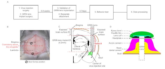
Figure 1: Schematic workflow and diagrams for stereotaxic surgery for in vivo microendoscopic calcium imaging in the L...
Toegang beperkt. Log in of start een proefperiode om deze inhoud te bekijken.
Materialen
| Naam | Bedrijf | Catalogusnummer | Opmerkingen |
|---|---|---|---|
| 26G needle | BD | 302002 | Surgery |
| AAV1-Syn-GCaMP7b-WPRE | Addgene | 104493-AAV1 | Surgery |
| AAV2/1-CaMKiiα-GFP | custom made | Surgery | |
| Acrylic-dental cement (Ortho-jet Acrylic Pink) | Lang | 1334-pink | Surgery & baseplate attachment |
| Air flow manipulator | Neurotar | NTR000253-04 | Baseplate attachment |
| Amoxicillin | SIGMA | A8523-5G | Surgery |
| Carbon cage | Neurotar | 180mm x 70mm | Baseplate attachment |
| Carprofen | SIGMA | PHR1452-1G | Surgery |
| Data processing software | INSCOPIX | INSCOPIX Data Processing Software | Baseplate attachment & behavior test |
| Dexamethasone | SIGMA | D1756-500MG | Surgery |
| Drill | Seyang | marathon-4 | Surgery |
| Drill bur | ELA | US1/2, Shank104 | Surgery |
| Glass needle | WPI | PG10165-4 | Surgery |
| GRIN lens (INSCOPIX Proview Lens Probe) | INSCOPIX | 1050-002208 | Surgery |
| Hamilton Syringe | Hamilton | 84875 | Surgery |
| Head plate | Neurotar | Model 5 | Surgery |
| Laptop computer | Samsung | NT950XBV | Surgery |
| Lens holder, Stereotaxic rod (INSCOPIX proview implant kit) | INSCOPIX | 1050-004223 | Surgery |
| Microscope gripper | INSCOPIX | 1050-002199 | Baseplate attachment |
| Microscope, DAQ software, hardware | INSCOPIX | nVista 3.0 | Baseplate attachment & behavior test |
| Mobile homecage | Neurotar | MHC V5 | Baseplate attachment |
| Moterized arm | Neurostar | Customized | Surgery |
| Moterized arm software | Neurostar | Customized | Surgery |
| Removable epoxy bond | WPI | Kwik-Cast | Surgery |
| Resin cement (Super-bond) | Sun medical | Super bond C&B | Surgery |
| Skull screw | Stoelting | 51457 | Surgery |
| Stereotaxic frame | Stoelting | 51600 | Surgery |
| Stereotaxic manipulator | Stoelting | 51600 | Baseplate attachment |
