The process of electrospinning polymers for tissue engineering and cell culture is addressed in this article. Specifically, the electrospinning of photoreactive macromers with additional processing capabilities of photopatterning and multi-polymer electrospinning is described.
A subscription to JoVE is required to view this content. Sign in or start your free trial.
Method Article
Electrospinning Fibrous Polymer Scaffolds for Tissue Engineering and Cell Culture
In This Article
Summary
Abstract
As the field of tissue engineering evolves, there is a tremendous demand to produce more suitable materials and processing techniques in order to address the requirements (e.g., mechanics and vascularity) of more intricate organs and tissues. Electrospinning is a popular technique to create fibrous scaffolds that mimic the architecture and size scale of the native extracellular matrix. These fibrous scaffolds are also useful as cell culture substrates since the fibers can be used to direct cellular behavior, including stem cell differentiation (see extensive reviews by Mauck et al. and Sill et al. for more information). In this article, we describe the general process of electrospinning polymers and as an example, electrospin a reactive hyaluronic acid capable of crosslinking with light exposure (see Ifkovits et al. for a review on photocrosslinkable materials). We also introduce further processing capabilities such as photopatterning and multi-polymer scaffold formation. Photopatterning can be used to create scaffolds with channels and multi-scale porosity to increase cellular infiltration and tissue distribution. Multi-polymer scaffolds are useful to better tune the properties (mechanics and degradation) of a scaffold, including tailored porosity for cellular infiltration. Furthermore, these techniques can be extended to include a wide array of polymers and reactive macromers to create complex scaffolds that provide the cues necessary for the development of successful tissue engineered constructs.
Protocol
A. Single Polymer Electrospinning
- Prior to preparing the electrospinning solution, make a 0.5 wt% solution of the photoinitiator, Irgacure 2959 (I2959), in deionized water by dissolving at 37°C for several days. This step is not necessary if a photoreactive polymer is not being used.
- Combine methacrylated hyaluronic acid (MeHA, see Burdick et al. for synthesis), poly(ethylene oxide) (PEO, 900 kDa), and I2959 in deionized water to prepare a solution with a final concentration of 2 wt% MeHA, 3 wt% PEO, and 0.05 wt% I2959. Use a vortex to mix the solution until it is clear. The polymer type and concentration, as well as the solvent used can be modified at this step depending on the desired scaffold properties.
- Transfer the solution into a syringe and attach an 18 gauge, 6 inch long, blunt end needle to the end.
- Program a syringe pump to eject at a rate of 1.2 mL/hr. Insert the syringe and needle into the device.
- Attach the grounded lead of a high voltage power source to the collection apparatus. To collect randomly distributed fibers use a flat metal plate, or use a mandrel rotating at ~10 m/s to collect aligned fibers. Attach the positively charged lead to the needle. See Figure 1 for a schematic of the electrospinning apparatus.
- Adjust the needle or collecting device, such that there is a 15 cm distance between the two.
- Start the flow on the syringe pump. When fluid is visualized on the tip of the needle, turn on the power source and set the voltage to 22 kV.
- After the collection is complete (from several minutes for thin films, to up to 24 hours for a thicker mat), remove the scaffold from the collection apparatus and store it under vacuum overnight to ensure complete removal of the solvent.
- Visualize the fiber morphology using scanning electron microscopy (SEM), a representative scaffold is shown in Figure 1 for both aligned and non-aligned structures.
Note: The sample flow rate, distance to collection device, and voltage are dependent on the polymer and solvent combination and must be optimized for each system, usually by observing the scaffold morphology with SEM.
B. Photocrosslinking and Photopatterning
- Cut out 5mm X 5mm samples from the scaffold mat.
- Prepare for crosslinking by placing each scaffold on a foil covered glass slide, placing the photomask directly on the scaffold, covering with a clean glass slide and clipping both ends with binder clips. Note: four samples can be done at once, and a transparency without a pattern can be used for crosslinking if a pattern is not desired.
- Purge scaffold set up in a nitrogen chamber. It is important to keep the construct free from oxygen, which can inhibit crosslinking.
- Place scaffold setup in nitrogen chamber under ~10 mW/cm2 365 nm light with a collimating adapter for 5 minutes. See schematic in Figure 2.
- Remove each scaffold and place in a 12 well plate.
- Add 2 mL of deionized water into each well, parafilm the plate to prevent evaporation of the water and place at 37°C for 24 hours. Change the water three times.
- Visualize pore formation under light microscope (see example in Figure 2). The scaffolds are now ready for use.
Note: Photocrosslinking is not necessary for many types of polymers, however photopatterning can only be used with photoreactive polymers.
C. Dual Polymer Electrospinning with Fluorescent Fiber Visualization
- Prepare a 5 wt% solution of PEO (200 kDa) in 90% ethanol. Stir at 700 rpm at 50°C for at least 2 hours prior to electrospinning.
- Transfer the PEO solution to a syringe and add DAPI for a final concentration of 10 mg/mL concentration in the electrospinning solution. Wrap the syringe in aluminum foil to protect it from light.
- Prepare the same solution described in step A2, except also add methacryloxyethyl thiocarbamoyl rhodamine B (MeRho, 683.24 g/mol) for a final concentration of 25 μM in the electrospinning solution. Wrap the syringe in aluminum foil to protect it from light.
- Carefully use scotch tape to secure methacrylated glass coverslips (see Khademhosseini et al.) to the surface of the mandrel. Note: fibers will become tethered to methacrylated glass coverslips.
- Attach one end of a 5 mm long piece of silicone tubing with luer lock attachments to one of the syringes and attach the other end to a needle. Insert the syringe into the syringe pump and put the needle through the hole in the fanner. Repeat with the other syringe and fanner on the opposite site of the mandrel. The fanners translate the length of the mandrel and are used to ensure an equal distribution of both polymers in the resulting scaffold. See schematic in Figure 3.
- Adjust the parameters described in Section A appropriately according to Table 1. Ensure that the needle tips are centered on the mandrel.
Table 1. Dual Polymer Electrospinning Parameters
Syringe Fanner to Needle Tip (cm) Needle Tip to Mandrel (cm) Flow Rate (mL/hr) Applied Voltage (kV) MeHA 6 15 1.2 +22 PEO 6 10 1.2 +15
- Once everything is aligned properly, turn off the lights and turn on the mandrel and the syringe pumps. Remove the aluminum foil from the syringes. When fluid is visible on the tips of both needles, simultaneously turn on the power supplies and plug in the fanners.
- When collection is complete, turn off the power supplies and mandrel and unplug the fanners. Carefully remove the coverslips and tape using a razor blade.
- Visualize the fibers using a fluorescent microscope equipped with filters for rhodamine and DAPI. See example in Figure 3. Note: Fluorescent fibers are most clear to view when electrospun for short periods of time (<3 minutes), however, this process can be extended for an unlimited amount of time in order to create thicker constructs, especially without the use of the glass coverslips.
D. Seeding Cells on Scaffolds
- Place each coverslip with electrospun polymer attached into an individual well of an appropriately sized well plate. Note: cellular interactions with the fibers are easily visible by electrospinning onto methacrylated glass coverslips. Also, MeRho can again be used for fiber visualization.
- Incubate the scaffolds in PBS overnight to ensure complete removal of solvent and any possible leachable by-products.
- Remove the PBS from the wells.
- To sterilize the scaffolds, place them under a germicidal lamp in a laminar flow hood for 30 minutes. If a full scaffold is being seeded, flip the scaffold over and place under a germicidal lamp for another 30 minutes.
- Perform standard cell culture and prepare a concentrated cell suspension at the desired cell density (e.g., 6,000 cells cm-2). For example, use a 100 mL of cell suspension for a 22 mm X 22 mm coverslip. Place in the incubator for 1 hour.
- Add the appropriate amount of cell culture media to each well. Place the scaffolds back into the incubator.
- Stain the cells using a commercially available Live/Dead kit. Note: other types of cell staining, such as DAPI (cell nuclei) and fluorescently labeled phalloidin (actin stress fibers) can be applied to visualize the cells.
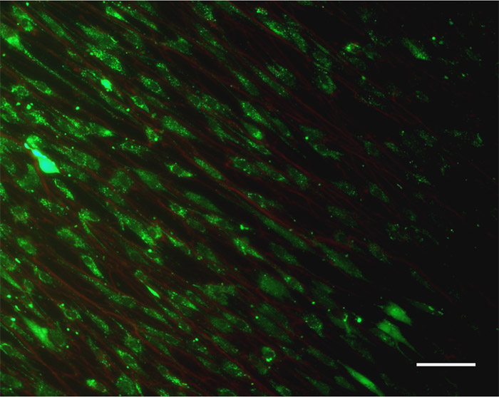
- Visualize the cells and fibers using a fluorescent microscope equipped with filters for TRITC and FITC. See example in Figure 4.
Representative Results:

Figure 1. Schematic illustrating the device setup for non-aligned scaffold formation (top) and aligned scaffold formation (bottom). Example scanning electron microscopy images of each type of scaffold are shown. Scale bar = 5μm. Please click here to see a larger version of figure 1.
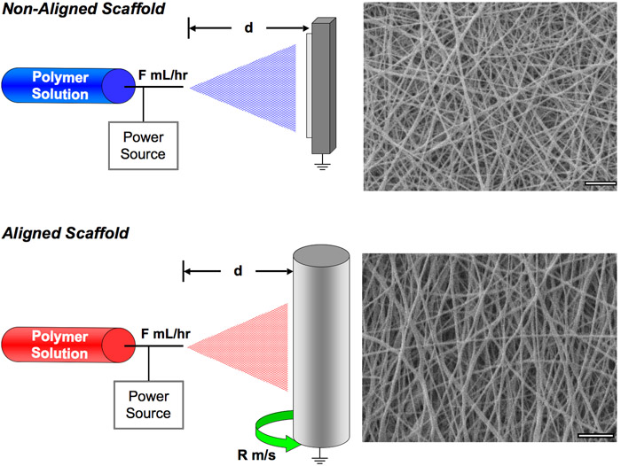

Figure 2. Schematic of patterning method. Patterns are formed by placing a photomask between the light source and scaffold during photocrosslinking and then washing away unreacted polymer. Photomask and SEM image of scaffolds after pore formation and lyophilization. Scale bar = 100 μm. Please click here to see a larger version of figure 2.
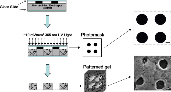

Figure 3. Schematic of the multi-polymer electrospinning setup and necessary processing parameters, as well as a representative fluorescent image of a mixture of two fiber populations (example: red MeHA and blue PEO) which were simultaneously electrospun to form a multi-polymer scaffold. Scale bar = 100 μm. Please click here to see a larger version of figure 3.
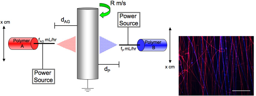

Figure 4. An example Live/Dead staining image of human mesenchymal stem cells and their interactions with the electrospun fibers. Scale bar = 100 μm. Please click here to see a larger version of figure 4.
Access restricted. Please log in or start a trial to view this content.
Discussion
Electrospinning was used to prepare fibrous scaffolds from polymers. Photocrosslinkable scaffolds based on hyaluronic acid were used as an illustrative example, where light exposure is needed for crosslinking. With the use of reactive macromers, such as MeHA, channels that have previously demonstrated enhanced cellular distribution were incorporated into the scaffolds with the use of a mask during photocrosslinking to form macro and micro-porous scaffolds. Moreover, two distinct polymers were simultaneously electrospu...
Access restricted. Please log in or start a trial to view this content.
Acknowledgements
This work was supported by an American Heart Association Predoctoral Fellowship to JLI and National Institutes of Heath grant R01AR056624.
Access restricted. Please log in or start a trial to view this content.
Materials
| Name | Company | Catalog Number | Comments | |
|---|---|---|---|---|
| DAPI | Reagent | Invitrogen | D1306 | |
| I2959 | Reagent | Ciba Specialty Chemicals | ||
| PEO 200 kDa | Polysciences, Inc. | 17503 | ||
| PEO 900 kDa | Reagent | Sigma-Aldrich | 189456 | |
| Methacryloxethyl thiocarbamoyl rhodamine B | Reagent | Polysciences, Inc. | 23591-100 | Prepare stock solution in DMSO |
| Live/Dead Stain Kit | Reagent | Invitrogen | L3224 | Contains Calcein (stains live cells green) and ethidium homodime (stains red dead cells) |
| Syringe Pump | Equipment | KD Scientific | KDS100 | Two are needed for dual polymer spinning |
| Power Source | Equipment | Gamma High Voltage | ES30P-5W | Two are needed for dual polymer spinning |
| Motor | Equipment | Triem Electric Motors, Inc | 0132022-15 | Must attach to a custom built mandrel |
| Tachometer | Equipment | Network Tool Warehouse | ESI-330 | Use to monitor mandrel speed |
| Omnicure UV Spot Cure System with collimating adapter | Equipment | EXFO | S1000 | |
| Silicone Tubing | Equipment | McMaster-Carr | 51135K151 | |
| Luer Lock Female Adapter | Equipment | McMaster-Carr | 51525K293 | |
| Luer Lock Male Adapter | Equipment | McMaster-Carr | 51525K143 | |
| Needles | Equipment | Fisher Scientific | 14-825-16H | |
| Coverslips | Equipment | Corning | 2875-22 |
References
- Burdick, J. A., Chung, C., Jia, X., Randolf, M. A., Langer, R. Controlled degradation and mechanical behavior of photopolymerized hyaluronic acid networks. Biomacromolecules. 6, 386-391 (2005).
- Baker, B. M., Gee, A. O., Metter, R. B., Nathan, A. S., Marklein, R. A., Burdick, J. A., Mauck, L. R. The potential to improve cell infiltration in composite fiber-aligned electrospun scaffolds by the selective removal of sacrificial fibers. Biomaterials. 29, 2348-2358 (2008).
- Ifkovits, J. L., Burdick, J. A. Review: Photopolymerizable and degradable biomaterials for tissue engineering applications. Tissue Engineering. 13, 2369-2385 (2007).
- Khademhosseini, A., Eng, G., Yeh, J., Fukuda, J., Blumling, J., Langer, R., Burdick, J. A. Micromolding of photocrosslinkable hyaluronic acid for cell encapsulation and entrapment. J. Biomed Mater Res A. 79A, 522-532 (2006).
- Mauck, R. L., Baker, B. M., Nerurkar, N. L., Burdick, J. A., Li, W. J., Tuan, R. S., Elliott, D. M., M, D. Engineering on the Straight and Narrow: The Mechanics of Nanofibrous Assemblies for Fiber-Reinforced Tissue Regeneration. Tissue Engineering B. 15, 171-193 (2009).
- Sill, T. J., Von Recum, H. avon Electrospinning: applications in drug delivery and tissue engineering. Biomaterials. 29, 1989-2006 (2008).
- Sundararaghavan, H. G., Metter, R. B., Burdick, J. A. Electrospun fibrous scaffolds with multi-scale and photopatterned porosity. , Forthcoming (2009).
Access restricted. Please log in or start a trial to view this content.
Reprints and Permissions
