Method Article

Aptamer-Assisted Acoustophoresis for Microfluidic Separation of Gram-Negative Bacteria

August 29th, 2025

In This Article

Abstract

Loading...
$$\rightleftharpoonup{xx}$$ $$\longleftharp{xx}$$, $$\longrightharp{xx}$$,

Source: Choi, H. J., et al. Microfluidic Acoustophoresis for Flowthrough Separation of Gram-Negative Bacteria using Aptamer Affinity Beads. J. Vis. Exp. (2022)

This video demonstrates the method of selectively separating Gram-negative bacteria from a mixed bacterial sample using aptamer-coated microbeads and acoustic forces within a microfluidic chip.

Protocol

Loading...
$$\rightleftharpoonup{xx}$$ $$\longleftharp{xx}$$, $$\longrightharp{xx}$$,
  1. Acoustophoresis setup and operation
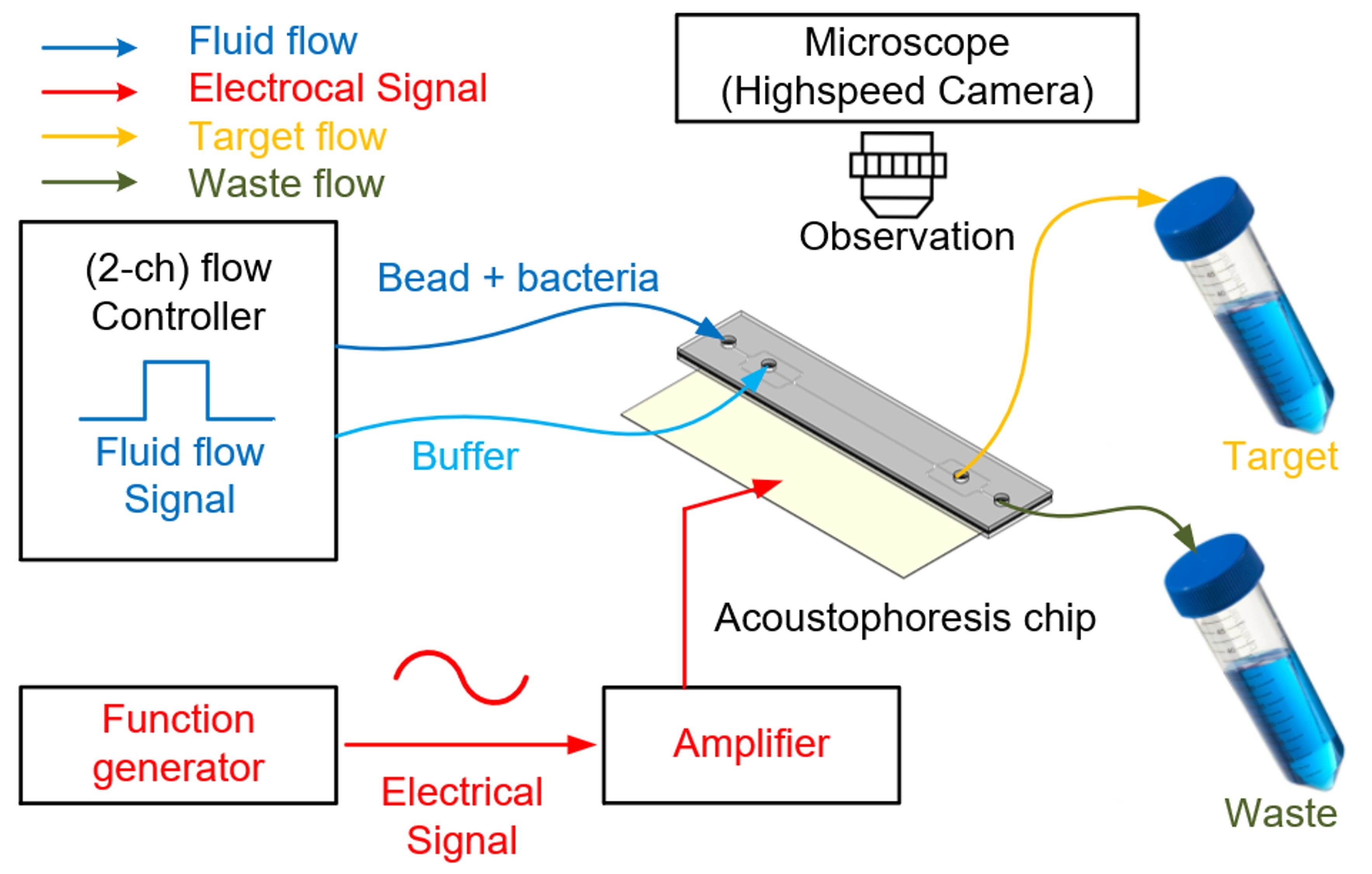
    1. Connect polyetheretherketone (PEEK) tubes to the two inlets for injecting two samples and buffer, and the two outlets for collecting and discharging waste (Figure 1).
    2. Manually fill the microfluidic acoustophoresis channel with bubble-free demineralized water using a 10 mL syringe.
    3. Prepare a precision pressure controller with two or more output channels to control the fluid flow. Then, half-fill the vials with sample and buffer, respectively, with two holes in their caps, and connect them to the chip inlet.
      NOTE: A precision pressure controller with two or more output channels can be replaced with multiple precision pressure controllers. At the buffer inlet, a buffer capable of generating a laminar flow that prevents the sample from moving to the center during sample injection is injected through a flow controller.
    4. After preparing the device, inject the sample and buffer by applying a pressure of 2 kPa to the sample inlet and 4 kPa to the buffer inlet using the precision pressure control device.
      NOTE: At this time, for smooth laminar flow, the injection pressure of the buffer should be higher than the injection pressure of the sample. The flow is controlled by a flow controller fixed to the aspirator connected to the inlet channel.
    5. Focus on a bead using the piezoelectric transducer (PZT) to move it into the center of the microfluidic channel while checking through the microscope.
      NOTE: The larger the bead, the greater the effect on the waveform, so it is easier to align with the node point. A function generator with an amplifier applies power to the PZT to generate a sine wave in the microchannel. Since the upper and lower portions of the microchannel are made of glass, the generated sine wave is reflected and creates a node point.
    6. Using a single-channel function generator, generate a resonance frequency of 3.66 MHz and amplify a typical signal by 16 dB (about nine-fold) using a power amplifier (Figure 1).
      NOTE: The actuator's resonance frequency must match the channel's size, because the channel is square, the PZT operates at an accurate frequency to create a single node.
    7. Observe the separation and enrichment processes on the acoustofluidic chip with a fluorescence microscope and a high-speed camera operating at 1,200 fps (frames per second).
    8. Quantify and analyze the presence or absence of Gram-negative (GN) bacteria and Gram-positive (GP) bacteria by checking the images taken with the fluorescence microscope camera of the bacteria-bound beads and bacteria discharged through the collection and waste outlet samples.
      NOTE: Microbeads with buffer, bacteria, and aptamers pass through the main channel, and the microbeads are aligned centrally via in-chip acoustophoresis induced by the PZT. Finally, microbeads that have bound GN bacteria are collected at the collection outlet, and the uncollected bacteria are discharged through the waste outlet.

Access restricted. Please log in or start a trial to view this content.

Results
Loading...
$$\rightleftharpoonup{xx}$$ $$\longleftharp{xx}$$, $$\longrightharp{xx}$$,
Acoustophoresis chip setup diagram; fluid flow control, electrical signal; high-speed observation.


Figure 1: Schematic of the acoustofluidic system used to separate and collect cells. The ...

Access restricted. Please log in or start a trial to view this content.

Materials

List of materials used in this article
NameCompanyCatalog NumberComments
10 µm Streptavidin-coated microbeadsBang LaboratoriesCP01007Aptamer affinity beads
AptamerIntegrated DNA TechnologiesGN3-6'RNA for bacteria conjugation
Escherichia coli DH5αKCTCKCTC2571Target bacteria
Functional generatorGW InstekAFG-2225Generate frequency
High-speed cameraPhotronFASTCAM MiniObservation of separation
KOVAX-SYRINGE 10 mL SyringeKoreavaccine22G-10MLFill the microfluidic acoustophoresis channel with bubble-free demineralized water.
MicroscopeOlympus Corp.IX-81Observation of separation
PEEK TubesSaint-Gobain Ppl Corp.AAD04103Inject or collect particles
Piezoelectric transducerFuji CeramicsC-213Generate specific wave in channel
Power amplifierAmplifier Research75A250AAmplify frequency
Pressure controller/μfluconAMEDAMED-μfluconControl of air pressure/flow controller

Reprints and Permissions

Request permission to reuse the text or figures of this JoVE article

Request Permission

Tags

Aptamer Coated MicrobeadsAcoustic Wave SeparationPiezoelectric TransducerMicrofluidic ChipFluorescence MicroscopyPressure Control SystemHigh Speed Imaging

Related Articles