$$\rightleftharpoonup{xx}$$
$$\longleftharp{xx}$$,
$$\longrightharp{xx}$$,
1. Bacterial strains and culture protocols
- Streak colonies of bacteria on agar plates supplemented with appropriate growth media. In this report, B. subtilis (strain 1A1135, Bacillus Genetic Stock Center) is cultured on ATGN (0.079 M KH2PO4 (Potassium dihydrogen phosphate), 0.015 M (NH4)2SO4 (Ammonium sulfate), 0.6 mM MgSO4·7H2O (Magnesium sulfate heptahydrate), 0.06 mM CaCl2·2H2O (Calcium chloride dihydrate), 0.0071 mM MnSO4·H2O (Manganese(II) sulfate monohydrate), 0.125 M FeSO4·7H2O (Ferrous sulfate heptahydrate), 28 mM glucose, pH: 7 ± 0.2, 15 g/L agar) agar plates supplemented with 100 µg/mL spectinomycin and E. coli (strain 25922, ATCC) on ATGN agar plates supplemented with 100 µg/mL ampicillin.
NOTE: Prior reports of hydrogel encapsulation and release with these materials used A. tumefaciens C58 cells - Pick desired colonies from ATGN agar plates and start overnight cultures. For E. coli and B. subtilis strains used here, culture at 37 °C while shaking at 215 rpm in ATGN liquid medium for 24 h. Store the cell cultures in 50% glycerol at -80 °C until future use.
- Pick colonies of both strains from glycerol stocks using sterile inoculation loops and incubate in ATGN liquid media for 24 h at 37 °C and 215 rpm.
2. Preparation of the material needed for hydrogel formation
- Photodegradable PEG-o-NB-diacrylate (Poly(ethylene glycol)-ortho-nitrobenzyl-diacrylate) synthesis
NOTE: The in-house synthesis of the PEG-o-NB-diacrylate has been well-described and previously reported. Alternatively, because the synthesis is routine, it can be outsourced from a chemical synthesis facility. - Crosslinking buffer
- Take the recipe for the selected medium for the bacterial strain and prepare the media with 2x nutrients. Add phosphate, e.g., NaH2PO4 (Sodium dihydrogen phosphate), to the medium to a final concentration of 100 mM. Then, adjust the pH value to 8 using 5 M NaOH (Sodium hydroxide) (aqueous).
- Sterilize the buffer solution and store it at -20 °C until further use.
NOTE: Leave out any transition metals present in the media, as these metals catalyze the oxidation of the thiols to disulfides.
- PEG-o-NB-diacrylate solution
- For each mg of the aliquot PEG-o-NB-diacrylate (3,400 Da molecular weight) powder, add 3.08 µL of ultrapure water to reach 49 mM concentration of PEG-o-NB-diacrylate (98 mM acrylate concentration).
- Vortex the solution until it is well mixed and store this solution at -20 °C until further use.
- 4-arm PEG-thiol solution
- For 4-arm PEG-thiol (10,000 Da molecular weight) preparation, add 4 µL of ultrapure water per mg powder to reach a 20 mM concentration (80 mM of thiol concentration).
- Vortex this solution until it is well-mixed and store this solution at -20 °C until further use.
3. Preparation of perfluoroalkylated (non-reactive) coverslips
- Place up to 5 glass slides (25 mm x 75 mm x 1 mm) inside a polypropylene slide mailer. Sonicate the slides with a 2% (w/v) detergent solution (Table of Materials) for 20 min.
- Rinse the slides three times with ultrapure water, then sonicate the slides in water for 20 min. Dry the slides using a stream of N2 (nitrogen).
- Plasma clean (see Table of Materials) on both sides of the glass slides according to the protocol in section 4.1 for 2 min.
- Place the plasma-cleaned slides back into the slide mailer and fill the container with a 0.5% (v/v) solution of trichloro(1H, 1H, 2H, 2H,-perfluorooctyl)silane in toluene. Allow these glass slides to be functionalized for 3 h at room temperature (RT).
- After the slides are functionalized, rinse the slides within the slide mailer, first with toluene and next ethanol (three times with each solvent). Next, dry each functionalized slide with a stream of N2.
4. Preparation of thiol-functionalized (base) coverslips
- Cleaning of the glass coverslips using a plasma cleaner
- Place 18 mm x 18 mm coverslips in a Petri dish. Then, place the Petri dish in a plasma cleaner chamber and switch on the power of the plasma cleaner.
- Turn the vacuum pump on to clear the air within the chamber until the pressure gauge reads 400 mTorr.
- Open the metering valve to let air into the chamber until the pressure gauge reaches a steady pressure (800-1000 mTorr). Then, select RF with "Hi" mode and expose the coverslips for 3 minutes.
- After 3 minutes, turn off the RF mode and vacuum pump.
- Take the Petri dish out of the chamber, flip the coverslips, place them back in the chamber to the plasma, and expose the other side of the glass coverslip.
- Repeat steps 4.1.2-4.1.4 to clean the untreated side of the glass coverslip with plasma.
- After completing the process, remove the Petri dish from the chamber and turn the plasma cleaner and vacuum pump off.
- Cleaning and hydroxylation of the coverslips with piranha solution
NOTE: Standard piranha cleaning protocols can be used to clean and hydroxylate glass slips. Piranha solution is a 30:70 (v/v) mixture of H2O2 (Hydrogen peroxide) and H2SO4 (Sulfuric acid). Alternate methods of cleaning glass coverslips may also be used.
CAUTION: Piranha solution is strongly corrosive and explosive with organic solvents and should be handled with extreme caution. Appropriate safety and containment measures should be implemented, such as use of proper personal protective equipment (lab coat, chemical resistant apron, safety glasses, face shield, acid resistant butyl gloves). All glassware and working surfaces in contact with piranha solution should be clean, dry, and free of organic residues prior to use. Piranha solution should never be stored in a partially closed or closed container.- Place a clean 100 mm x 50 mm glass dish on a hotplate magnetic stirrer with adjustable stir speed under a fume hood and add 14 mL of H2SO4 to the dish.
- Gently place a small, Teflon-coated magnetic stir bar using teflon-coated forceps inside the dish. Then, turn the stirrer slowly to avoid splashing the acid.
- Next, gently add 6 mL of H2O2 to the dish and allow the solution to become well-mixed.
- Turn off the stirrer, then remove the stir bar from the dish using the forceps. Next, gently place the coverslips inside the dish using the forceps and set the temperature to 60–80 °C.
- After 30 min, gently remove the coverslips using the forceps and submerge them in deionized water (DI) water two times to wash off residual piranha solution.
- After rinsing with water, store the coverslips in DI water at RT until further use.
- Turn off the hotplate and allow the piranha solution to cool.
- To dispose of the piranha solution, gently place the 100 mm x 50 mm glass dish containing the cooled piranha solution in a larger, empty glass beaker that is at least 1.5 L in volume. Then add 1 L of water to dilute and add sodium bicarbonate powder to neutralize. Note that sodium bicarbonate will cause bubbling and heat generation and should be added very slowly; otherwise, bubbling may lead to splashing of the acid. When further addition of sodium bicarbonate does not cause bubbling, check the pH with pH paper to verify that it has been neutralized. Once the solution is neutralized and cooled, it can be poured down the sink.
- Thiol functionalization of the coverslips
- Prepare a 5% (v/v) solution of 269 mM of (3-mercaptopropyl) trimethoxysilane (MPTS) solution in dry toluene.
- Add 10 mL of the solution to individual 50 mL conical centrifuge tubes. Place one cleaned coverslip in each tube and submerge it in the solution.
NOTE: One coverslip per 50 mL tube is used to assure the thiolation of both sides of the substrate without being disturbed by other substrates. - After 4 h, wash each coverslip (four washes per coverslip) with toluene, a 1:1 (v/v) ethanol: toluene mixture, and ethanol.
NOTE: This is done by immersing each coverslip sequentially into conical centrifuge tubes containing the mentioned solutions. - After rinsing the substrate, submerge it in ethanol and store it at 4 °C until further use.
NOTE: Depending on the number of coverslips, this method can become laborious due to treating coverslips one at a time. For multiple coverslips, Columbia jars that fit several coverslips at the same time can be used.
5. Fabrication of silicon microwell arrays
- Parylene coating: Use the standard protocol described in previous research articles to coat silicon wafers with parylene.
- Microfabrication: Follow the protocol described by Barua et al. to design and fabricate the microwell array.​
6. Hydrogel formation
- Bulk hydrogel formation on glass coverslips
- Hydrogel precursor solution: Add 12.5 µL of the crosslinking buffer to a 0.5 mL microcentrifuge tube, followed by 5.6 µL of PEG-o-NB-diacrylate solution. Lastly, add 6.9 µL of 4-arm PEG-thiol solution to the mixture.
NOTE: Adding the 4-arm PEG thiol to the mixture initiates the crosslinking reaction. Thus, the hydrogel precursor solution should be used immediately after mixing. - For cell encapsulation in the hydrogel precursor solution, follow steps 6.1.3-6.1.9.
- For cell encapsulation, before step 6.1.1, inoculate the crosslinking buffer with the desired cell density. As reported previously19, it was observed that cell density of 7.26 × 10⁷ CFU/mL in the crosslinking buffer correlates to a density of ~ 90 cells/mm2 encapsulated across the hydrogel.
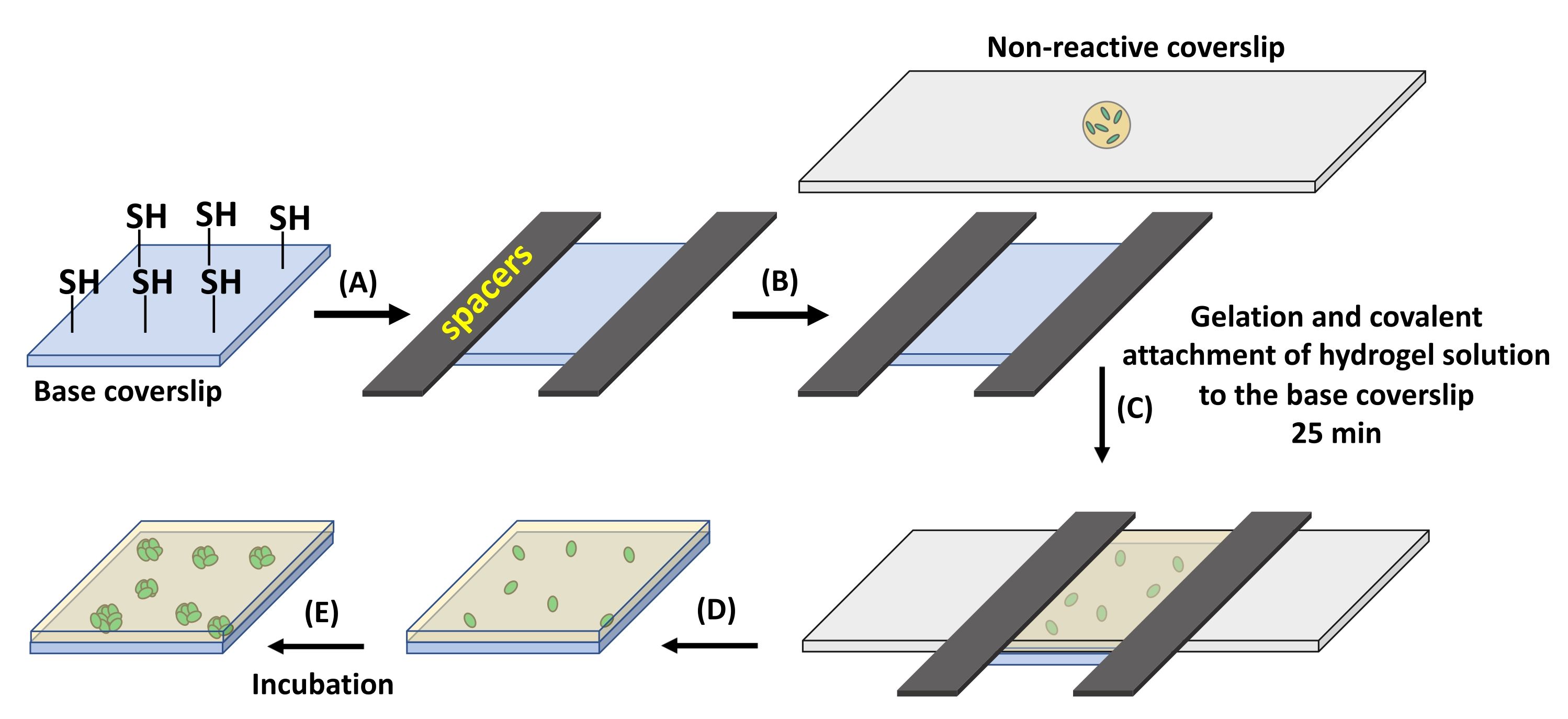
- Place the thiolated base coverslip on a clean Petri dish. Place two spacers (see Table of Materials) on the two opposing sides of the coverslip.
NOTE: Thiol functionalization of the coverslips is necessary for the covalent attachment of the hydrogel to the coverslip surface. This is done through the reaction of thiol groups on the surface and the acrylate groups present in the hydrogel precursor solution. - Fix the spacers on the base coverslip by taping the spacers to the Petri dish.
- Pipette the desired volume of the precursor solution on a non-reactive, perfluoroalkylated glass slide.
- Place the perfluoroalkylated glass slide on the base coverslip (Figure 1C). Wait for 25 min at RT for hydrogel formation to complete.
- After gelation, gently remove the perfluoroalkylated glass slide. The hydrogel will stay attached to the base coverslip.​
NOTE: For 18 mm x 8 mm coverslips to obtain a 12.7 µm thick membrane, use ~7 µL of the precursor solution (Figure 1A, B). Using higher volumes of precursor solution may result in a hydrogel underneath the base coverslip. This may cause the base coverslip to stick to the Petri dish and break upon an attempt at removal. Also, hydrogel residue underneath the coverslip is problematic for microscopy. Gentle removal of the non-reactive perfluoroalkylated glass slide is required, as fast removal can damage the hydrogel. - Place the substrate in a 60 mm x 15 mm Petri dish in the specified culture media. Here, ATGN media supplemented with 100 µg/mL spectinomycin for B. subtilis or 100 µg/mL ampicillin for E.coli at 37 °C was used for 24 h culture times.
7. Material preparation for cell extraction
- PDMS (Polydimethylsiloxane) holder preparation
- Tape a stack of ten 18 x 18 mm coverslips together and glue this stack of coverslips to the bottom of a Petri dish.
- To fabricate PDMS holders, mix PDMS precursor and curing agent at a 10:1 volume ratio in a plastic cup, degas the mixture in a vacuum desiccator, and then pour the mixture into the Petri dish.
- Cure PDMS for 90 min at 80 °C. Then, cut around the taped block to remove the PDMS holder and place the PDMS holder on a glass slide for easier handling for microscopy.
- Microsyringe and tubing preparation
- Cut 20 cm of PTFE (Polytetrafluoroethylene) tubing (0.05 in I.D.) and attach one end of the tubing to a 100 µL microliter syringe.
NOTE: For extraction, avoid using pipettes as drawing the released cells via a pipette tip can damage the hydrogel surface and lead to contamination.
8. Hydrogel degradation with the patterned illumination tool
- Turn on the microscope (see Table of Materials). Then, turn on the patterned illumination tool (see Table of Materials).
- Turn on the 365 nm LED light source Analog and Digital control module. Next, turn on the LED light source control module.
- Open the microscope software and the software for the patterned illumination tool. When the hardware configuration window is opened, select the Load button.
NOTE: Three devices will be loaded here. (Third-party camera, a control module, and the patterned illumination tool) - Press the Start button. The light patterning software window will now open. Select the first option, the Device Control button, on the left sidebar of the window.
- Calibrate the patterned illumination tool.
NOTE: Calibration must be done with the same microscope objective and filter that will be used for light exposure.- Set the microscope objective to 10x magnification.
NOTE: This magnification allows enough working distance between the microscope lens and the sample surface. It also allows for monitoring and recording the retrieval process in real time through the image window. - Set the microscope lens and filter to the settings used for light exposure and place the calibration mirror under the microscope.
- In the Device Control window, press the LED Control tab. Turn on LED #1 and set the light intensity to the desired number. In standard extraction experiments, this is set to 60%.
- Press the tab titled with the patterned illumination tool product name in the Device Control window. Then, press the Show Grid button.
NOTE: A grid pattern will be projected on the calibration mirror. - Adjust the microscope focus and camera exposure to obtain high image quality of the grid and rotate the camera to align the grid lines parallel to the camera window frame, if needed.
- Select the Calibration Wizard button under the tab titled with the patterned illumination tool product name, and follow the instructions provided by the software in this window.NOTE: A third-party camera setup window will be opened.
- A calibration Type Selection window will be opened. Select Automatic Calibration and press Next.
- When the Pre-calibration Adjustment window opens, follow the software instructions and press the Next button.
- When the Mapping Information window opens, save this calibration accordingly in the desired folder. This is done by putting in the date, microscope name, objective lens, and filter.
- After calibration, press the Working Area Definition button found under the tab titled with the patterned illumination tool product name to define the working area of the patterned illumination tool if needed.
- Sequence Design section for pattern preparation.
- Press the Sequence Design button on the left sidebar of the software window. Then, press the Profile Sequence Editor button.
- When the Profile Sequence Editor window opens, select the New Profile option under the Profile List.
NOTE: Now, a Pattern Editor window will be opened. - Prepare the desired pattern for light exposure by choosing different pattern shapes and sizes or manually drawing the pattern, if desired.
- For circle and broken cross patterns for the bulk hydrogel, follow steps 8.6.5- 8.6.6
- For circle patterns, define a circle with a 30 µm diameter over a target bacterial colony to cover the whole colony. Choose the shape fill color white.
- For broken cross patterns, choose the rectangle shape from the pattern drawing window with 3 µm x 8 µm dimensions. Place four rectangles with these dimensions on the edges of the target colony, while half the patterns have an overlay with the colony.
- For circle and ring patterns for the microwell arrays, follow steps 8.6.8-8.6.10.
- For circle patterns, draw a 10 µm diameter circle around the well perimeter. Choose the shape fill color white.
- For the ring pattern, draw a circle of diameter 20 µm, place it over the well and choose the shape fill color white.
- Draw another circle pattern of diameter 10 µm with fill shape color black and place it around the perimeter of the well.
- Edit the pattern and modify the shapes based on the desired extraction method. Ensure that the desired pattern exists within the working area of the patterned illumination tool.
- Place the sample in a PDMS holder and pipette the defined media on top of the sample to prevent sample dehydration and provide a carrier solution for released cells.
- Then, replace this with the calibration mirror.
- Adjust the microscope focus to get a sharp image of the colonies within the hydrogel. Inspect the colonies to identify a colony of interest.
- Here, design the light patterns while the camera view shows the colonies inside the sample to test different patterns for cell extraction.
- Save the defined pattern. After saving the defined pattern, select the Session Control section.
- In this section, under the tab titled with the patterned illumination tool product name, add the saved sequence.
- After adding the sequence, choose the option to simulate the pattern to view and adjust for the desired location of exposure.
NOTE: The sample location can be adjusted here to ensure the pattern is precisely projected in the targeted area. - Next, adjust the light intensity to 60% and the exposure time to 40 s under the LED control tab and start the exposure process.
- Monitor the hydrogel degradation in real-time and brightfield mode to ensure cell release.
NOTE: Prevent any movements to the sample during light exposure as it can cause degradation of unwanted areas of the hydrogel resulting in cross-contamination.
9. Cell retrieval
- After 365 nm light exposure and cell release, the cells are collected using a microliter syringe and microfluidic tubing (Figure 2).
NOTE: Cell retrieval needs to be done immediately after pattern exposure. This allows for localized cell recovery before the released cells move away from the irradiated area. - Change the microscope from brightfield to FITC or TRITC filter to allow for visualizing the exposed area of the sample by the naked eye.
- Once the exposed area is located, place the end of the tubing upon the irradiated spot. Then, change the microscope filter back to brightfield to monitor cell retrieval in real-time.
- Use the syringe attached to the other end of the tubing to carefully withdraw the released cells. Withdraw 200 µL of the solution and insert the solution into a 1.5 mL centrifuge tube for DNA analysis or plating.