1. PDMS Device Casting
- In a dust-free environment, mix Polydimethylsiloxane (PDMS) polymer and curing agent at a 10:1 ratio and degas under vacuum for at least 10 min.
- Place a silicon master (or an epoxy or polyurethane replica thereof) on a piece of unbroken aluminum foil in a polystyrene Petri plate. Pour the degassed PDMS mixture over the master to a depth of approximately 5 mm. Degas the Petri plate for at least 10 min. Use a gentle stream of air to break surface bubbles.
NOTE: A plastic replica master may partially float during degassing; if this occurs, push down the replica with a clean plastic applicator. - Cure PDMS for at least 1 h in an oven at 60 °C and cool to room temperature. Remove the aluminum foil containing the master and cured PDMS from the Petri plate. Carefully peel off the aluminum foil from the back of the master, then carefully peel the PDMS from the master.
NOTE: Alternatively, PDMS may be cured overnight at room temperature. The relative fragility of a silicon-wafer master may be overcome by using epoxy adhesive to permanently bond the wafer to a 1/16 inch-thick aluminum disc of the same size as the wafer. - As a wafer typically includes several microfluidic devices with slightly different dimensions, cut a single device to size using a clean, sharp scalpel.
NOTE: For routine Bacillus subtilis work, use devices with 1.0-µm-wide cell trenches.
2. Device Punching and Bonding
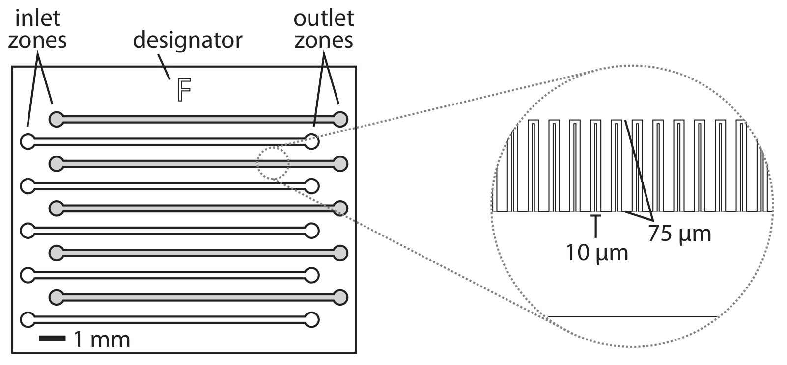
- Place a piece of translucent office tape (see Table of Materials) over the patterned side of the device to enhance the visibility of the patterned features. The inlet and outlet ports are identified as circular areas at opposite ends of the visible fluidic channels (Figure 1). To improve their visibility when punching holes in the device for the inlet and outlet pins, mark the inlets and outlets with dots using a fine-tipped marker.
NOTE: To ensure that the inlet and outlet pins are not crowded, every other channel is punched, beginning with the channel just beneath the alphabetical designator for the device. - Flip the PDMS device so that the patterned side is down, and punch through the device to the marked dots using a 0.75-mm biopsy punch; discard the punchings.
NOTE: The devices are punched with the patterned side down because the hole generated by the biopsy punch is typically slightly flared where the punch enters the polymer. Punching the device in an inverted orientation ensures that the hole on the patterned side has a sharp border. - Using a stereomicroscope, ensure that the punched holes overlap with the inlet and outlet areas of the device. Use fine-tipped tweezers to remove any extraneous fragments of PDMS from the punched holes.
- Use adhesive tape to remove dust from both sides of the device and place it into a clean polystyrene Petri plate. Prepare a 22 mm x 40 mm cover glass by wetting with 100% isopropyl alcohol and rubbing with a cleanroom wipe; dry with a stream of dust-free air or nitrogen.
- Place the punched PDMS device feature side up together with the cleaned cover glass into an oxygen plasma cleaner.
- Plasma-treat the device with the following settings: vacuum, 70 mTorr; O₂ pressure, 200 mTorr; duration, 15 s; power, 30 W. Immediately after the plasma treatment period finishes, remove the device and cover glass from the plasma cleaner.
- Invert the PDMS and place it on the center of the cover glass so that the patterned side contacts the glass; ensure that the feeding channels (running between the inlet and outlet areas) are aligned with the long axis of the cover glass. Press down very gently to ensure that the PDMS seals against the glass.
- Bake the assembled device in an oven for at least 1 h at 60 °C. After baking, manually verify that the PDMS is bonded to the glass by pushing gently on one corner of the device.
NOTE: Once the device is bonded, it should be used within 24 h, as the polymer will become increasingly hydrophobic with increasing time after plasma treatment.
3. Microfluidic Plumbing Preparation
- Cut lengths of polymer tubing (inner diameter (ID) 0.02 inch, outer diameter (OD) 0.06 inch) to appropriate lengths to reach from the syringe pump to the switching apparatus (if used) and the device when mounted on the microscope. Cut as many lengths as there are microfluidic lanes.
- Assemble Y junctions for pinch valves (if using) by cutting and attaching 2-cm lengths of flexible silicone tubing (0.03 inch ID, 0.065 inch OD) to the top barbs of the "Y" and 1-cm lengths of silicone tubing to the bottom barb of the "Y."
- Cut 10-cm (or appropriate) lengths of polymer tubing; connect them at one end to the switch junction by inserting them into the 1-cm silicone tubing segments on the bottom barb of the "Y." Connect them at the other end to 21G needles that have been removed from their plastic syringe adaptors and bent approximately 90° approximately 9 mm from the needle end.
- Connect 21G blunt needles to one end of the tubing segments that will run from the syringes to the switch apparatus by inserting the needles into the tubing. Insert the other ends of each length of tubing into the silicone tubing segments on the inlet barbs of the Y junctions.
NOTE: Use some sort of apparatus to hold the pinch valves and junctions in place; this can easily be made from a micropipette tip box (Figure 2D). - Cut lengths of polymer tubing to carry waste from the outlet of the device to a waste beaker. Connect them at one end to bent 21-G needles prepared as described above. Tape the other end of the tubes into a waste beaker.
- Prepare appropriate volumes of media containing 0.1 mg/mL bovine serum albumin (BSA) and fill the desired size and number of syringes. Connect the BSA-loaded syringes to the prepared 21G needles attached to the inlet tubing and load syringes into syringe pumps.
NOTE: For typical experiments, 5 channels of the device are used, each with a 20-mL syringe. An experiment in which the medium is switched will require 2 banks of 5 syringes each. Here, the pump containing the first bank is referred to as the phase-1 pump, and the pump containing the second bank, with the post-switch medium, is referred to as the phase-2 pump. - Purge air from the inlet plumbing by running the syringe pumps at a high flow rate (>500 µL/min), beginning by orienting the syringe pumps vertically and tapping the syringes to bring air bubbles to the top. Once air has been purged from the syringes, place the syringe pump horizontally and progressively tap or flick the polymer lines from the syringes up through the switch apparatus to dislodge and purge air bubbles. Repeat this process for the second bank of syringes (if switching media).
- After air bubbles are purged, set the phase-2 syringe pump (i.e., with the medium that will be used second, after the switch) to 1.5 µL/min, then pause the flow. Place small binder clips onto the segments of flexible tubing on the branch of the Y junctions corresponding to the second medium phase. Continue to run the phase-1 syringe pump at a modest flow rate (e.g., 10 µL/min) for at least 30 min to purge the second medium from the inlet tubing downstream of the Y junction.
4. Cell Culture Preparation
- Grow a preculture of the strain of interest in the desired medium overnight, to the stationary phase. The bacterial strain should contain a mutation that renders the cells immobile, so that the cells do not swim out of the channels of the device.
NOTE: In this protocol, the bacterial strain is B. subtilis 3610 containing a hagA233V substitution (this mutation causes the flagellum to be straight rather than helical, preventing cell motility), a PrsbV-mNeonGreen reporter for cell stress, and a constitutive Phyperspank-mNeptune (red) reporter to highlight cells. Luria-Bertani (LB) Lennox medium is used in the example protocol. Typical strains for microfluidics experiments contain one or more fluorescent transcriptional reporters and a constitutively produced, cytoplasmic fluorescent protein to facilitate automated detection of cells. Growth defects were not observed when LB Lennox rich medium was used, but B. subtilis growth in minimal media may be inhibited under microfluidic conditions because secreted siderophores are washed away by the medium flow. Under such circumstances, growth may be restored by the addition of sodium citrate and ferric chloride to the medium, as reported for S750 medium. - The morning of the experiment, dilute the B. subtilis cells 1:50 into a baffled 250-mL flask containing 25 mL of growth medium. Grow the cells for 5 - 6 h in shaking culture at 37 °C to an optical density of greater than 1.
NOTE: A dense cell culture is preferable because the stationary-phase B. subtilis cells are smaller and less often found in cell chains, facilitating device loading. Different bacterial species may require other media or growth conditions for optimal loading. - Using a syringe fitted with a 5-µm pore-size filter, filter approximately 15 mL of cell culture into a 15-mL conical tube to remove B. subtilis cell chains (it is unnecessary for E. coli and may not be necessary with other species).
NOTE: Relatively few cells should be removed; the filtrate should be turbid. - Centrifuge the filtered culture for 10 min at 4,000 x g at room temperature. Pour off the supernatant and resuspend the cell pellet in the residual supernatant fluid remaining in the tube, adding approximately 500 µL of fresh medium if necessary to facilitate pipetting the cell suspension.
5. Device Loading
- Gently place empty thin gel-loading micropipette tips (see Table of Materials) into the outlet holes of the microfluidic device.
- Using thin gel-loading tips with a P200 micropipette, passivate the device by injecting medium containing 1 mg/mL BSA into the inlet holes, observing the tips in the outlet holes to monitor filling of the microfluidic channels (Figure 2A). Incubate the device at room temperature for approximately 5 min.
NOTE: BSA is commonly used as a blocking or passivation agent that will bind to the hydrophobic surface of the PDMS polymer, increasing its hydrophilicity and reducing the binding of other proteins or of cells (via cell surface molecules). - Using thin gel-loading tips, load each channel with the resuspended cells (from Section 4), using the tips in the outlet channel to monitor the progress of the cells through the device (Figure 2B).
NOTE: Loading is facilitated by setting the P200 micropipette to its maximum 200-µL volume and then aspirating a cushion of air before aspirating a small volume (approximately half the volume of the thin section of the pipette tip) of cells. The volume of resuspended cells need not be precise, as the volume of the PDMS device is small relative to that of the micropipette. We know of no upper limit to the density of the resuspended cells, as long as the cell suspension can be pipetted into the device. Cell clumps can clog the device and should be avoided by thorough pipetting and/or vortex mixing. - Gently remove the gel-loading tips from the outlet holes, working one at a time to prevent damage to the device.
- Centrifuge the device in a bench-top microcentrifuge in an appropriate rotor adaptor at approximately 6,000 x g for 10 min (Figure 2C).
NOTE: A custom-machined aluminum rotor adaptor that was designed to fit into a microcentrifuge rotor (Figure 2C) was used; different centrifuge models may be used with appropriate rotor adaptors. The important feature of the adaptor is that it provides lateral force in the direction of the closed ends of the cell trenches, thereby forcing cells into the side channels. - Verify successful loading under the microscope (Figure 3), but without affixing the device to the slide holder/stage insert.
NOTE: In this protocol, a 60X, 1.4 NA Ph3 oil-immersion objective is used for both verification at this stage and for subsequent imaging.
6. Device Assembly, Equilibration, and Mounting
- Carefully mount the loaded device onto a stage insert by taping the cover glass on either side of the PDMS to the bottom of the stage insert (i.e., invert the stage insert before attaching the device). Invert the stage insert-device assembly so that the PDMS is facing up and place it on a soft surface, such as a dust-free wipe (Figure 2D).
- Adjust the flow rate of the phase-1 syringe pump to 35 µL/min. Working with one lane at a time, insert the inlet needle and then the outlet needle (i.e., running to the waste beaker; Figure 2E).
- Wipe away any excess medium with a clean, dust-free wipe and visually inspect the device for leaks. Examine the outlet tubing for the appearance of excess cells (typically appearing as a turbid stripe) and the medium meniscus, which will slowly move toward the waste beaker.
- Permit the device to run at 35 µL/min for approximately 15 - 30 min, until all the connected lanes are draining into the waste beaker.
- Set the phase-1 syringe pump to 1.5 µL/min and pause the flow. Bring the entire pump and device apparatus to the microscope (this process is aided by placing it all on a rolling cart) and restart the phase-1 medium flow at 1.5 µL/min. Carefully mount the stage insert with the device onto an inverted fluorescence microscope, using tape as necessary to route the inlet and outlet tubing.
- Locate desired positions on the device for imaging and begin imaging as desired. Note that cells typically require a few hours (approximately 10 generations) to reach steady-state exponential-phase growth, and the onset of image acquisition may be delayed as desired so that imaging begins after the equilibration period.
NOTE: The steady-state growth of cells held in exponential phase should be verified during subsequent image analysis by tracking cell division times and ensuring that they have reached a constant minimum value.