The video demonstrates functional magnetic resonance imaging (fMRI) of the visual cortex to map activity based on blood oxygenation levels. Structural MRI images are acquired as anatomical references, followed by fMRI scans. Visual stimuli are displayed to activate retinotopic neurons in the visual cortex. The increased energy demand of these stimulated neurons drives the flow of oxygenated blood, reducing deoxyhemoglobin and enhancing the fMRI signal to measure activity.
A subscription to JoVE is required to view this content. Sign in or start your free trial.
Method Article
Blood Oxygen Level-Dependent Functional Magnetic Resonance Imaging of the Visual Cortex
1.1K views
⸱
May 29th, 2025
In This Article
Abstract
Protocol
All procedures involving human participants have been performed in compliance with the institutional, national, and international guidelines for human welfare and have been reviewed by the local institutional review board.
1. Participant preparation
- Inform the participant about the procedure, risks, and benefits of the fMRI scan and obtain their informed consent.
- Ensure that the participant does not have any contraindications to MRI. This includes screening for pacemakers, metal implants, or claustrophobia. If you have any uncertainty, consult with a qualified radiologist or researcher, and exclude the participant from the study if any uncertainty remains.
- Explain the visual stimulation protocol and the need for the participants to fixate on the central cross during the fMRI scans. Show the participant a short demonstration of the visual stimulation for instructional purposes to familiarize them with the procedure.
- Carefully position the participant on the table of the MRI scanner to ensure that they are comfortable and relaxed. Provide earplugs and/or a sound-dampening headset to reduce the acoustic noise the participant will hear to protect their hearing.
- Immobilize the participant's head in the posterior half of the head coil array, using foam padding on the sides of the head to ensure that the head is properly immobilized to reduce motion artifacts. Use the scanner's positioning system and move the table into the scanner bore.
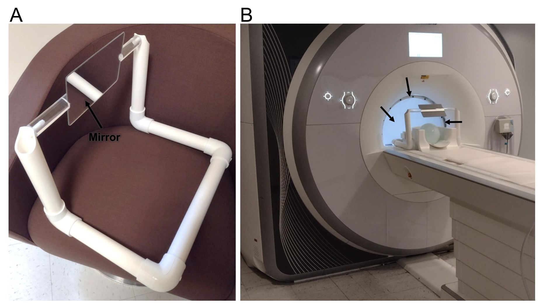
- Place the wide-view screen or mirror 10 cm from the patient's eyes (Figure 1B). Place the bore-sized screen from the back of the scanner bore just behind the head coil. Adjust the position and angle of the mirror/screen for each participant to achieve a consistent viewing angle.
- Ensure that the participant is comfortable throughout the scan via communication through the intercom.
2. fMRI scanning of participant
- Run a localizer scan with three orthogonal planes and scanner adjustments and calibrations for frequency adjustment and shimming.
- Run a T1-weighted magnetization-prepared rapid acquisition gradient echo (MP-RAGE) anatomical scan to help position the echo-planar imaging (EPI) slices.
- Create visual stimuli, as described in the following steps, using a program for running behavioral or psychological experiments.
- At the start of the fMRI protocol, instruct the participant to fixate on the white cross (3° x 3°), which should be on top of a gray background at the center of the stimuli for 10 s.
NOTE: The white cross will be shown before and after each visual stimulation paradigm for 10 s. Thus, the total fMRI stimulation test for each paradigm is 200 s. - Present the first visual stimulation paradigm (a series of rotating wedges) for a period of 30 s (giving an angular velocity of 6°/s) and cycle through six periods. The wedge stimuli should include 12 frames of rotating wedges (one scan with clockwise rotation and one with counterclockwise), extending to the edge of the screen/mirror (>100° visual field), with an 8 Hz contrast-reversing black and white (100% contrast) checkerboard pattern (Figure 2A).
- Present the white cross once again for 10 s.
- Repeat steps 2.4-2.6 with the second visual stimulation paradigm (a series of expanding and contracting rings) for a period of 30 s (expanding or contracting at 1.8°/s of the visual field) and cycles through six periods. The ring stimuli should include eight frames of expanding or contracting rings (>100° visual field), with an 8 Hz contrast-reversing black and white (100% contrast) checkerboard pattern (Figure 2B).
- After completing the fMRI, move the table out of the scanner bore while instructing the participant to remain still. Remove the mirror/screen, place the anterior portion of the head coil in addition to the posterior, and move the table back into the center of the scanner.
- Acquire a quick localizer scan in case of any movement and acquire an MP-RAGE scan with the full head coil.
NOTE: An anatomical image with the whole head coil is needed for accurate registration for group analyses and reconstruction purposes.
Access restricted. Please log in or start a trial to view this content.
Results
Access restricted. Please log in or start a trial to view this content.
Materials
| Name | Company | Catalog Number | Comments |
|---|---|---|---|
| 3T MRI scanner | |||
| 6-32 nylon machine screws, rounded head | |||
| 8-channel head array coil | |||
| Acrylic mirror | |||
| E-Prime | |||
| Rear projection screen |
