This video demonstrates the use of light sheet fluorescence microscopy to image motor neuron projections and axon branching in transgenic mouse embryos. It outlines the steps involved in sample preparation, imaging, and 3D reconstruction of axonal branching for assessing motor neuron growth and connectivity.
A subscription to JoVE is required to view this content. Sign in or start your free trial.
Method Article
Visualizing Motor Neuron Projections and Axon Branching Using Light Sheet Fluorescence Microscopy
1.1K views
⸱
May 29th, 2025
In This Article
Abstract
Protocol
All procedures involving animal samples have been reviewed and approved by the appropriate animal ethical review committee.
1. Light sheet fluorescence microscopy (LSFM) (2–3 h)
- Sample set-up
- Set up 5X/0.1 illumination optics and 5X/0.16 detection optics. Assemble the sample holder and sample capillary (1.5 mm internal diameter, green) and place them into the microscope.
NOTE: Refer to the microscope's Operating Manual for detailed set-up procedures. - Mount the embryo as follows:
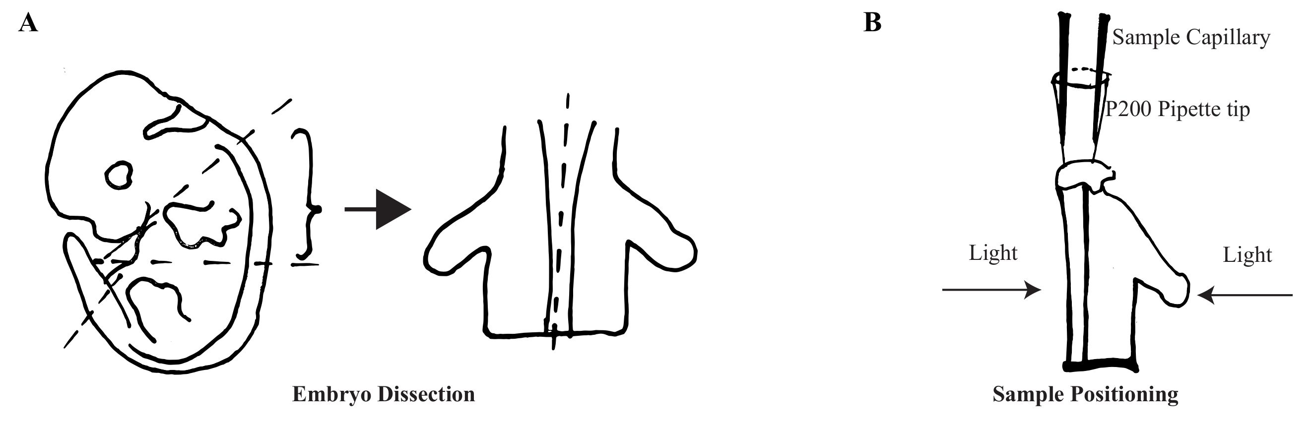
- Prepare the P200 pipette tip by cutting away the upper part so that it fits the diameter of the capillary and remove the pointed part (~ 3 mm) for the sample attachment.
- Melt the blunted end of the pipette tip using a small flame.
- Extinguish the flame and quickly attach the embryo vertically onto the melted end.
- Fit the upper part of the pipette tip with the sample capillary.
- Allow the chamber buffer to equilibrate with the embryo for 1 min to clear off debris or bubbles.
- Using the imaging software, select Locate capillary under the Locate tab and adjust the x, y, and z axes to position the sample capillary.
- Select Locate sample and zoom to 0.6X to focus on the embryo. Rotate the embryo to ensure that the long axis of the imaged limb aligns with the light path of the two light sources (Figure 1B).
- Set up 5X/0.1 illumination optics and 5X/0.16 detection optics. Assemble the sample holder and sample capillary (1.5 mm internal diameter, green) and place them into the microscope.
- Image acquisition
- Under the Acquisition tab, define the light path parameters such as detection objectives, laser blocking filter, beam splitter, cameras, and lasers.
NOTE: The green fluorescent protein (GFP) channel is used in this experiment (Excitation wavelength: 488 nm; emission filter: bandpass (BP) 505 to 545 nm; beam splitter: SPS LP 560). - Check the pivot scan checkbox for shadow reduction.
- Define the acquisition settings: bit depth, 16 bit; zoom, 0.36-0.7X; single-side illumination (left/right) or dual-side illumination.
- Click Continuous and set the laser intensity, exposure time, laser power, and light sheet position to acquire sharper images.
NOTE: The laser power is kept as low as possible to minimize photodamage. - Press STOP to end image acquisition.
- Under the Acquisition tab, define the light path parameters such as detection objectives, laser blocking filter, beam splitter, cameras, and lasers.
- Multidimensional acquisition
- Define the z-stack by moving the Z position for the first and last image. Click Optimal to set the slice number.
- Click Start Experiment to acquire the selected z-stack.
- When it is done, save the image in .czi format.
- Image processing (optional)
- Proceed with Dual side fusion under the Lightsheet Processing channel if dual-side illumination is applied. Multiview processing is necessary if multi-views are acquired to combine images from multiple angles.
- Create a 2D image using data from the highest intensity pixels along the projection axis under the Maximum Intensity Projection channel.
- Under the Copy channel, click Subset to select subsets of images from the original set.
2. Quantification of Axon Arborization (30 Min for Each Individual Nerve)
- Open the image file in the imaging analysis software (by default, the image containing the XYZ data is opened in Surpass mode and as a 3D-rendered view).
- Adjust the image color, brightness, and contrast using the Display Adjustment window (Edit | Show Display Adjustment) to detect filaments based on local intensity contrast.
- Click on the Add New Filaments icon and select the Autopath (no loop) algorithm in the drop-down menu.
- Select the region of interest (in this case, the segmenting axon of interest). Click Next when finished.
- Define the starting and seed points by assigning the largest and thinnest diameter measurements, which can be measured using the Slice mode.
- Assign a starting point at the edge of the region of interest. To achieve manual addition or removal of starting points, first change the pointer mode (Navigate | Select) and then Shift + right-click at the points of interest.
- Select manual thresholds for seed points to ensure that all of the visible arborization is marked. Change the pointer mode (Navigate | Select) and then Shift + left-click at the points of interest to manually add or remove seed points.
NOTE: It is important to manually remove background noises and signals from neighboring nerves. - Check the box Remove seed points around starting points.
- Check Remove disconnected segments to allow the exclusion of points that are too far away, and that may represent background noise. Indicate the Maximum Gap Length in the next step to define the upper limit for exclusion.
- Adjust the threshold for background subtraction, which uses a Gaussian filter to estimate the background intensity of every voxel.
- Set the automatic threshold for dendrite diameter using the Approximate cross-section area algorithm.
- Skip the steps for spine calculation.
- Finish the process and choose the desired style and color.
- Uncheck the volume box in Properties to view only the reconstructed axons.
- Under the Statistics tab, select Detailed. Use Filament No. Dendrite Terminal Points to quantify the motor nerve terminals as an indicator of motor axon arborization.
NOTE: Statistical annotation can be added if desired. - Export the image of the reconstructed axon as a .tif file.
Access restricted. Please log in or start a trial to view this content.
Results
Access restricted. Please log in or start a trial to view this content.
Materials
| Name | Company | Catalog Number | Comments |
|---|---|---|---|
| Hb9::GFP | |||
| 4% Paraformaldehyde (PFA) | |||
| Phosphate buffer saline 10X (PBS 10X) | |||
| Triton X-100 | |||
| Fetal Bovine Serum | |||
| Sheep polyclonal anti-GFP | |||
| Alexa Fluor 488 donkey anti-sheep | |||
| RapiClear 1.47 clearing reagent | |||
| 1.5ml micro tube | |||
| 24 wells plate | |||
| 5 SA Tweezer | |||
| Iris Scissors striaght sharp/sharp | |||
| Microsurgery Scalpels, single use | |||
| Dissecting microscope | |||
| Shaker | |||
| Lightsheet Z.1 microscope | |||
| Imaris 8.4.0 image analysis software | |||
| B6.Cg-Tg(Hlxb9-GFP)1Tmj/J (Hb9::GFP mice) |
