This video demonstrates the use of two-photon microscopy to monitor calcium dynamics in cone photoreceptors of a transgenic mouse retina. It outlines the steps for preparing retinal slices, imaging FRET-based calcium biosensors, and analyzing fluorescence changes to quantify calcium levels under background illumination and light stimulation.
A subscription to JoVE is required to view this content. Sign in or start your free trial.
Method Article
Two-Photon Microscopy for Monitoring Calcium Dynamics in Mouse Retinal Cone Photoreceptors
918 views
⸱
June 17th, 2025
In This Article
Abstract
Protocol
All procedures involving animal samples have been reviewed and approved by the appropriate animal ethical review committee.
- Slice preparation (10 - 15 min)
- Prepare beforehand nitrocellulose filter membranes for retinal slicing and glass coverslips for mounting slices and transferring them to the recording chamber. Cut nitrocellulose filter membrane into approximately 10 x 5 mm sized rectangular pieces using scissors. Cut coverslips into approximately 10 x 5 mm sized rectangular pieces using a glasscutter.
- Slowly immerse a glass slide into the extracellular solution close to the tissue. Gently, pull the retinal slice obtained from HR2.1:TN-XL Ca2+ biosensor mouse onto the glass slide with the ganglion cell side up by grabbing it at the very edge using a pair of forceps. This process reduces mechanical damage and folding of tissue.
- Choose the region of the retina that is related to the respective research question. Cut a rectangular, approximately 1 x 2 mm piece out of the selected retinal region using a curved scalpel blade. Wipe off excess solution around the tissue.
- Place the filter membrane on top of the piece of retina such that the ganglion cell side adheres to the membrane. Immediately, add a drop of extracellular medium onto the membrane to firmly attach the tissue to the membrane.
- Transfer the membrane-mounted retinal tissue to the slicing chamber containing fresh extracellular solution.
- Cut the retina into vertical slices of 200 µm thickness (Figure 1B) using a fresh razor blade attached to a tissue chopper. Change the blade for every retinal piece.
Note: The razor blade needs to be perfectly aligned with the surface of the slicing chamber bottom such that the whole membrane splits simultaneously, as indicated by a “clicking” sound when cutting. Otherwise, the blade may bend and damage the slice. - Glue a single membrane-mounted slice to a glass coverslip by applying high vacuum grease to the membrane ends only (Figure 1C). Keep the glass surface below the retina free from grease.
- Keep coverslip-mounted slices covered by a drop of extracellular solution in the holding chamber – a closed and lightproof container, e.g., a Petri dish with the lid covered with alumin um foil – under a carboxygen atmosphere at room temperature (RT). Introduce carboxygen by bubbling a small water reservoir to keep the atmosphere in the holding chamber humidified; this prevents the slices from drying out.
- Allow slices to rest in the holding chamber for 10 - 15 min before moving them (one by one) to the recording chamber. Slices can be maintained for up to 4-5 hrs in a holding chamber at RT (~21 °C).
2. Two-photon Ca2+ Imaging
- Two-photon microscopy
- Use a Movable Objective Microscope (MOM)-type two-photon microscope.
Note: Any upright two-photon microscope that fulfills the following minimal requirements can be used: It has to be equipped with (a) a pulsed laser tuneable to ~860 nm, (b) a minimum of two simultaneously acquired fluorescence channels, (c) filters for enhanced cyan fluorescent protein (eCFP) and citrine fluorescence, (d) a light stimulator, and (e) software that allows recording time-lapsed image sequences at a frame rate sufficient to resolve the Ca2+ signals of interest. - Start the two-photon imaging system as indicated by the manufacturer. Strictly follow the facility’s laser safety guidelines. Start the laser and tune it to ~860 nm.
- Transfer a slice from the holding chamber to the recording chamber and immediately start perfusing with carboxygenated extracellular solution. Maintain a perfusion flow rate of 2 ml/min and a temperature of 37 °C in the recording chamber.
- Use a 20X 0.95 numerical aperture (NA) water immersion objective. If available, use a charge-coupled device (CCD) camera in combination with an infra-red light-emitting diode (LED) below the recording chamber to locate the retinal slice (Figure 2). Otherwise, locate the slice using two-photon imaging (see 2.1.5).
- Switch to two-photon imaging to view biosensor expression. Turn on the two detection channels for fluorescence imaging of eCFP and citrine.
- Use the image acquisition software that controls the two-photon microscope to scan and select a row of cone terminals for recording (Figure 3A). Set image acquisition to 128 x 16-pixel images (31.25 Hz) or a similar configuration. Restrict scanned area to cone terminals to avoid bleaching photopigments in outer segments.
Note: For the TN-XL calcium sensor (τ = ~0.6 sec for Ca2+ binding, τ = ~0.2 sec for Ca2+ unbinding), a minimum frame rate of ~8 Hz is recommended. - Light stimulation and recording
- Use a sub-stage full-field light stimulator to perform the following steps.
Note: A simple solution for a full-field light stimulator is to use two band-pass-filtered LEDs (e.g., “blue”: 360 band-pass (BP) 12, “green”: 578 BP 10) that match the wavelength sensitivities of mouse cones but at the same time do not overlap with the filters used for fluorescence detection. The light from the LEDs is focused by the condenser through the bottom of the recording chamber (Figure 2). - Turn on the laser and allow cones to adapt to the scanning laser and the stimulus background light (20 - 30 sec) before presenting light stimuli (see 2.2.3) or applying pharmacological agents.
- Start presentation of arbitrary stimuli (e.g., flashes of light, as shown in Figure 3B, C). In the case of the stimulator described in step 2.2.1, generate the stimuli by modulating the intensity of the two LEDs over time using a microprocessor board controlled by customized software.
- Start recording the two fluorescence channels (e.g., at 483 nm for “blue”
- Use a sub-stage full-field light stimulator to perform the following steps.
- Förster resonance energy transfer (FRET)-donor eCFP and at 535 nm for “yellow” FRET-acceptor) simultaneously using the respective image acquisition software (see also 2.1.6). For example, in the case of light flashes (Figure 3B, C), record at least 8 - 10 stimulus presentations (trials).
- Use a Movable Objective Microscope (MOM)-type two-photon microscope.
Access restricted. Please log in or start a trial to view this content.
Results
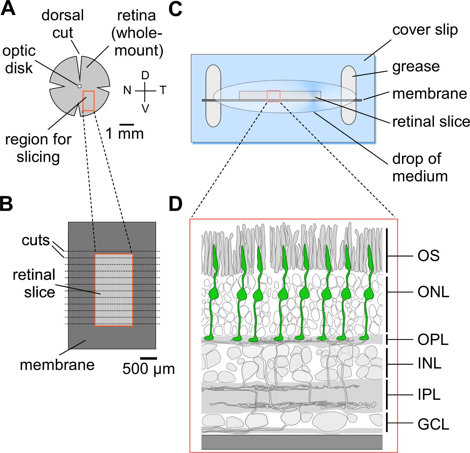
Figure 1. Preparation of vertical retinal slices. (A) Isolated and flattened retina prepared for...
Access restricted. Please log in or start a trial to view this content.
Materials
| Name | Company | Catalog Number | Comments |
|---|---|---|---|
| High vacuum grease | Dow Corning | 1018817 | http://www.dowcorning.com |
| Cover slips | R. Langenbrinck | 24 x 60 mm; http://www.langenbrinck.com | |
| Glass slides | R. Langenbrinck | 76 x 26 mm; http://www.langenbrinck.com | |
| Blades for tissue chopper | MARTOR KG | ARGENTAX No. 1044 | 0.25 mm; http://www.martor.de |
| Tissue chopper | Custom-build | ||
| Nitrocellulose filter membrane gridded | Merck Millipore | AABG01300 | Filter type: 0.8 µm; http://www.emdmillipore.com |
| UV/green LED-based full-field stimulator | Custom-build | ||
| Open source microprocessor board | Arduino | http://www.arduino.cc | |
| Imaging software CfNT | Custom-written | Developed by Michael Müller, MPI for Medical Research, Heidelberg, Germany | |
| IgorPro | Wavemetrics | http://www.wavemetrics.com | |
| VC3-4 System focal perfusion system | ALA Scientific Instrument | With 100 μm-diameter tip manifold; http://www.alascience.com/ | |
| Mai Tai HP DeepSee (Ti:Sapphire laser) | Newport Spectra-Physics | http://www.spectra-physics.com | |
| Movable objective microscope (MOM), Designed by W. Denk, MPImF, Heidelberg, Germany | Sutter Instruments | http://www.sutter.com/MICROSCOPES/index.html | |
| XLUMPlanFL 20x/0.95w objective | Olympus | http://www.olympusamerica.com | |
| Leica MZ95 | Leica microsystems | http://www.leica-microsystems.com/ |
