This video demonstrates live imaging of calcium influx in the lateral-line hair cells of a paralyzed transgenic zebrafish larva using a confocal microscope. Mechanical stimulation of hair bundles via fluid pulses induces calcium entry through mechanotransduction channels and voltage-gated channels, which is visualized in real-time using fluorescence indicators. The method highlights apical and basal calcium dynamics in neuromast hair cells, elucidating their role in water movement detection.
A subscription to JoVE is required to view this content. Sign in or start your free trial.
Method Article
Imaging Calcium Dynamics in Lateral-Line Hair Cells of Larval Zebrafish
751 views
⸱
June 17th, 2025
In This Article
Abstract
Protocol
All procedures involving animal models have been reviewed by the local institutional animal care committee and the JoVE veterinary review board.
- Pinning and Immobilizing Larva to Imaging Chamber
- Bathe a Tg(myo6b:GCaMP6s-caax) larva in approximately 1 mL of embryo buffer (E3) buffer containing 0.04% MS-222 for 1–2 min on the silicone encapsulant surface of the imaging chamber until the larva becomes immobile or unresponsive to touch.
- Under a stereomicroscope, position the larva at the center of the perfusion chamber so it lies flat on its side against the silicone encapsulant.
NOTE: For consistency, always mount larvae on the same side (e.g., right side down, left side up) (Figure 2B1).
- Under a stereomicroscope, position the larva at the center of the perfusion chamber so it lies flat on its side against the silicone encapsulant.
- Using fine forceps, bring a 0.035 mm head pin down perpendicular to the larva and chamber. Insert the head pin between the eye and otic vesicle and down into the encapsulant (Figures 1B1 and 1B2). Use a second set of forceps to stabilize the larva along its dorsal or ventral side while pinning. Ensure that the horizontal part of the pin contacts the larva and does not press all the way into the encapsulant. Angle the pin ventrally (Figure 1B1) or pointing slightly toward the anterior of the fish to avoid interfering with subsequent heart injection and hair-cell imaging.
- Using the forceps, insert a 0.025 mm tail pin into the notochord as close as possible to the end of the tail (Figure 1B1).
NOTE: Be careful to avoid stretching the larva. Pin the larva flat. Eyes should be superimposed (Figure 2B1). This is very important for ease of heart injection (Figure 1B2-B2', step 3), facilitating a desirable imaging plane (Figure 1B1-B2'', steps 5), and quantifying the intensity of the fluid-jet stimulus (Figure 3A3, step 4).
- Using the forceps, insert a 0.025 mm tail pin into the notochord as close as possible to the end of the tail (Figure 1B1).
- Bathe a Tg(myo6b:GCaMP6s-caax) larva in approximately 1 mL of embryo buffer (E3) buffer containing 0.04% MS-222 for 1–2 min on the silicone encapsulant surface of the imaging chamber until the larva becomes immobile or unresponsive to touch.
- Injection of α-Bungarotoxin into the Heart Cavity to Paralyze Larva
NOTE: Wear gloves when handling α-bungarotoxin.
- Centrifuge the α-bungarotoxin aliquot briefly prior to use to prevent clogging of the heart injection needle.
- Backfill 3 µL of α-bungarotoxin solution into a heart injection needle using a gel loading pipette tip. Load the solution evenly to the tip with no bubbles.
- Insert the heart injection needle into a pipette holder attached to a manual micromanipulator. Under a stereomicroscope, position the needle so it is aligned perpendicular to the A-P axis of the pinned and anesthetized larvae, pointing down at an angle of ~30°.
- Connect the pipette holder to the pressure injector. Apply the following suggested settings: Pinjection = 100 hPa, tinjection = 0.5 s, and Pcompensation = 5 hPa. Inject a bolus into the solution to test whether the needle tip is patent.
- Look for a small puff of the red solution (from phenol red) to leave the tip of the needle. If no red color is seen, very gently scrape the needle tip against the edge of a pin and try again until the needle is patent. Alternatively, pull a needle with a larger tip opening.
- Advance the needle toward the heart until it touches the skin outside of the heart (Figure 1B2). Press the needle into the larva and look for indentation of the pigment cell on the skin in front of the heart to ensure that needle is positioned in the correct plane relative to the larva (Figure 1B2').
- Advance the needle further until it pierces the skin and enters the heart cavity. Pull the needle back slightly. Inject a bolus of α-bungarotoxin into the heart cavity. Look for inflation of the heart cavity or for red dye entering the cavity.
- Gently rinse the larva 3 times with 1 mL of neuronal buffer (NB) to remove residual MS-222. Never remove all of the fluid. Maintain larva in approximately 1 mL of NB on the perfusion chamber.
NOTE: Ensure that larval heartbeat and blood flow remain robust after pinning and heart injection and throughout the entire imaging experiment. - Preparation of Microscope and Fluid-jet Setup
- Assemble an upright confocal microscope using the components described in the Table of Materials: a confocal microscope with a 488 nm laser and appropriate filters, microscope software to control and coordinate imaging and stimulation, 10x air objective, 60x water objective, piezo-Z objective scanner (for z-stacks), high-speed camera, circular chamber adaptor, motorized stage, and stage insert adaptor.
- Assemble the fluid jet made up of 3 main components: a vacuum and pressure pump, high-speed pressure clamp, and head stage (also described in the Table of Materials). Use the high-speed pressure clamp to control the timing and duration of pressure or vacuum discharge out of the heads stage and into the fluid-jet pipette.
- Connect the output of the head stage to the fluid-jet pipette holder via thick-walled silicone tubing.
- Alignment of Larva and Fluid-jet
NOTE: There are 3 planes of interest within each neuromast: (1) the tips of the hair bundles (Figure 3A3: the kinocilia, used to measure stimulus intensity); (2) the hair-bundle mechanotransduction (MET) plane (Figure 2B1-B1': the base of the apical hair bundles where MET-channel-dependent calcium signals are detected); and (3) the synaptic plane (Figure 2B2-B2': where presynaptic calcium signals are detected at the base of the hair cell). These planes are outlined in Figure 2A.
- Backfill 10 µL of NB into a properly broken fluid-jet needle using a gel loading tip. Load the solution evenly to the tip with no bubbles. Insert the needle into the pipette holder attached to the motorized micromanipulator.
- Place the perfusion chamber into a circular chamber adapter on the microscope stage.NOTE: For consistency, always position the larva in the same orientation (e.g., the chamber containing the larva with its posterior toward fluid jet and ventral side facing toward the experimenter).
- Move the motorized stage so that the larva is in the center of the field of view. Turn the circular chamber adaptor so that the anteroposterior (A-P) axis of the larva is roughly aligned with the trajectory of the fluid-jet needle.
- Using transmitted light and differential interference contrast (DIC), bring the larva into focus and center it under the 10x objective. Raise the 10x objective.
- Using the motorized micromanipulator, bring the fluid-jet needle down into the center of the field of view so it is illuminated by the transmitted light and barely touching the NB solution.
- Lower the 10x objective. Focus on the larva to confirm its location. Focus up to find the fluid-jet needle. Move the fluid-jet needle with the micromanipulator in the x- and y-axes until it is in a position parallel to the dorsal side of the fish.
- Focus back on the larva. Bring the needle down in the z-axis. Position the needle along the dorsal side of the fish and ~1 mm away from the body (Figure 3A1).
- Carefully move the circular chamber adaptor (if necessary) to ensure that the fluid-jet needle is aligned along the A-P midline of the larva (Figure 3A1).
- Move the motorized stage to place the neuromast of interest in the center of the field of view. Keep the fluid-jet needle tip along the dorsal side of the fish. Do not touch the tip of the fluid-jet needle to the larva or the chamber surface.
- Switch to the 60x water objective. Ensure that the objective is immersed in the NB solution. Use the fine focus to locate a neuromast using transmitted light and DIC optics.
NOTE: This setup is designed to stimulate neuromasts along the primary posterior lateral line. Hair cells within these neuromasts respond to either anterior or posterior directed fluid flow.- Position the fluid-jet needle with the micromanipulator so that it is 100 µm from the outer edge of the neuromast (Figure 3A2).
NOTE: Choose neuromasts that offer clear top-down views (Figures 2B1'-B2' and Figure 3A3) rather than side-angled views (Figure 2C1-C2). A clear top-down view allows for simultaneous imaging of all apical hair bundles in a single optical plane or imaging of synaptic areas in fewer optical planes (Figure 3A3). - Focus up to the tips of the apical hair-bundles (kinocilia) (Figure 1A, Figures 3A2 and 3A3). The bottom of the fluid-jet needle should be in focus in this plane.
- Position the fluid-jet needle with the micromanipulator so that it is 100 µm from the outer edge of the neuromast (Figure 3A2).
- Set the high-speed pressure clamp from the manual to external mode to receive input from the imaging software.
- Zero the high-speed pressure clamp by pressing the "zero" button. Use the set-point knob to set the resting pressure slightly positive (~2 mmHg). Confirm the resting output of the high-speed pressure clamp using a pounds per square inch (PSI) manometer attached to the head stage output.
NOTE: Set a slightly positive pressure at rest to avoid the gradual uptake of fluid into the fluid-jet needle over time. If fluid enters the tubing connected to the fluid-jet and reaches the head stage, it can damage the equipment. - Determine the pressure needed to stimulate the hair bundles. Use a 0.125 and 0.25 V input (6.25 and 12.5 mmHg) for 200–500 ms to apply a test stimulus (Figure 3A3-A3'').
NOTE: The high-speed pressure clamp converts a voltage input (from software or other devices that connect to the Bayonet Neill–Concelman (BNC) port on the high-speed pressure clamp command port) into pressure that is discharged from the head stage, and ultimately, the fluid-jet needle (1.0 V = 50 mmHg, while -1.0 V = -50 mmHg). In this configuration (see step 4.2) positive pressure (push) deflects hair bundles towards the anterior, and negative pressure (pull) deflects hair bundles towards the posterior. - Using transmitted light and DIC optics along with a scale bar, measure the distance of deflection by the 6.25 and 12.5 mmHg stimuli of the tips of the hair bundles, the kinocilia (Figure 2A and Figures 3A3-3''). Choose a pressure that moves the bundles (as 1 cohesive unit) a distance of approximately 5 µm (Figure 3A3''). Ensure that the tips of the kinocilia remain in focus the entire time.
- Move the fluid-jet ± 25 µm along the A-P axis of the larva to find a distance and pressure that deflects the tips of kinocilia 5 µm.
NOTE: Using GCaMP6s in larvae 3–7 days post-fertilization (dpf), a 5 µm deflection should achieve near saturating GCaMP6s calcium signals and should not damage apical hair-bundle structures (Figure 3A3''). Smaller displacement distances can be used to deliver non-saturating stimuli (Figure 3A3'). Displacement distances >10 µm are hard to estimate (Figure 3A3''') and can be damaging over time. Signal saturation is dependent on age of the neuromast (and kinocilial height) as well as the indicator used. Check the patency of the fluid-jet needle in each direction (pressure/push and vacuum/pull) periodically during imaging. Fluid-jet needles clog easily and lose vacuum patency, but they maintain residual pressure patency. Use DIC optics and a short test stimulus in each direction to check for fluid-jet patency. - Focus the sample into the plane of interest (e.g., the base of the apical hair bundles or the base of the hair cell in the synaptic plane; Figure 2B1-B2').
- Zero the high-speed pressure clamp by pressing the "zero" button. Use the set-point knob to set the resting pressure slightly positive (~2 mmHg). Confirm the resting output of the high-speed pressure clamp using a pounds per square inch (PSI) manometer attached to the head stage output.
- Imaging Acquisition Procedure: Single-plane Acquisition
NOTE: All imaging outlined in this protocol is performed at room temperature (RT).
- Set imaging software to acquire a streaming or continuous 80-frame acquisition with a capture every 100 ms to achieve a frame rate of 10 Hz.
- Set gain, aperture, and laser power to optimize signal detection, but avoid saturation, photobleaching, and noise. Example settings for an Opterra/SFC are as follows: 488 nm laser power: 50 (hair-bundle MET plane), 75 (synaptic plane); 35 µm slit; gain = 2.7; EM gain = 3900.
NOTE: Apply 2 X binning if signals are too weak or noisy or have excessive photobleaching. 2 X binning will enhance signal detection at the cost of spatial resolution. - Select a stimulus to deliver during the 80-frame (8 s) acquisition after frame 30, at 3 s.
NOTE: Some example stimuli are as follows: 200 ms (+ or - 0.25 V) up to 2 s (+ or - 0.25 V) step in the anterior or posterior direction to identify the directional sensitivity of each hair cell; 2 s, 5 Hz square wave (0.25 V for 200 ms, -0.25 V for 200 ms, repeated 5 times) to stimulate all hair cells simultaneously. A positive pressure (anterior stimulus) will activate half of the hair cells. A negative pressure (posterior stimulus) will activate the other half of the hair cells. Be sure the stimulus software or device returns the pressure clamp back to 0 V after the stimulus is finished. - Measure mechanosensitive calcium responses. Focus on the base of the apical hair bundles (Figures 2A and 2B1-B1') and start image acquisition.
NOTE: If the neuromast is viewed clearly from the top down (Figure 2B1-B1'), all apical hair bundles can be imaged simultaneously in a single plane. - Measure presynaptic calcium responses. Focus to the base of the hair cells (Figures 2A and 2B2-B2') and start image acquisition.
NOTE: If the neuromast is viewed clearly from the top down (Figure 2B2-B2'), the presynaptic imaging planes of all hair cells can be acquired in 2–3 planes set 2 µm apart. Tg[myo6b:ribeye-mcherry] transgenic fish can be used to identify and locate presynaptic ribbons and sites of calcium entry.
Access restricted. Please log in or start a trial to view this content.
Results
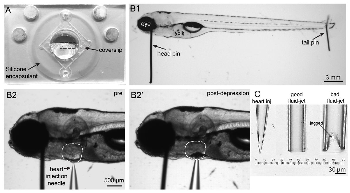
Figure 1: Imaging chamber, zebrafish mounting and heart injection procedures, and needles. (A) Sh...
Access restricted. Please log in or start a trial to view this content.
Materials
| Name | Company | Catalog Number | Comments |
|---|---|---|---|
| α-Bungarotoxin | R&D Systems | 2133 | For paralyzing larvae prior to imaging |
| Imaging chamber | Siskiyou | PC-R | Platform to mount larvae for imaging |
| No. 1.5 Coverslips square, 22*22 mm | VWR | 48366-227 | To seal imaging chamber |
| High vacuum silicone grease | Fischer Scientific | 14-635-5D | For affixing of coverslip to imaging chamber |
| Silicone encapsulant clear 0.5 g kit | Ellsworth Adhesives | Dow Corning Sylgard, 184 SIL ELAST KIT 0.5KG | To fill imaging chamber to create a surface to pin fish |
| Stereomicroscope | Carl Zeiss Microscopy | Stemi 2000 with transmitted light illumination | For illuminating wire, forceps and scissors to make pins |
| Fine forceps | Fine Science Tools | Dumont #5 (0.05 x 0.02 mm) Item No. 11295-10 | For making pins |
| Fine scissors | Cole-Palmer | 5.5", EW-10818-00 | For cutting tunsgten wire to make pins |
| Tungsten wire, 0.035 mm | Goodfellow | W005131 | For head pins to immobilize larvae |
| Tungsten wire, 0.025 mm | ThermoFischer Scientific | AA10405-H4 | For tail pins to immobilize larvae |
| Borosilicate glass capillaries w/o filament | Sutter Instrument Company | B 150-86-10 | Glass to be pulled into fluid-jet needles to stimulate hair cells |
| Fine forceps | Fine Science Tools | Dumont #5 (0.05 x 0.02 mm) Item No. 11295-10 | For pinning larvae |
| Gel loading tips | Eppendorf | 5242956003 | For backfilling heart injection needles |
| Stereomicroscope | Carl Zeiss Microscopy | Stemi 2000 with transmitted light illumination | For illuminating larvae during pinning and heart injection |
| Glass capillary/needle holder | WPI | MPH315 | To hold fluid-jet needles |
| Manual micromanipulator | Narishige | M-152 | For holding and positioning of needle holder to inject α-bungarotoxin |
| Magnetic stand | Narishige | GJ-1 | For holding manual micromanipulator for α-bungarotoxin injection |
| Pressure injector | Eppendorf | Femtojet 4x | To deliver α-bungarotoxin |
| Confocal microscope | Bruker | Swept field/Opterra confocal microscope | Fixed, upright microscope with DIC optics and 488nm laser with appropriate filters |
| Microscope software | Bruker | Prairieview 5.3 | To coordinate and control the microscope, lasers, stage, piezo-z, cameras and fluid jet |
| 10x air objective | Nikon | MRH00101 | Low magnification for positioning of larvae and fluid jet |
| 60x water objective | Nikon | MRF07620 | Water immerison objective with high NA (1.0) and adequate working distance (2.0 mm) |
| Piezo-Z objective scanner with controller/driver | Physik Intruments instruments/Bruker | 01144210/UM-Z-PZ | High-speed z-stack acquisition with 0.025um accuracy |
| EMCCD camera | QImaging | Rolera EM-C2 EMCCD camera | Camera with small pixel size that can acquire up to 100 frames per s |
| Circular chamber adapter | Siskiyou | PC-A | For holding and rotating imaging chamber on microscope stage |
| Motorized Z-deck stage | Prior Scientific | ZDN12MP | Microscope stage that can hold and move sample and micromanipulator with fluid-jet needle together |
| Z-deck stage insert adaptor | NIH Machine shop | custom | To fit the circular chamber adaptor onto the z-deck stage |
| Fluid-jet apparatus | ALA scientific instruments | HSPC-1 High-speed pressure Clamp with PV-PUMP | For controlling and delivering the fluid-jet stimulus |
| Masterflex Peroxide-cured silicone tubing (1 ft) | Cole-Palmer | Masterflex L/S 13, 96400-13 | For connecting the fluid-jet needle holder to pressure pump |
| Motorized micromanipulator | Sutter Instrument Company | MP-225 | For holding and positioning of needle holder for fluid jet |
| Micromanipulator controller | Sutter Instrument Company | MPC-200 | For controlling fluid-jet needle manipulator |
| Gel loading tips | Eppendorf | 5242956003 | For backfilling fluid-jet needles |
| Glass capillary/needle holder | WPI | MPH315 | To hold fluid-jet needles |
| PSI manometer | Sper Scientific | 840081 | For measuring pressure clamp output |
| Prism7 | Graphpad | Prism7 | Software to plot GCaMP6 intensity changes |
| FIJI | Schindelin, et., al.34 | https://fiji.sc/ | Software to process images and create spatio-temporal signal maps |
| Turboreg Plugin | Thévenaz et., al.29 | http://bigwww.epfl.ch/thevenaz/turboreg/ | Plugin to register GCaMP6 image sequences in FIJI |
| StackReg Plugin | Thévenaz et., al.29 | http://bigwww.epfl.ch/thevenaz/stackreg/ | Plugin to register GCaMP6 image sequences in FIJI |
| Times Series Analyzer V3 Plugin | Balaji J 2007, Dept. of Neurobiology, UCLA | https://imagej.nih.gov/ij/plugins/time-series.html | Plugin to create multiple ROIs to measure GCaMP6 intensity changes |
