This report describes the use of a custom-built system to perform aerosol deposition of thick films of yttrium iron garnet onto sapphire substrates at RT. The deposited films are characterized using scanning electron microscopy, profilometry, and ferromagnetic resonance to give a representative overview of the capabilities of the technique.
Method Article
Formation of Thick Dense Yttrium Iron Garnet Films Using Aerosol Deposition
In This Article
Summary
Abstract
Aerosol deposition (AD) is a thick-film deposition process that can produce layers up to several hundred micrometers thick with densities greater than 95% of the bulk. The primary advantage of AD is that the deposition takes place entirely at ambient temperature; thereby enabling film growth in material systems with disparate melting temperatures. This report describes in detail the processing steps for preparing the powder and for performing AD using the custom-built system. Representative characterization results are presented from scanning electron microscopy, profilometry, and ferromagnetic resonance for films grown in this system. As a representative overview of the capabilities of the system, focus is given to a sample produced following the described protocol and system setup. Results indicate that this system can successfully deposit 11 µm thick yttrium iron garnet films that are > 90% of the bulk density during a single 5 min deposition run. A discussion of methods to afford better control of the aerosol and particle selection for improved thickness and roughness variations in the film is provided.
Introduction
Aerosol deposition (AD) is a thick-film deposition process that can produce layers up to several hundred micrometers thick with densities greater than 95% of the bulk1. The deposition process is believed to occur through a continual process of impact, fracture or deformation, adhesion, and densification of particles. Figure 1 depicts this process as a series of steps showing particle impact and densification over several steps. As shown, the particles move toward the substrate with a typical velocity of 100–500 m/sec. As the initial particles impact with the substrate they fracture and adhere to the substrate. This anchoring layer provides the mechanical adhesion between the substrate and the bulk film. As subsequent impacts occur the underlying particles are increasingly fractured, adhered, and further densified. This process of continual impact, fracture, and densification works to compact the underlying film and bond the crystallites and produce a film with a density reaching greater than 95% of the bulk material.
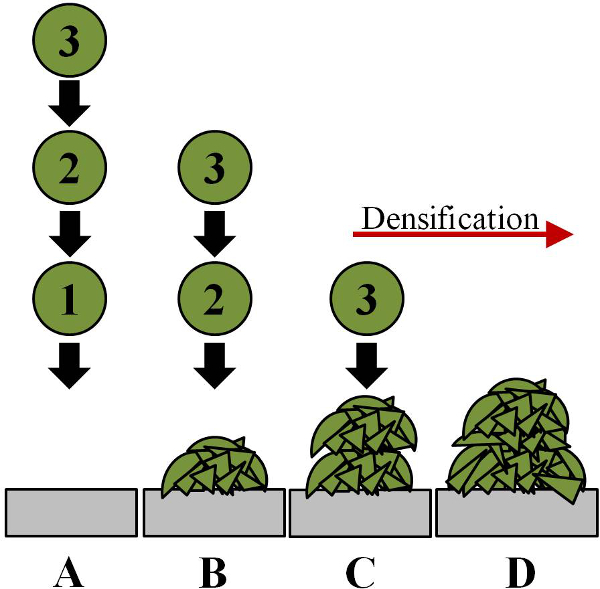
Figure 1. Illustration of the deposition process. Panel A shows three particles moving toward the substrate with a typical velocity of 100–500 m/sec. Panel B shows the result of impact, fracture, and adhesion of the first particle. Panels C and D show the subsequent impact of the second and third particles, which further compact the underlying film and bond the crystallites. The result is a film with density greater than 95% of the bulk material (reproduced with permission from Reference 19). Please click here to view a larger version of this figure.
The primary advantage of AD is that the deposition takes place entirely at ambient RT; thereby enabling film growth, for instance, of a high-melting-temperature material (starting powder) onto a low-melting-temperature substrate. The deposition rate can be up to several micrometers per minute and is performed at moderate vacuum conditions of 1–20 Torr in the deposition chamber. The process shows the ability to scale up to very large deposition areas and finally, it can deposit conformally.2
There are many material systems studied by AD for a wide variety of uses, such as inductors3, abrasion-resistant coatings4, piezoelectrics5, multiferroics6, magnetoelectrics7 thermistors8, thermoelectric films9, flexible dielectrics10, hard tissue implants and bioceramics11, solid electrolytes12, and photocatalysts13. For applications to microwave devices, magnetic films of several hundreds of micrometers in thickness are required that would ideally be integrated directly into the circuit board elements. One challenge to realizing this integration is the high-temperature regime needed for fabricating ferrite films (see review by Harris et al.14), such as yttrium iron garnet (YIG). For this reason AD appears to be a natural choice for realizing potential new advancements in magnetic integrated circuit technology. The low-cost operation, high deposition rate, and simplicity of AD has spurred interest by researchers in Germany, France, Japan, Korea, and now in the United States.
Figure 2 is a drawing outlining the basic setup to perform aerosol deposition. Pressure is monitored at the locations marked PAC, PDC, and PH for the aerosol chamber, deposition chamber, and pump head, respectively. The gas flow, controlled by the mass flow controller (MFC), enters the aerosol chamber and aerosolizes the powder. The deposition chamber is pumped to create the pressure difference between the two chambers, causing the flow of particles through the rectangular (0.4 mm x 4.8 mm) nozzle opening.
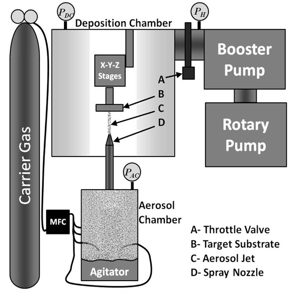
Figure 2. Main components in the NRL ADM system. Pressure is monitored at the locations marked PAC, PDC, and PH for the aerosol chamber, deposition chamber, and pump head, respectively. See text for details. (copyright (2014) The Japan Society of Applied Physics, reproduced from Reference 20). Please click here to view a larger version of this figure.
The average size of an individual YIG particle in this work is 0.5 µm. The effect of agglomeration causes these small particles to form much larger agglomerates that range in size from about 10 µm to about 400 µm. Control of the agglomerate size and delivery rate is essential to achieving a dense well-formed film. This necessitates configuration of an aerosol chamber that allows size selection and uniform particle flux into the deposition chamber. The powder is pre-sieved to remove any agglomerates larger than 53 µm prior to being loaded into the aerosol chamber. The aerosol chamber configuration used in this work is illustrated in Figure 3. Nitrogen gas enters through four inlet nozzles (two are shown in Figure 3) located at the bottom sides of the chamber. The gas interacts with the YIG powder (shown in green) to produce an aerosol comprised of a distribution of agglomerated particle sizes less than 53 µm. An agitator at the base of the aerosol chamber made of a stainless steel plate is vibrated continuously to keep the powder moving into the gas flow. The agglomerates impact a 45 µm filter, allowing only agglomerates sized less than 45 µm to enter the nozzle inlet. Upon entering the nozzle inlet the agglomerates are accelerated to a large velocity and ejected into the deposition chamber (not shown) to perform the deposition. A stainless steel rod connects the bottom of the filter to the base of the agitator (not shown) to aid in de-clogging the filter.
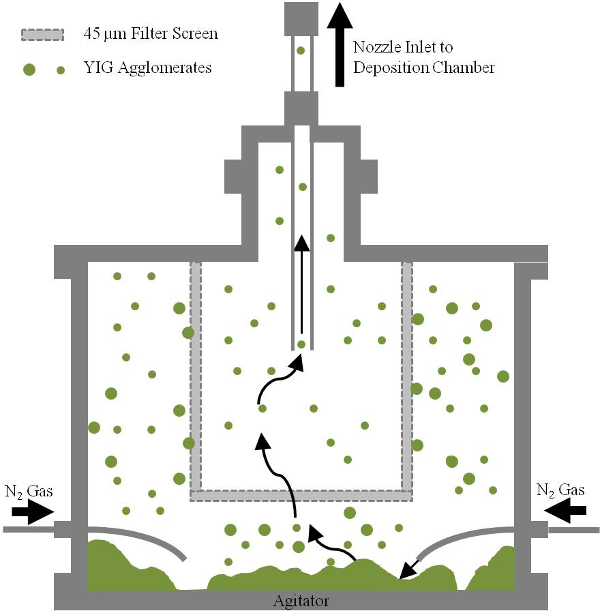
Figure 3. Illustration of the internal aerosol chamber configuration, with filter, inlet nozzles, and YIG powder shown. See text for details.
This report details the experimental procedure to perform AD using the custom-built system described above to produce dense films of YIG. Representative results for an 11 µm thick film produced in this system are presented using scanning electron microscopy (SEM), thickness profiles, and ferromagnetic resonance (FMR). The results presented are not intended to be an in-depth study of the magnetic properties or material structure of the film, but as a demonstration of the films produced by this technique. Please click here to view a larger version of this figure.
Access restricted. Please log in or start a trial to view this content.
Protocol
1. Powder Preparation
- Sieve as-received yttrium iron garnet (YIG) powder to obtain 100–150 g of agglomerates sized less than 53 µm.
- Place the sieved powder into a furnace to dry for at least 24 hr at a temperature greater than 300 °C.
2. Substrate Preparation
- Clean a substrate of desired size, e.g., 3 mm x 3 mm using acetone then isopropanol. Dry using nitrogen gas.
3. Performing Aerosol Deposition
- Mount the sample to the translation mounting stage.
- Place double-sided copper tape to the mounting stage. Place the cleaned substrate onto the copper tape.
- Measure the distance from the edge of the mounting stage to each edge of the sample. Record the dimensions and sample position on the sample history sheet.
- Check that the mounting stage is aligned parallel with the body of the translation motor by measuring the distance from the edge of the mounting stage to the edge of the motor body with calipers. Load the sample into the deposition chamber.
- Clamp the flange to seal the deposition chamber. Attach the 3 15-pin D-sub controller cables for the translation motors.
- Load the powder and close up the aerosol chamber.
- Remove the dried powder from the furnace and place it in the aerosol chamber bottom section. Slide the filter de-clogging rod attachment onto the filter de-clogging rod.
- Place the main body of the aerosol chamber onto the aerosol chamber bottom section. Allow the filter de-clogging rod attachment to rest on the agitation plate as the main body is being attached to the bottom section.
- Clamp the main body to the bottom section. Attach the aerosol chamber pressure gauge to the side port on the main body of the aerosol chamber.
- Clamp the nozzle inlet section to the top port on the main body of the aerosol chamber using a QF clamp. Raise the nozzle inlet tube to the inlet port on the deposition chamber and secure the top and bottom fitting.
- Record the powder and aerosol chamber identification numbers on the sample history sheet.
- Turn on the roughing pump with it isolated from the rest of the system. Turn on the deposition chamber illumination lamp. Open the constriction valve on the bypass line to begin the pump-down of the entire system.
- Setup the pressure monitoring software with the deposition run identification.
- Run the stage controller macro creator by typing ‘pitrans’ in the command line terminal window and enter the requested information. Create a new sheet in the run log spreadsheet and record the deposition parameters and setup notes.
- After the system pressure has reached about 150–200 Torr, slightly open the unconstricted valve. Maintain a pump-down rate of about 1 Torr/sec. Once the pressure has dropped below 100 Torr start the pressure monitoring software and the translation stage motor controller software.
- Once the system pressure has reached about 1 Torr close all three valves to the bypass line and open the main pumping valve. Tighten the clamp to the top cap on the deposition chamber.
- Turn on the blower pump. Open the ultra-high purity (UHP) nitrogen gas cylinder. Monitor the pressure and record the base pressure of the system (it typically reaches 15–25 mTorr).
- Set the distance between the nozzle and the substrate. Use the stage controller software graphical user interface window to move the mounted substrate over the nozzle. Lower the substrate until it contacts the nozzle. Move the substrate 7.5 mm in the vertical direction from this position.
- Close the main pumping line and monitor the leak rate of the system on the pressure monitoring software. Note the initial leak rate upon shutting the valve. If this leak rate is less than 3.33 mTorr/sec continue, otherwise begin checking for leaks. A typical leak rate is less than 1.2 mTorr/sec.
- Set the deposition chamber butterfly valve to the 500 Torr preset value. Set the mass flow controller value to 13.63 L/min (do not turn it on).
- Move the mounting stage to the starting position for the deposition. Load the macro created in step 3.7 into the controller software.
- Program the function generator to sweep linearly between 135 and 145 Hz every 10 sec. Turn the function generator on. Turn the nitrogen gas flow on. After a 3 sec countdown start the stage controller macro.
- Monitor the deposition and adjust gas flow rate as necessary to keep the pressure difference at 500 ± 0.5 Torr (or as desired for the run) for the duration of the deposition.
Note: The pressure in the deposition chamber is typically 0.65 Torr and the pressure in the deposition chamber is typically 501 Torr. Uncontrollable variations in pressure usually indicate that the UHP nitrogen is running out. A slight drop in pressure (1–2 Torr) over the duration of the run is typical. This can be remedied by increasing the gas flow rate. During the initial passes a visible film should form on the substrate, lack of film formation suggests insufficient aerosolization of the powder and/or significant filter clogging. - At the end of the deposition note the exact deposition run time. Shut off the nitrogen gas, the function generator, and the pumps. Open the deposition chamber butterfly valve completely.
- Open the bypass valve located at the side of the deposition chamber. Turn the house nitrogen gas regulator to zero and redirect it into the deposition chamber. Close the main pumping valve while slowly increasing the house gas regulator pressure.
- Home the nozzle to X = 25 mm, Y = 25 mm, and Z = 25 mm, then close the stage controller software.
- Once the pressure in the system has risen above 100 Torr stop the pressure monitoring software. Record the total nitrogen gas used and time to complete the deposition. Adjust the house gas pressure as necessary until the system reaches atmosphere.
- Unplug the 3 15-pin D-sub stage controller cables and unclamp the top cap. Remove the top cap from the deposition chamber and unmount the sample.
4. Post-deposition Inspection
- Remove the sample from the mounting stage and inspect it under a microscope. If necessary, wash the sample in isopropanol to remove loose powder. Perform the planned characterizations of the film.
Access restricted. Please log in or start a trial to view this content.
Results
After the deposition is complete, the coated substrates are removed from the deposition chamber and inspected using an optical stereo microscope. Samples are typically brushed and washed with isopropanol to remove excess powder that remained during re-pressurization to atmosphere. Film characterization was performed on the representative results presented here using scanning electron microscopy to assess the morphology of the film, profilometry to assess the film thickness, uniformity, and roughness, and ferromagnetic re...
Access restricted. Please log in or start a trial to view this content.
Discussion
The SEM image in Figure 4 indicates that significant fracture and densification is occurring during the deposition process. The image is taken of the top surface of the film, which shows a small number of voids and grains. The observable region is the last of the material to be deposited and therefore does not benefit from the further impact and densification process of subsequent particles as illustrated by impact from particle 2 and 3 in Figure 1. The film density within the volume of ...
Access restricted. Please log in or start a trial to view this content.
Disclosures
The authors have nothing to disclose.
Acknowledgements
SDJ gratefully acknowledges the support of the American Association for Engineering Education/NRL Postdoctoral Fellowship Program, discussions with Konrad Bussmann (NRL) and Mingzhong Wu (Colorado State University) on the magnetic properties of materials, and Ron Holm (NRL) for his part in the design and implementation of the NRL AD system.
Access restricted. Please log in or start a trial to view this content.
Materials
| Name | Company | Catalog Number | Comments |
|---|---|---|---|
| Ferromagnetic Resonance Spectrometer | www.bruker.com/ | 9.5 GHz Spectrometer | |
| Scanning Electron Microscope | www.zeiss.com | LEO Supra 55 | |
| Profilometer | www.kla-tencor.com/ | D-120 | |
| Stereo Microscope | www.microscopes.com | Omano Stereo Microscope | Used for inspection directly after removal from deposition chamber |
| Double-sided Copper Tape | www.2spi.com | 05085A-AB | hold-down clips or other adhesives may be used |
| Nitrile Exam Gloves | www.fishersci.com | 19-130-1597D | |
| 2-propanol | www.fishersci.com | A451SK-4 | |
| Acetone | www.fishersci.com | A11-1 | |
| Yttrium Iron Garnet Powder | www.trans-techinc.com/ | Call for Product Information | Powder is custom made to order and ground to specifications |
| Stainless Steel Spoon | www.fishersci.com | 14-429E | Used for scooping and transferring powder |
| Alumina Boats | www.coorstek.com/ | 65580 | |
| Drying Furnace | www.paragonweb.com | KM14 ceramic furnace | Furnace is connected to air during drying |
| Powder Sieves | www.advantechmfg.com/ | 270SS8F | A selection of mesh openings are needed to sieve from large down to target size |
| Ultra High Purity Nitrogen Gas | www.praxairdirect.com | NI 5.0UH-3K | Used as medium for aerosol. |
| Air Breathing Quality | www.praxairdirect.com | AI BR-4KN | Used inside furnace during drying |
| Lab Balance | www.balances.com/ | Sartorius ED224S Lab Balance | Used for weighing powder |
| Sapphire Wafers | www.pmoptics.com/ | PWSP-313211 |
References
- Akedo, J. Room Temperature Impact Consolidation (RTIC) of Fine Ceramic Powder by Aerosol Deposition Method and Applications to Microdevices. J. of Therm. Spray tech. 17, 181(2008).
- Hahn, B. D., Park, D. -S., Choi, J. -J., Ryu, J. Osteoconductive hydroxyapatite coated PEEK for spinal fusion surgery. Appl. Surf. Sci. 283, 6-11 (2013).
- Johnson, S. D., et al. Aerosol Deposition of Yttrium Iron Garnet for Fabrication of Ferrite-Integrated On-Chip Inductors. IEEE Trans. on Magnetics. 51 (05), (2015).
- Johnson, S. D., Kub, F. J., Eddy, C. R. ZnS/Diamond Composite Coatings for Infrared Transmission Applications Formed by the Aerosol Deposition Method. Proceedings of SPIE. 8708, 87080T-87081T (2013).
- Han, G., Ryu, J., Yoon, W. -H., Choi, J. -J. Effect of electrode and substrate on the fatigue behavior of PZT thick. Ceram. Int. 38 (1), S241-S244 (2012).
- Ryu, J., Baek, C. -W., Lee, Y. -S., Oh, N. -K. Enhancement of Multiferroic Properties in BiFeO3-Ba(Cu1/3Nb2/3)O-3. Film. J. Am. Ceram. Soc. 94 (2), 355-358 (2011).
- Park, C. -S., Ryu, J., Choi, J. -J., Park, D. -S. Giant Magnetoelectric Coefficient in 3-2 Nanocomposite Thick Films. Jpn. J. Appl. Phys. 48 (8), 1(2009).
- Ryu, J., Park, D. -S., Schmidt, R. In-plane impedance spectroscopy in aerosol deposited NiMn2O4 negative. J. Appl. Phys. 109 (11), 112722(2011).
- Yoon, W. -H., Ryu, J., Choi, J. -J., Hahn, B. -D. Enhanced Thermoelectric Properties of Textured Ca3Co4O9 Thick Film by Aerosol Deposition. J. Am. Ceram. Soc. 93 (8), 2125-2127 (2010).
- Ryu, J., Kim, K. -Y., Choi, J. -J., Hahn, B. -D. Flexible Dielectric Bi1.5Zn1.0Nb1.5O7 Thin Films on a Cu-Polyimide Foil. J. Am. Ceram. Soc. 92 (2), 524-527 (2009).
- Hahn, B. -D., Lee, J. -M., Park, D. -S., Choi, J. -J. Mechanical and in vitro biological performances of hydroxyapatite-carbon. Acta Biomater. 8 (8), 3205-3214 (2009).
- Choi, J. -J., Cho, K. -S., Choi, J. -H., Ryu, J. Effects of annealing temperature on solid oxide fuel cells containing (La,Sr) (Ga,Mg,Co)O3-δ electrolyte prepared by aerosol deposition. Mater. Lett. 70, 44-47 (2012).
- Ryu, J., Hahn, B. -D. Porous Photocatalytic TiO2 Thin Films by Aerosol Deposition. J. Am. Ceram. Soc. 93 (1), 55-58 (2010).
- Harris, V. G., et al. Recent advances in processing and applications of microwave ferrites. J. of Magn. and Magn. Mat. 321, 2035(2009).
- Kang, Y. -M., Ulyanov, A. N., Yoo, S. -I. FMR linewidths of YIG films fabricated by ex situ post-annealing of amorphous films deposited by rf magnetron sputtering. Phys. Stat. Sol. (a). 204 (3), 763-767 (2007).
- Popova, E., et al. Perpendicular magnetic anisotropy in ultrathin yttrium iron garnet films prepared by pulsed laser deposition technique). J. of Vac. Sci. Techn. A. 19 (5), 2567-2570 (2001).
- Sun, Y., et al. Growth and ferromagnetic resonance properties of nanometer-thick yttrium. Appl. Phys. Lett. 101 (15), 082405(2012).
- Kalarickal, S. S., Krivosik, P., Das, J., Kim, K. S., Patton, C. E. Microwave damping in polycrystalline Fe-Ti-N films: Physical mechanisms and correlations with composition and structure. Phys. Rev. B. 77, 054427(2008).
- Johnson, S. D. Advances in Ferrite-Integrated On-Chip Inductors Using Aerosol Deposition. Magnetics Business & Technology Magazine. 10, (2014).
- Johnson, S. D., Glaser, E. R., Cheng, S. -F., Kub, F., Eddy Jr,, R, C. Characterization of As-Deposited and Sintered Yttrium Iron Garnet Thick Films Formed by Aerosol. Appl. Phys. Express. 7, 035501(2014).
- Lee, D. -W., Nam, S. -M. Factors Affecting Surface Roughness of Al2O3 Films Deposited on Cu Substrates by an Aerosol Deposition Method. J. of Ceramic Proc. Research. 11, 100(2010).
- Glass, H. L., Elliott, M. T. Attainment of the Intrinsic FMR Linewidth in Yttrium Iron Garnet Films Grown by Liquid Phase Epitaxy.J. Cryst. Growth. 34, 285(1976).
Access restricted. Please log in or start a trial to view this content.
Reprints and Permissions
Request permission to reuse the text or figures of this JoVE article
Request Permission