This protocol describes the use of the Ramsay assay to measure fluid secretion rates from isolated Malpighian (renal) tubules from Drosophila melanogaster. In addition, the use of ion-specific electrodes to measure sodium and potassium concentrations in the secreted fluid, allowing calculation of transepithelial ion flux, is described.
A subscription to JoVE is required to view this content. Sign in or start your free trial.
Method Article
Use of the Ramsay Assay to Measure Fluid Secretion and Ion Flux Rates in the Drosophila melanogaster Malpighian Tubule
In This Article
Summary
Abstract
Modulation of renal epithelial ion transport allows organisms to maintain ionic and osmotic homeostasis in the face of varying external conditions. The Drosophila melanogaster Malpighian (renal) tubule offers an unparalleled opportunity to study the molecular mechanisms of epithelial ion transport, due to the powerful genetics of this organism and the accessibility of its renal tubules to physiological study. Here, we describe the use of the Ramsay assay to measure fluid secretion rates from isolated fly renal tubules, with the use of ion-specific electrodes to measure sodium and potassium concentrations in the secreted fluid. This assay allows study of transepithelial fluid and ion fluxes of ~20 tubules at a time, without the need to transfer the secreted fluid to a separate apparatus to measure ion concentrations. Genetically distinct tubules can be analyzed to assess the role of specific genes in transport processes. Additionally, the bathing saline can be modified to examine the effects of its chemical characteristics, or drugs or hormones added. In summary, this technique allows the molecular characterization of basic mechanisms of epithelial ion transport in the Drosophila tubule, as well as regulation of these transport mechanisms.
Introduction
Renal epithelial ion transport underlies organismal iono- and osmoregulation. The Drosophila melanogaster Malpighian (renal) tubule offers an unparalleled opportunity to study the molecular mechanisms of epithelial ion transport. This is due to the combination of the powerful genetics of Drosophila, paired with the accessibility of its renal tubules to physiological study. The Ramsay assay, named after the investigator who pioneered the technique1, measures fluid secretion rates from isolated Malpighian tubules, and was established in Drosophila in 1994 by Dow and colleagues2. This paved the way for further studies using Drosophila genetic tools, such as the GAL4-UAS system3,4, to define cell-specific signaling pathways regulating fluid secretion. An example includes calcium signaling in response to a peptide hormone5, amongst many others6,7.
A combination of genetic techniques and classical physiological study has shown that urine generation in the fly occurs through the secretion of a potassium chloride-rich fluid from the main segment of the tubule. This occurs through the parallel transepithelial secretion of cations, primarily K+ but also Na+, through the principal cell, and Cl- secretion through the stellate cell8-12. The ability to separately measure transepithelial K+ and Na+ fluxes allows a more detailed characterization of transport mechanisms than the measurement of fluid secretion alone. For example, in unstimulated Drosophila tubules, the Na+/K+-ATPase inhibitor ouabain has no effect on fluid secretion2, even when its uptake into principal cells is inhibited by the organic anion transporter inhibitor taurocholate13. However, Linton and O’Donnell showed that ouabain depolarizes the basolateral membrane potential, and increases Na+ flux9. As shown in the Representative Results, we replicated these findings, and showed that K+ flux is concomitantly decreased14; the increased Na+ flux and decreased K+ flux have opposing effects on fluid secretion, resulting in no net change in secretion. Thus, there are two resolutions to the “ouabain paradox,” i.e., the initial observation that ouabain has no effect on fluid secretion in the Drosophila tubule: first, in stimulated tubules, the effect of ouabain on fluid secretion is not apparent due to its uptake by the organic anion transporter13; and second, in unstimulated tubules, ouabain has opposing effects on transepithelial Na+ and K+ flux, resulting in no net change in fluid secretion (see Representative Results and ref. 9). Therefore, the primary role of the Na+/K+-ATPase in unstimulated tubules is to lower intracellular Na+ concentration to generate a favorable concentration gradient for Na+-coupled transport processes across the basolateral membrane. Indeed, by separately measuring Na+ and K+ fluxes, we demonstrated that tubules lacking the fly sodium-potassium-2-chloride cotransporter (NKCC) have decreased transepithelial K+ flux, with no further decrease after ouabain addition, and no change in transepithelial Na+ flux14. These findings supported our conclusion that Na+ entering the cell through the NKCC is recycled through the Na+/K+-ATPase. In another example, Ianowski et al. observed that lowering bath K+ concentration from 10 mM to 6 mM decreased transepithelial K+ flux and increased transepithelial Na+ flux in tubules from Rhodnius prolixus, with no net change in fluid secretion15. Differential effects on Na+ flux and K+ flux across larval tubules have also been observed in Drosophila tubules in response to varying salt diets16 and in two mosquito species in response to rearing salinity17.
The greatest challenge in the measurement of transepithelial ion flux in the Ramsay assay preparation is the determination of ion concentrations within the secreted fluid. This challenge has been met with varying solutions, including flame photometery18, use of radioactive ions19, and electron probe wavelength dispersive spectroscopy20. These techniques require transfer of the secreted fluid drop to an instrument for measurement of ion concentrations. Since the volume of fluid secreted by the unstimulated Drosophila tubule is small, typically ~0.5 nl/min, this poses a technical challenge and also introduces error if some of the secreted fluid is lost upon transfer. In contrast, the use of ion-specific electrodes allows the measurement of ion activity (from which ion concentration can be calculated) in situ. The current protocol was adapted from that used by Maddrell and colleagues to measure transepithelial K+ flux across the Rhodnius tubule using valinomycin as the K+ ionophore21, and also describes the use of a 4-tert-butylcalix[4]arene-tetraacetic acid tetraethyl ester-based Na+-specific ion-specific electrode characterized by Messerli et. al.22. Ion-specific electrodes have also been used to measure ion concentrations in fluid secreted by Malpighian tubules in the Ramsay assay in adult9,23 and larval16Drosophila melanogaster, the New Zealand Alpine Weta (Hemideina maori)24 and in mosquitoes17.
Here, we describe in detail the use of the Ramsay assay to measure fluid secretion rates in Malpighian tubules from Drosophila melanogaster, as well as the use of ion-specific electrodes to determine the concentrations of K+ and Na+ within the secreted fluid and thus the calculation of transepithelial ion fluxes. An overview of the assay is provided in Figure 1.
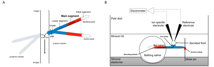
Figure 1. Schematic of the Malpighian Tubules and the Ramsay Assay with Use of Ion-specific Electrodes to Measure Ion Concentrations. This figure illustrates the setup for the Ramsay assay. (A) Each fly has four tubules, a pair of anterior tubules and a pair of posterior tubules, that float in the abdominal cavity surrounded by hemolymph. In each pair, the two tubules join at the ureter, which then empties the urine at the junction of the midgut and hindgut. The tubules are blind-ended. Urine is generated by the fluid-secreting main segment (shown in red), and flows toward the ureter and out into the gut. After dissection, the tubule pair is dissociated from the gut by transecting the ureter. (B) The pair of tubules is then transferred into a droplet of bathing saline within a well of the assay dish. One of the two tubules, referred to here as the “anchor tubule,” is wrapped around a metal pin and is inert. The other tubule is the secreting tubule. The initial segment (which does not secrete fluid) and main segment of the secreting tubule remain within the droplet of bathing saline. Ions and water move from the bathing saline and into the tubule lumen of the main segment, and then move toward the ureter, as would occur in vivo. The lower segment (blue) is outside the bathing saline and therefore inert. Since the ureter is cut, the secreted fluid emerges as a droplet from the cut end of the ureter. The secreted fluid droplet enlarges over time as secretion continues, and its diameter is measured using an ocular micrometer. A layer of mineral oil prevents evaporation of the secreted fluid. The reference and ion specific electrodes measure the ion concentration of the secreted fluid. Please click here to view a larger version of this figure.
Access restricted. Please log in or start a trial to view this content.
Protocol
1. Preparing the Dissection, Calibration and Assay Dishes
Note: In this step, three plastic petri dishes lined with silicone elastomer are prepared: one for dissection, one for performing the Ramsay assay (“assay dish”), and one for performing calibration. These dishes are re-used from experiment to experiment, and thus this step only needs to be repeated if a dish breaks. A picture of the assay dish is shown in Figure 2.
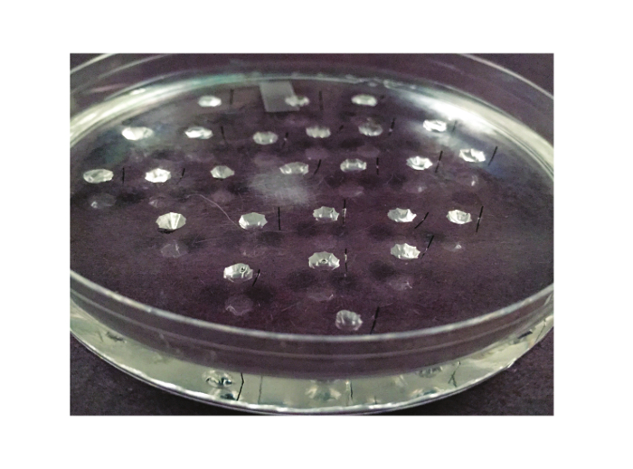
Figure 2. The Assay Dish. The dish used for the Ramsay assay is shown here. It is a 10 cm petri dish that is lined with silicone elastomer. Between 20 and 25 wells are carved out of the elastomer. A Minutien metal pin, cut in half, is placed to the right of each well (or to the left, if the experimenter is left-handed). Please click here to view a larger version of this figure.
- Using gloves, pour ~80 g silicone elastomer base into a glass beaker. Add 1/10 weight (8 g) silicone elastomer cure. Stir with a metal stirrer. Place on an orbital shaker with a flat top at a gentle speed, for example 100 rpm, for several hours until all bubbles have been removed.
- Pour the silicone elastomer into clean plastic petri dishes: 100 mm x 15 mm dishes for the dissection and assay dishes, and 35 x 10 mm for the calibration dish. The thickness of the elastomer layer should be ~6 - 7 mm for the 100 mm dishes, and ~5 mm for the 35 mm dish.
- Place the dishes on the bench at room temperature (RT) to cure (harden), ~24 - 48 hr.
- Once the assay dish has cured, prepare a smaller batch of silicone elastomer as in step 1.1, e.g., 10 g silicone elastomer base with 1 g cure. Shake on orbital shaker as in step 1.1 until air bubbles are no longer present. This elastomer will be used in step 1.5.4 and should not be allowed to harden prior to that step.
- Using a surgical scalpel and standard sharps precautions, make wells in one of the 100 mm silicone elastomer-coated petri dishes. This will be the assay dish.
- Make wells ~1 cm apart and with a diameter of ~3 - 4 mm. 25 wells can easily fit in a 100 mm assay dish. Wells should be at least 6 mm removed from the walls of the dish. Figure 2 illustrates the spacing of the wells. Each well will contain one fluid-secreting tubule during the experiment. Thus, a dish containing 25 wells will allow 25 tubules to be analyzed.
- Use a permanent marker to mark the position of the wells if needed.
- Make the walls of the well as smooth as possible by placing the scalpel in the elastomer, and then using the opposite hand to rotate the dish 360°.
- Then, using standard sharps precautions, dip a 30 G needle into the non-hardened elastomer from step 1.4 and place a small drop at the bottom of each well. This smoothens out the bottom of the well. Allow to cure (harden) x 24 - 48 hr.
- Prepare the Minutien pins.
- Place 0.15 mm black anodized Minutien pins in a row on a piece of 1 inch standard lab labeling tape. The pins’ long axis should be orthogonal to the tape’s long axis. Cut the tape along its length in order to sever each pin into two approximately equal halves (Figure 3). Use one half-pin for each well.
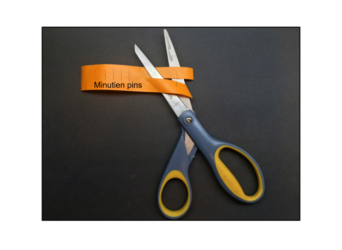
Figure 3. Cutting the Minutien Pins. The pins are lined up on a piece of labeling tape in parallel. Then, scissors are used to cut the pins in half. Please click here to view a larger version of this figure.
- Insert each half-pin into the silicone elastomer approximately 1 mm to the right of each well (if right-handed; if left-handed, insert the pin to the left of each well). This is most easily done when visualizing the wells at low power under a dissecting stereomicroscope and is aided by use of a blunt forceps. Figure 2 illustrates the positioning of the pins.
2. Preparing Fine Glass Rods
Note: In this step, a glass rod is prepared that will be used to transfer the tubules from the dissecting dish into the bathing drop. The glass rod is re-used from experiment to experiment, so this step is performed only once unless the rod breaks and a new one is needed.
- Obtain sheets of 3 mm (1/8 inch) thick stained black glass from a hobby store and appropriate glass-cutting equipment, such as a glass cutter and pliers. Use appropriate safety equipment (thick gloves, goggles).
- Cut the glass into strips ~ 6 mm wide x 10 cm long
- Hold a glass strip in each hand. Soften the short end of each strip over the flame of a Bunsen burner, using appropriate safety precautions. Then, push the ends of the two strips together and pull apart in a smooth movement to create a fine glass rod with a handle.
3. Physiology Setup
Note: In this step, the microscope, electrometer and electrical circuit is set up. Other than periodic re-chloriding (step 3.2) of the silver wires and re-calibration of the electrometer (step 3.8), this step is performed only once. Figure 4 illustrates the setup.
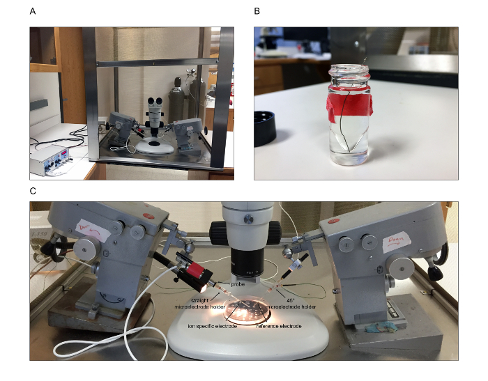
Figure 4. Physiology Setup. The physiology setup is pictured here. (A) Overview of the setup. The stereomicroscope is placed inside the Faraday cage with the micromanipulators on either side. A fiber optic light is threaded through a hole in the side of the Faraday cage. The electrometer is placed outside the Faraday cage. (B) To chloride coat the silver wires, the wire is immersed into bleach. (C) Close-up of the setup. The straight microelectrode holder, shown in this picture on the left, is threaded onto the probe of the electrometer. The ion-specific electrode will then be threaded over the silver wire into the electrode holder. On the right, the reference electrode is threaded over the silver wire of the 45° microelectrode holder. The circuit must then be appropriately grounded. The assay dish is shown as it will be positioned when performing measurements. Please click here to view a larger version of this figure.
- Place the stereomicrosope with ocular micrometer inside the Faraday cage. Ground to the interior of the Faraday cage, which is then grounded to the chassis ground of the electrometer. Place the micromanipulators on either side of the microscope (Figure 4A).
- Chloride two silver wires by immersing in bleach for at least 1 hr. Extend overnight (O/N) if necessary (Figure 4B). Repeat this step whenever the silver wires need to be re-chlorided, for example if they are grey in appearance rather than black.
- Thread one chlorided silver wire into each of the microelectrode holders.
- Establish the electrical circuit with appropriate grounding. For example, place the vented, straight microelectrode holder, which will hold the ion-specific electrode (ISE), on the electrometer probe, which is secured onto the micromanipulator (Figure 4C).
- Secure the vented, 45° microelectrode holder, which will hold the reference electrode, onto the other micromanipulator (Figure 4C). Then ground to the circuit ground on the electrometer.
- Ground the “A-B out” output BNC of the electrometer to the chassis ground of the electrometer.
- Place the fiber optic light source outside of the Faraday cage, with the gooseneck pipe threaded through a hole into the Faraday cage (Figure 4A).
- Set up and calibrate the electrometer according to the manufacturer’s instructions. Re-calibrate the electrometer on a regular basis (every 1 - 2 weeks). Once complete, and between measurements, leave the electrometer in “standby” mode with the position toggle set to “IN,” meter input set to “A” and range set to “200 mV.”
4. Prepare the Dissecting and Bath Solutions
- Prepare Drosophila saline as detailed in Table 1. For use in experiments, pour ~40 ml into a 50 ml conical tube and keep at RT. Discard if there is evidence of bacterial or fungal growth.
- To prepare standard bathing medium (SBM), mix Drosophila saline 1:1 with Schneider’s medium, and pass through a 0.22 μm syringe filter. Prepare in small aliquots (~10 - 15 ml), store at 4 °C and discard if there is evidence of bacterial or fungal growth. The components of Schneider’s medium are listed in Table 2.
5. Making the Ion-specific Electrode: Silanizing Pipets
Note: In this step, dichlorodimethylsilane is used to lightly “silanize” the ion-specific electrode. This adds a hydrophobic coat to the inside of the electrode that allows it to retain the hydrophobic ionophore. Excessive silanization is avoided to prevent uptake of mineral oil when making measurements in drops under oil. Silanized electrodes are good for several weeks. Therefore, this step is performed every few weeks.
- Flame-polish the ends of 5 - 6 unfilamented borosilicate glass capillary tubes (outer diameter 1.2 mm, inner diameter 0.69 mm, length 10 cm) over a low flame, using appropriate safety precautions.
- Place the capillary tubes in the bottom of a 1 L glass beaker.
- In a hood and using appropriate personal protective equipment, pour 70% nitric acid (CAUTION: flammable and corrosive, see Material Safety Data Sheet for safe storage and handling instructions) over the capillary tubes and soak for 5 min.
- Pour the nitric acid back into a glass bottle. Re-use for subsequent nitric acid washing.
- Add ~200 ml of deionized H2O to the beaker. Empty waste into a dedicated glass bottle for nitric acid waste. Repeat with an additional 200 ml of deionized H2O. Follow institutional guidelines for the safe disposal of acid waste.
- Do three additional washes with large volumes of deionized water. Empty into sink.
- In the hood, place capillary tubes onto a hot plate with ceramic top set to 200 °C and dry for a minimum of 20 min, optimally 1 hr. It can also be left for longer periods of time.
- On a pipet puller (Figure 5A), pull pipets to a tip diameter of ~1 - 2 µm.
- Place pulled pipets back onto hotplate, taking care not to break tips, for at least 10 min, optimally 30 min but can be left for longer.
- Add 20 µl of dichlorodimethylsilane (CAUTION: Flammable, corrosive, acute toxicity, see Material Safety Data Sheet for safe storage and handling instructions) into a 15 cm glass petri dish and invert dish over the pipets on the hot plate (Figure 5B). Leave in place for at least 20 min, optimally 2 hr. The same petri dish can be re-used in subsequent experiments.
- Determine the amount of dichlorodimethylsilane added by trial and error. After ionophore is added (step 8.4), ensure that the interface between the ionophore and the backfill solution is flat (Figure 5C). If the interface is concave, this indicates over-silanization, and less silane should be used. If the interface is convex, this indicates under-silanization, and more silane should be used.
Note: The dichlorodimethylsilane tends to go “off” over time, i.e., less effective silanization is achieved with the same volume of silane. At this point, either new silane can be ordered, or the amount adjusted to achieve equivalent silanization.
- Determine the amount of dichlorodimethylsilane added by trial and error. After ionophore is added (step 8.4), ensure that the interface between the ionophore and the backfill solution is flat (Figure 5C). If the interface is concave, this indicates over-silanization, and less silane should be used. If the interface is convex, this indicates under-silanization, and more silane should be used.
- Turn off hot plate and allow to cool. Remove glass petri dish and transfer pipets to storage jar containing silica gel, which maintains desiccation. Handle pipets carefully (forceps helpful) to prevent breaking tip.
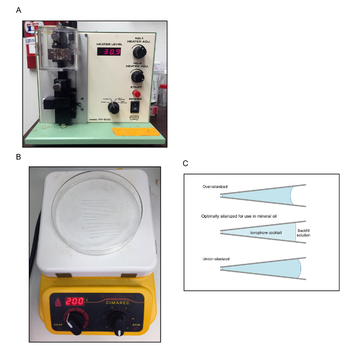
Figure 5. Silanizing Pipets. (A) Example of pipet puller. (B) Picture of the pulled pipets on the hot plate. The glass dish containing a drop of dichlorodimethylsilane has been inverted over the pulled pipets. (C) Schematic illustrating the interface between the ionophore cocktail and the backfill solution. A flat interface indicates optimal silanization. Please click here to view a larger version of this figure.
6. Preparing the Negative Suction Device
Note: In this step, a simple negative suction device is prepared (Figure 6) that will be used to fill the ion-specific electrode. This step is performed only once.
- Attach a 3 ml syringe to a 3 way stopcock with luer lock. At the opposite end of the stopcock, containing the rotating collar and guard, screw in a female locking luer connector with barbed end. Then, attach silicone tubing, 1/16 inch inner diameter with 1/8 inch outer diameter, to the barbed end of the connector. Then, insert plastic tubing with 1/32 inch inner diameter and 3/32 inch outer diameter
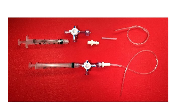
Figure 6. The Negative Suction Device. Picture of the components of the negative suction device (3 ml syringe with luer lock, 3-way stopcock with rotating collar and guard, female luer locking connector with barbed end, silicone tubing, plastic tubing) and the final product. Please click here to view a larger version of this figure.
7. Collect Flies for Dissection
- Use standard fly husbandry techniques25 to set up fly crosses and modify as needed. For example, use increased temperature (such as 28 °C) in experiments where increased GAL4 activity is desired.
Note: It is important that the flies are not reared in overly crowded conditions; the numbers of male and female parents should be decreased in this case. If different genotypes are used, the numbers of male and female parents should be adjusted to obtain approximately similar number of progeny. - Collect flies for dissection (step 11) using standard fly husbandry techniques25 within 1 - 2 days of eclosion. Tubules from female flies are more easily dissected, but tubules from male flies can also be used if necessary or desired. Place flies into a vial containing fly food. Place vials at the desired temperature for 3 - 5 days prior to dissection.
8. Filling the Ion-specific Electrode (ISE)
Note: In this step, the ISE is backfilled with a salt solution and then ionophore is introduced into the tip. The ISE can be re-used from day to day as long as it is working well. Therefore, this step is performed every few days as needed.
- To make a K+-specific electrode, backfill a silanized pipet with 0.5 M KCl using a 1 ml syringe and microfilament (re-use microfilaments from experiment to experiment). Ensure that the backfill solution fills to the very tip of the pipet – no air in tip. If uncertain, visualize under a compound microscope. Dislodge air bubbles by gently flicking the pipet.
- For a Na+-specific electrode, backfill with 150 mM NaCl.
- Insert the back end of the ISE into the plastic tubing of the negative suction device prepared in step 6. In the hood, place the ISE onto an inverted plastic 3.5 cm petri dish with a piece of modeling clay to secure in place.
- Generate negative pressure using the suction device. Draw back on the syringe with the “off” of the stopcock handle pointing toward the side port. The amount of drawing back will vary but is usually in the range of 0.6 – 0.7 ml. Then turn the stopcock handle so the “off” is pointing toward the tubing.
- In the hood and using appropriate personal protective equipment, dip a 1 – 10 µl pipet tip into the ionophore solution (CAUTION: toxic. See Material Data Safety Sheet for safe storage and handling instructions). Expel a small drop by placing a gloved finger over the larger opening of the pipet tip. Then, touch the drop of ionophore to the tip of the ISE, without touching the ISE tip with the pipet tip to avoid breaking the ISE tip.
- Use the potassium ionophore listed in the Materials Table “as is.” To prepare the sodium ionophore, make a solution of (in % w/w) 10% 4-tert-butylcalix[4]arene-tetraacetic acid tetraethylester, 89.75% nitrophenyl octyl ether, and 0.25% sodium tetraphenyl borate (CAUTION: toxic. See Material Data Safety Sheet for safe storage and handling instructions). Store in a glass vial wrapped in foil to shield from light.
- Examine the ISE under 40X magnification using a compound microscope to determine whether the ionophore was “taken up” into the ISE tip and whether the ionophore/backfill solution interface is flat (see step 5.10.1 and Figure 5C).
- If no ionophore was taken up, increase the amount of negative pressure generated by the suction device. If this is not successful, the electrode may have been inadequately silanized. Repeat step 5 using a larger amount of dichlorodimethylsilane.
- Place the ISE, tip down, onto the wall of a beaker partially filled with 150 mM KCl. Secure the ISE by placing modeling clay onto the side of the beaker. The tip lies within the 150 mM KCl. Continue to use the ISE over multiple days as long as it is working well (see step 10.6).
- For a Na+ ISE, store the electrode in 150 mM NaCl.
9. Prepare the Reference Electrode
Note: Steps 9.1 - 9.3 can be performed in advance. Steps 9.4 - 9.6 are performed each experimental day.
- Flame-polish the ends of 10 filamented borosilicate glass capillary tubes (outer diameter 1.2 mm, inner diameter 0.69 mm, length 10 cm) over a low flame, using safety precautions.
- On a pipet puller, pull pipets to a tip diameter of ~1 - 2 µm.
- Store pipets in a pipet storage jar until use. Pipets can be stored indefinitely.
- On the day of the experiment, using a microfilament and syringe, fill the tip and shank of the pipet with 1 M sodium acetate. Ensure there are no air bubbles and that solution goes to the tip. Gently flick the pipet if air bubbles are present.
- Using a second microfilament and syringe, backfill the pipet with 3 M KCl. Again, ensure air bubbles are not present.
- Store the reference electrode in a beaker containing 150 mM KCl (see step 8.6).
10. Calibration of ISE
Note: This step is performed three times on the experiment day: early in the day to make sure the ISE is working, and then before and after measurements of the 20 - 25 secreted fluid drops (Table 3).
- For calibration of the potassium ISE, place two 0.6 µl drops each of the following four concentrations of KCl onto the silicone elastomer-coated 3.5 cm petri dish (prepared in step 1): 15 mM, 75 mM, 150 mM and 200 mM. Carefully layer 2 ml of mineral oil over the drops.
- For sodium ISE, use calibration drops of 15 mM and 150 mM NaCl.
- Place the calibration dish onto the stage of the stereomicroscope in the Faraday cage and illuminate.
- Thread the ISE and reference electrode over the silver wires and fasten into microelectrode holders.
- Using the micromanipulators, advance the ISE and reference electrodes into the 15 mM KCl drop.
- Switch the electrometer to “operate” mode. Allow reading to settle.
- Record reading in notebook. Repeat with the 75 mM, 150 mM and 200 mM drops. Calculate slope to determine whether ISE is working well (see step 13.1 and Table 3). If not, prepare a new ISE.
Note: Signs that an ISE is not working well: failure to get a reading; slow to equilibrate (several seconds or longer); unstable reading; slope <49 mV/decile change in K+ or Na+ concentration. - Between the first calibration of the day and the measurements performed in step 12, ie during the performance of step 11 (tubule dissections), store the ISE and reference electrodes in 150 mM KCl (as described in step 8.6).
11. Tubule Dissection
Note: This step is performed on the experiment day.
- Aliquot out a small amount (~500 - 600 µl) of standard bathing medium (SBM), prepared in step 4.2, for use on the day of experiment and allow to warm to RT. This should be done at least 30 min prior to dissections but can also be done earlier. Also, have at least 20 ml of RT Drosophila saline (step 4.1) available prior to starting dissections.
- Immediately prior to starting dissections: view the assay dish at 10x magnification under a stereomicroscope and add enough SBM to almost fill each well in the assay dish, typically between 10 and 30 μl. If drugs or peptide are going to be added to SBM mid-experiment, make a note of the exact volume of SBM added to each well. Avoid over-filling the well as this can lead to the tubule floating away during the experiment.
- Carefully layer ~12 - 13 ml of mineral oil on top so that the wells are covered. This will prevent evaporation of the secreted fluid drops during the experiment.
- Place flies to be dissected on CO2 pad.
- Pick up a fly via its leg or wing with a forceps and place on its back (ventral side up) on the silicone elastomer-coated dissecting dish prepared in step 1. Impale the thorax with a Minutien pin to secure the fly in place.
- Add a drop of RT Drosophila saline (step 4.1) to immerse the fly in saline.
- Optional: clip off wings and legs. In practice, this is not usually necessary.
- Use the non-dominant hand forceps to “hold” the fly’s abdomen at the thoraco-abdominal junction. Use the dominant hand forceps to peel the abdominal cuticle away, starting at the thoraco-abdominal junction and moving towards the tail end of the fly. The gut, with attached Malpighian tubules, should be exposed with this maneuver.
- Without touching the tubules, dissect free the midgut/hindgut and attached tubules. Hold the gut in the non-dominant hand forceps and use a 30 G needle to sever the ureter from the gut, detaching the tubules from the gut and free from the fly.It is essential that no tears or rents be introduced into the tubule, other than at the ureter.
Note: The anterior pair of tubules is most easily dissected, however the posterior tubules may be used as well. - Using the fine glass rod (step 2), pick up the tubule pair and transfer into a well of the assay dish.
- Immediately after the tubule pair has been transferred into the well, pick up the end of one of the tubules with the glass rod, withdraw from the bathing drop until the cut end of the ureter is halfway between the pin and the bathing drop, and wrap the end of the tubule around the pin using the glass rod. At the end of this maneuver, one tubule remains in the bathing saline drop and will secrete fluid from the cut end of the ureter, as illustrated in Figure 1. The other tubule, labeled the “anchor tubule” in Figure 1, is wrapped around the pin. It anchors the secreting tubule in place, is surrounded by oil, and does not secrete fluid.
- Immediately after step 11.11, write down the well (e.g., A, B, C), tubule identifying information (e.g., genotype or condition), and the time (this is the start time when fluid will begin to be secreted by the tubule in the droplet of bathing saline).
- Proceed with the next dissection. Once the experimenter is skilled in this technique, it typically takes 3 - 4 min to dissect a pair of tubules, transfer them to the bathing saline, and wrap the anchor tubule around the pin. Therefore, 20 - 25 tubules can be set up in the Ramsay assay within 1.5 hr. The start time of each tubule will therefore be about 3 - 4 min after the start time of the previous tubule.
12. Making Measurements
Note: This step is performed on the experiment day.
- Calibrate the ISE (step 10) approximately 20 min before the first measurement. This allows time to make a new ISE if needed.
Note: At the desired time, for example after 2 hr of secretion, the secreted fluid drop of each tubule is ready for measurement. - Record the time of measurement. Measure the diameter of the secreted fluid drop using the ocular micrometer and record. Note the magnification, e.g., 50X.
- Advance the ISE and reference electrode into the fluid drop. Switch the electrometer to “operate.” Allow the reading to stabilize. Record the value.
- Repeat for the next drop.
- At the end of the experiment, repeat the calibration measurements (step 10).
13. Calculations
Note: This step can be performed either at the end of the experiment day, or at a later time.
- Calculate the mean slope/decile change in potassium concentration. See Table 3 for an example.
Note: For sodium, the values will be for the difference between the 15 mM and 150 mM NaCl measurements. - Determine the mean value of the two measurements (before and after) of 200 mM KCl (or 150 mM NaCl).
- Calculate the volume of each droplet. V = πd3/6, where d is the diameter of the droplet measured with the ocular micrometer in step 12.2.
- Calculate the secretion rate = V/time (nL/min/tubule), where V is the volume of the droplet determined in step 13.3, and time is the length of time the tubule secreted fluid (= time of measurement - time of pulling ureter out of bathing droplet).
- Calculate the ion concentration using the formula [K] = 10e(Δv/S)*200 or [Na] = 10e(Δv/S)*150, where Δv = the difference (in mV) between the potential measured of the secreted fluid drop, and the potential of the 200 mM calibration drop (for potassium; 150 mM drop for sodium). S = the slope determined in step 13.1.
- Calculate ion flux = [ion] x fluid secretion rate. For Drosophila tubules, this will be pmol/min/tubule.
14. Cleaning Up
Note: This step is performed at the end of the experiment day.
- Thorough cleaning of the wells is essential to ensure that residual salt crystals do not remain in the wells, altering the ion concentration and osmolarity in future experiments.
- Allow the mineral oil to drain off.
- Rinse the wells of the assay dish. A 200 μl pipet tip can be used to gently scrape off residual salt crystal. Using plastic tubing attached to the faucet, squeeze the tubing to create a high-pressure jet of hot water to thoroughly rinse out each well.
- Allow to dry O/N. Alternatively, a blow dryer can be used to dry out the wells.
- Rinse off forceps with deionized H2O and soak in ethanol for 15 min to several hours.
- Drain oil off of calibration dish and wash with hot water. Use soap as well as long as it is thoroughly rinsed off. Perform the final rinse with distilled H2O.
- Flush microfilaments and syringes with distilled H2O.
Access restricted. Please log in or start a trial to view this content.
Results
Figures 7 and 8 demonstrate that use of the Ramsay assay with ion-specific electrodes to measure K+ and Na+ concentrations can distinguish genetically and pharmacologically distinct K+ and Na+ fluxes, information that is not captured by measuring fluid secretion rates alone. Figure 7 shows that decreased fluid secretion in tubules from flies carrying a homozygous null mutation in the NKCC is driven by a decrease in K+ flux in the mut...
Access restricted. Please log in or start a trial to view this content.
Discussion
The use of the Ramsay assay, together with ion-specific electrodes, allows the measurement of fluid secretion rates and ion fluxes in isolated insect Malpighian (renal) tubules. Twenty or more tubules can be assayed at a time, allowing higher throughput compared to the assay of individual in vitro microperfused tubules. In addition, ion-specific electrodes allow the determination of ion concentrations within the secreted fluid in situ, limiting errors that may be introduced in the transfer of the small ...
Access restricted. Please log in or start a trial to view this content.
Disclosures
The authors have nothing to disclose.
Acknowledgements
The authors wish to thank Drs. Sung-wan An and Mike O’Donnell for practical advice on establishing this assay, Dr. Chih-Jen Cheng for helpful discussions on the use of ion-specific electrodes, and Dr. Chou-Long Huang for his mentorship and support. This work was supported by the National Institutes of Health (K08DK091316 to ARR) and the American Society of Nephrology Gottschalk Award to ARR.
Access restricted. Please log in or start a trial to view this content.
Materials
| Name | Company | Catalog Number | Comments |
|---|---|---|---|
| Sylgard 184 Silicone Elastomer Kit | Ellsworth Adhesives | http://www.ellsworth.com/dow-corning-sylgard-184-silicone-encapsulant-0-5kg-kit-clear/ | May be purchased from multiple distributors |
| Petri dish, polystyrene, 100 mm x 15 mm | Fisher | FB0875712 | Specific brand is not important |
| Petri dish, polystyrene, 35 mm x 10 mm | Corning Life Sciences | Fisher 08-757-100A | Specific brand is not important |
| Scalpel Handle #3 | Fine Science Tools | 10003-12 | Specific brand is not important |
| Scalpel Blades #1 | Fine Science Tools | 10011-00 | Specific brand is not important; use appropriate sharps precautions |
| Needle, 30 G x 1/2 | Becton Dickinson | 305106 | Use appropriate sharps precautions |
| Minutien pins, black anodized, 0.15 mm | Fine Science Tools | 26002-15 | |
| Stereomicroscope with ocular micrometer | Nikon | SMZ800 | Specific brand is not important; this is given as an example |
| Sheet of black stained glass, 3 mm (1/8 inch) thick | Hobby shop | Example includes Spectrum Black Opal by Spectrum Glass (http://www.delphiglass.com/spectrum-glass/opalescent/spectrum-black-opal) | |
| Glass cutting tools (glass cutter, glass cutting pliers) | Hobby shop | Examples include the Studio Pro Lightweight Running Pliers by Diamond Tech (http://www.delphiglass.com/glass-cutters-tools/pliers-nippers/studio-pro-lightweight-running-pliers) and the Studio Pro Brass Glass Cutter by Diamond Tech (http://www.delphiglass.com/glass-cutters-tools/glass-cutters/studio-pro-brass-glass-cutter). Use appropriate safety precautions when cutting glass | |
| Borosilicate glass capillary tube, unfilamented, GC120-10, OD 1.2 mm, ID 0.69 mm, length 10 cm | Warner Instruments | 30-0042 | |
| Borosilicate glass capillary tube, filamented, GC120F-10, OD 1.2 mm, ID 0.69 mm, length 10 cm | Warner Instruments | 30-0044 | |
| Nitric acid, 70% | Sigma | 438073 | CAUTION: see Material Data Safety Sheet for appropriate storage and handling guidelines. Specific brand is not important |
| Cimarec 7 in x 7 in hotplate | Fisher | 11675911Q | Specific brand is not important; caution when heated |
| Selectophore dichlorodimethylsilane | Sigma | 40136-1ML | CAUTION: see Material Data Safety Sheet for appropriate storage and handling guidelines |
| Two-step vertical pipet puller | Narishige | PC-10 | Other pipet pullers can be used; this is given as an example |
| Glass petri dish, 150 mm diameter x 15 mm height | Fisher | 08-748E | Specific brand is not important; only one dish needed |
| World Precision Instruments E210 1 mm micropipette storage jar | Fisher | 50-821-852 | May be available from other distributors. Useful to have two jars. Note that although this jar is specified for 1 mm pipets, and the pipets used here are 1.2 mm, in our experience the 1 mm jar works best for the 1.2 mm pipets. |
| Silica Gel, Tel-Tale Desiccant, indicating, 10-18 mesh | Fisher | S161-500 | Indicating silica useful for determining whether silica gel retains desiccating ability |
| World Precision Instruments MicroFil, 34G | Fisher | 50-821-914 | May be available from other distributors. |
| 1 ml syringe with luer lock | Becton Dickinson | 309659 | May be available from other distributors. |
| 3 ml syringe with luer lock | Becton Dickinson | 309657 | May be available from other distributors. |
| D300 3-way stopcock with female luer lock inlet port, male luer outlet port with rotating collar and guard | Cole-Parmer | UX-30600-02 | Specific brand is not important |
| Female Luer Locking Connector | 4 Medical Solutions | ADC 9873-10 | Specific brand is not important; barbed end is ~4 mm at narrowest point and ~7 mm at widest point. |
| Silicone Tubing I.D. x O.D. x Wall: 1/16 x 1/8 x 1/32 in. (1.59 x 3.18 x 0.79 mm) | Fisher | 14-179-110 | Specific brand is not important |
| E-3603 tubing, I.D. x O.D.: 1/32 x 3/32 in | Fisher | 14171208 | Specific brand is not important |
| Modeling clay | Specific brand is not important | ||
| Selectophore potassium ionophore I, cocktail B | Sigma | 99373 | CAUTION: see Material Data Safety Sheet for appropriate storage and handling guidelines |
| Selectophore sodium ionophore X | Sigma | 71747 | Sodium ionophore X = 4-tert-butylcalix[4]arene-tetraacetic acid tetraethylester |
| Selectophore 2-nitrophenyl octyl ether | Sigma | 73732 | |
| Selectophore sodium tetraphenylborate | Sigma | 72018 | CAUTION: see Material Data Safety Sheet for appropriate storage and handling guidelines |
| Schneider's Drosophila medium | Life Technologies | 21720024 | |
| High impedance electrometer | World Precision Instruments | FD223a | |
| Microelectrode holder 1 mm with 45° body, vented, with handle | Warner Instruments | 64-1051 | |
| Microelectrode holder 1 mm with straight body, vented | Warner Instruments | 64-1007 | |
| Silver wire | Warner Instruments | 64-1318 | |
| Micromanipulators, pair | Leitz | Various brands/models will work; this is an example | |
| Faraday cage | Technical Manufacturing Corporation | 81-334-03 | This is an example; any Faraday cage will work |
| Single gooseneck fiberoptic light | Nikon | Specific brand is not important | |
| mineral oil | Fisher | BP-2629 | Specific brand is not important |
| forceps, Dumont #5 with Biologie tip | Fine Science Tool | 11295-10 | May be available from other distributors. |
References
- Ramsay, J. A. Active Transport of Water by the Malpighian Tubules of the Stick Insect, Dixippus-Morosus (Orthoptera, Phasmidae). J Exp Biol. 31, 104-113 (1954).
- Dow, J. A., et al. The malpighian tubules of Drosophila melanogaster: a novel phenotype for studies of fluid secretion and its control. J Exp Biol. 197, 421-428 (1994).
- Brand, A. H., Perrimon, N. Targeted gene expression as a means of altering cell fates and generating dominant phenotypes. Development. 118, 401-415 (1993).
- Sozen, M. A., Armstrong, J. D., Yang, M., Kaiser, K., Dow, J. A. Functional domains are specified to single-cell resolution in a Drosophila epithelium. Proc Natl Acad Sci U S A. 94, 5207-5212 (1997).
- Rosay, P., et al. Cell-type specific calcium signalling in a Drosophila epithelium. J Cell Sci. 110 (15), 1683-1692 (1997).
- Dow, J. T., Davies, S. A. Integrative physiology and functional genomics of epithelial function in a genetic model organism. Physiol Rev. 83, 687-729 (2003).
- Beyenbach, K. W., Skaer, H., Dow, J. A. The developmental, molecular, and transport biology of Malpighian tubules. Annu Rev Entomol. 55, 351-374 (2010).
- Donnell, M. J., et al. Hormonally controlled chloride movement across Drosophila tubules is via ion channels in stellate cells. Am J Physiol. 274, 1039-1049 (1998).
- Linton, S. M., O'Donnell, M. J. Contributions of K+:Cl- cotransport and Na+/K+-ATPase to basolateral ion transport in malpighian tubules of Drosophila melanogaster. J Exp Biol. 202, 1561-1570 (1999).
- Rheault, M. R., O'Donnell, M. J. Analysis of epithelial K(+) transport in Malpighian tubules of Drosophila melanogaster: evidence for spatial and temporal heterogeneity. J Exp Biol. 204, 2289-2299 (2001).
- Donnell, M. J., Dow, J. A., Huesmann, G. R., Tublitz, N. J., Maddrell, S. H. Separate control of anion and cation transport in malpighian tubules of Drosophila Melanogaster. J Exp Biol. 199, 1163-1175 (1996).
- Cabrero, P., et al. Chloride channels in stellate cells are essential for uniquely high secretion rates in neuropeptide-stimulated Drosophila diuresis. Proc Natl Acad Sci U S A. 111, 14301-14306 (2014).
- Torrie, L. S., et al. Resolution of the insect ouabain paradox. Proc Natl Acad Sci U S A. 101, 13689-13693 (2004).
- Rodan, A. R., Baum, M., Huang, C. L. The Drosophila NKCC Ncc69 is required for normal renal tubule function. Am J Physiol Cell Physiol. 303, 883-894 (2012).
- Ianowski, J. P., Christensen, R. J., O'Donnell, M. J. Na+ competes with K+ in bumetanide-sensitive transport by Malpighian tubules of Rhodnius prolixus. J Exp Biol. 207, 3707-3716 (2004).
- Naikkhwah, W., O'Donnell, M. J. Salt stress alters fluid and ion transport by Malpighian tubules of Drosophila melanogaster: evidence for phenotypic plasticity. J Exp Biol. 214, 3443-3454 (2011).
- Donini, A., et al. Secretion of water and ions by malpighian tubules of larval mosquitoes: effects of diuretic factors, second messengers, and salinity. Physiol Biochem Zool. 79, 645-655 (2006).
- Maddrell, S. H. Secretion by Malpighian Tubules of Rhodnius movements of Ions and Water. J Exp Biol. 51, 71-97 (1969).
- Maddrell, S. H., Overton, J. A. Stimulation of sodium transport and fluid secretion by ouabain in an insect malpighian tubule. J Exp Biol. 137, 265-276 (1988).
- Williams, J. C., Beyenbach, K. W. Differential effects of secretagogues on Na and K secretion in the Malpighian tubules of Aedes Aegypti (L). J Comp Physiol. 149, 511-517 (1983).
- Maddrell, S. H., O'Donnell, M. J., Caffrey, R. The regulation of haemolymph potassium activity during initiation and maintenance of diuresis in fed Rhodnius prolixus. J Exp Biol. 177, 273-285 (1993).
- Messerli, M. A., Kurtz, I., Smith, P. J. Characterization of optimized Na+ and Cl- liquid membranes for use with extracellular, self-referencing microelectrodes. Anal Bioanal Chem. 390, 1355-1359 (2008).
- Ianowski, J. P., O'Donnell, M. J. Basolateral ion transport mechanisms during fluid secretion by Drosophila Malpighian tubules: Na+ recycling, Na+:K+:2Cl- cotransport and Cl- conductance. J Exp Biol. 207, 2599-2609 (2004).
- Neufeld, D. S., Leader, J. P. Electrochemical characteristics of ion secretion in malpighian tubules of the New Zealand alpine weta (Hemideina maori). J Insect Physiol. 44, 39-48 (1997).
- Greenspan, R. J. Fly Pushing: The Theory and Practice of Drosophila Genetics. , Cold Spring Harbor Laboratory Press. (1997).
- Jayakannan, M., Babourina, O., Rengel, Z. Improved measurements of Na+ fluxes in plants using calixarene-based microelectrodes. J Plant Physiol. 168, 1045-1051 (2011).
- Wu, Y., Schellinger, J. N., Huang, C. L., Rodan, A. R. Hypotonicity Stimulates Potassium Flux through the WNK-SPAK/OSR1 Kinase Cascade and the Ncc69 Sodium-Potassium-2-Chloride Cotransporter in the Drosophila Renal Tubule. J Biol Chem. 289, 26131-26142 (2014).
- Blumenthal, E. M. Modulation of tyramine signaling by osmolality in an insect secretory epithelium. Am J Physiol Cell Physiol. 289, 1261-1267 (2005).
- Dow, J. A., Maddrell, S. H., Davies, S. A., Skaer, N. J., Kaiser, K. A novel role for the nitric oxide-cGMP signaling pathway: the control of epithelial function in Drosophila. Am J Physiol. 266, 1716-1719 (1994).
- Dube, K., McDonald, D. G., O'Donnell, M. J. Calcium transport by isolated anterior and posterior Malpighian tubules of Drosophila melanogaster: roles of sequestration and secretion. J Insect Physiol. 46, 1449-1460 (2000).
- Efetova, M., et al. Separate roles of PKA and EPAC in renal function unraveled by the optogenetic control of cAMP levels in vivo. J Cell Sci. 126, 778-788 (2013).
- Rheault, M. R., O'Donnell, M. J. Organic cation transport by Malpighian tubules of Drosophila melanogaster: application of two novel electrophysiological methods. J Exp Biol. 207, 2173-2184 (2004).
- Donnell, M. J. Too much of a good thing: how insects cope with excess ions or toxins in the diet. J Exp Biol. 212, 363-372 (2009).
- Cheng, C. J., Truong, T., Baum, M., Huang, C. L. Kidney-specific WNK1 inhibits sodium reabsorption in the cortical thick ascending limb. Am J Physiol Renal Physiol. 303, 667-673 (2012).
- Cheng, C. J., Yoon, J., Baum, M., Huang, C. L. STE20/SPS1-related Proline/alanine-rich Kinase (SPAK) is Critical for Sodium Reabsorption in Isolated Perfused Thick Ascending Limb. Am J Physiol Renal Physiol. , (2014).
Access restricted. Please log in or start a trial to view this content.
Reprints and Permissions
