

Summary
This protocol describes a rod-based approach, combining 3D-printing and soft lithography techniques for fabricating the soft gripper devices. This approach eliminates the need for an external air source by incorporating a chamber component and reduces the chance of occlusion during the sealing process, particularly for miniaturized pneumatic channels.
Abstract
Soft compliant gripping is essential in delicate surgical manipulation for minimizing the risk of tissue grip damage caused by high stress concentrations at the point of contact. It can be achieved by complementing traditional rigid grippers with soft robotic pneumatic gripper devices. This manuscript describes a rod-based approach that combined both 3D-printing and a modified soft lithography technique to fabricate the soft pneumatic gripper. In brief, the pneumatic featureless mold with chamber component is 3D-printed and the rods were used to create the pneumatic channels that connect to the chamber. This protocol eliminates the risk of channels occluding during the sealing process and the need for external air source or related control circuit. The soft gripper consists of a chamber filled with air, and one or more gripper arms with a pneumatic channel in each arm connected to the chamber. The pneumatic channel is positioned close to the outer wall to create different stiffness in the gripper arm. Upon compression of the chamber which generates pressure on the pneumatic channel, the gripper arm will bend inward to form a close grip posture because the outer wall area is more compliant. The soft gripper can be inserted into a 3D-printed handling tool with two different control modes for chamber compression: manual gripper mode with a movable piston, and robotic gripper mode with a linear actuator. The double-arm gripper with two actuatable arms was able to pick up objects of sizes up to 2 mm and yet generate lower compressive forces as compared to elastomer-coated and non-coated rigid grippers. The feasibility of having other designs, such as single-arm or hook gripper, was also demonstrated, which further highlighted the customizability of the soft gripper device, and it's potential to be used in delicate surgical manipulation to reduce the risk of tissue grip damage.
Introduction
Soft robots have sparked great research interest within the robotics community and they have been used in different functional tasks such as undulatory locomotion in unstructured environments1 and gripping2. They are mainly composed of soft elastomeric materials and controlled by different actuation techniques through the use of different materials such as electroactive polymer (EAP), shape memory alloy (SMA), or compressed fluid3. EAPs function based on a differential voltage that induces electrostatic forces to produce active strains and thereby generates actuation. The peculiar shape memory effect of the SMAs is deployed to generate the desired actuation based on the force generation during phase transformations upon the change in temperature. Lastly, compressed fluid actuation technique facilitates a simple design strategy to induce stiffness difference in the soft actuators, such that the more compliant regions will inflate upon pressurization. Soft robots are designed to broaden the applications of traditional hard robots, especially in applications where delicate objects are involved. Particularly, in this paper, we present our unique approach in developing soft robotic grippers for delicate surgical manipulation.
Surgical gripping is an important aspect involved in many surgical procedures such as hepatic, gynecological, urological, and nerve repair surgeries4, 5. It is typically performed by rigid, steel tissue gripping tools such as the forceps and laparoscopic graspers for the purpose of facilitating observation, excision, anastomosis procedures, etc. However, extreme caution is required as the conventional gripping tools are made of metal that may cause high stress concentration areas in the soft tissue at the points of contact6. Depending on the severity of the tissue damages, various complications, such as pain, pathological scar tissue formation, and even permanent disability, may result. A prior study reported that the complication rate in peripheral nerve surgery was 3%7. Therefore, the concept of soft gripping that can provide safe compliant grip can be a promising candidate for delicate surgical manipulation.
Here, we present a combination of 3D-printing and modified soft lithography techniques, which adopted a rod-based approach, to fabricate customizable soft robotic pneumatic grippers. Traditional fabrication technique of soft robots based on compressed fluid actuation requires a mold with pneumatic channels printed on it and a sealing process to seal the channels8. However, it is not feasible for miniaturized soft robots which need small pneumatic channels where occlusion of channels can easily happen in the sealing process. The traditional technique requires the sealing of the pneumatic channels to be done by bonding a coated sealing layer to it. Hence, the layer of elastomeric material which initially serves as a bonding layer may spill into the tiny channels and occlude those channels. It is also not possible to position the pneumatic channels at the middle of the structure and connect to a chamber component using conventional techniques. The proposed approach allows the creation of miniaturized pneumatic channels connected to an air-filled chamber using rods and does not require sealing of the tiny channels. In addition, the chamber connected to the pneumatic channels serve as an air source which does not require external air sources for compressed fluid actuation. It allows both the manual and robotic control modes by facilitating the chamber compression to actuate the gripping component, thereby providing users the option of controlling the amount of force that they are applying through the gripper. This approach is highly customizable and can be used to fabricate various types of soft gripper designs such as grippers with single or multiple actuatable arms.
Subscription Required. Please recommend JoVE to your librarian.
Protocol
Note: All the soft pneumatic grippers were fabricated by casting silicone-based elastomeric mixtures into customized 3D-printed molds, which followed a fabrication process comprising three steps: molding gripper-arm components with embedded pneumatic channels, molding chamber component connected to the pneumatic channels, and sealing the chamber component filled with air.
1. Preparation of Elastomers
- Place a container for mixer on a weighing scale and tare it. Pour parts A and B of the silicone-based elastomer in the container with a 1:1 weight ratio.
- Cover the container and measure the total weight.
- Place the container and material into a centrifugal mixer. Adjust the weight balance on the mixer to the weight measured in step 1.2.
- Set the mixing and de-aeration modes to 2,000 rpm and 2,200 rpm respectively for 30 sec. Mix the elastomer components thoroughly to achieve uniform curing.
2. Mold Design and Production
Note: The geometry of the mold will vary depending on the specific requirements for different applications. The following steps illustrate general key steps in CAD software that are required to create the chamber and gripper component of the mold.
- Design the molds and sealing mold using computer-aided design (CAD) software. See Figure 1 for the geometry and specific dimensions of the molds used in this manuscript.
- Design of the outer boundary box
- Right-click on the top plane and click on "Normal to" button to normalize to the top plane.
- Click on "Sketch" on the top left corner to open a "Sketch" window. Then, click on the "Sketch" button on the top left corner of the toolbar to draw a rectangular base of chamber component.
- Click on the "Smart Dimension" feature, which is located beside the "Sketch" button, to define sketch dimensions. Ensure that the sketch is fully defined (i.e., all drawing lines become black) and exit the sketch when done.
- Click on the "Features" window. Then, click on "Extruded Boss/Base" feature to extrude selected contours in the Y-direction.
- Click on the top surface of the model to preselect the sketch plane. Sketch a rectangle and define the dimensions as described in 2.1.1.2 and 2.1.1.3.
- Click on the "Features" window. Then, click on "Extruded Cut" feature to extrude cut a cavity for casting elastomers (Figure 2A). Ensure that the wall thickness is 2.5 mm.
- Design of the inner chamber
- Right-click on the surface on the Y-direction of the opening area. Then, click on "Normal to" to normalize to that surface.
- Next, click on the "Sketch" window to draw a rectangle for chamber component as described in steps 2.1.1.2 and 2.1.1.3.
- Click on the "Features" window. Then, click on "Extruded Boss/Base" feature to extrude the chamber component in the Y-direction (Figure 2B).
Note: The depth of the cut in step 2.1.1.6 is 2.5 mm larger than this extruded base.
- Design of the gripper component
- Click on the surface of the model in negative X-direction to preselect the sketch plane for gripper component. Create a rectangle in the "Sketch" window as described in steps 2.1.1.2 and 2.1.1.3.
- Click on the "Features" window. Then, click on "Extruded Boss/Base" feature to extrude the selected contour in the negative X-direction.
- Click on the top surface of the gripper component to preselect the sketch plane. Create a shape of gripper in the "Sketch" window (Figure 2C) and exit the sketch when the dimensions is fully defined as described in steps 2.1.1.2 and 2.1.1.3.
- Click on the "Features" window. Then, click on "Extruded Cut" to cut a cavity for casting elastomers in the gripper component. Ensure that the wall thickness is 2.5 mm.
- Design of the connection between chamber and gripper
- Create a rectangle in the "Sketch" window on the top surface of the chamber piece as described in 2.1.1.2 and 2.1.1.3.
- Click on the "Features" window. Then, click on "Extruded Cut" to create a connection between chamber and gripper components (Figure 2D).
- Design of the pneumatic channels
- Create 1.5 mm diameter circles on the surface of the chamber piece in the positive X-direction as described in steps 2.1.1.2 and 2.1.1.3.
- Click on the "Features" window. Then, click on "Extruded Cut" to create channels for wire rods insertion (Figure 2E). Ensure the holes are not cut through the gripper component.
- Design of the outer boundary box
- In a separate CAD file, draw a sealing mold with a cavity of length and width that are 1 mm larger than the outer dimensions of the chamber component of the gripper. Note: The wall thickness is 2.5 mm.
- Click on the "Sketch" window to create a rectangle on the top plane as described steps 2.1.1.2 and 2.1.1.3.
- Click on the "Features" window. Then, click on "Extruded Boss/Base" feature to extrude selected contours in the Y-direction.
- Click on the top face of the model to preselect the sketch plane. Sketch a rectangle and define the dimensions as described in steps 2.1.1.2 and 2.1.1.3).
- Click on the "Features" window. Then, click on "Extruded Cut" feature to extrude cut a cavity for casting elastomers. Ensure that the wall thickness is 2.5 mm.
- Save each mold piece as a .STL file for 3D printing.
- Load the .STL file into the 3D printer with resolution of 30 µm and print the mold pieces9.
- Remove any support material on the mold pieces and wash the mold pieces with water.
3. Soft Single/Double-actuatable Arm Pneumatic Grippers
- Molding gripper-arm components with embedded pneumatic channels
- Insert two 3D-printed chamber-blocks on the left and right side of the chamber component (Figure 3A) in order to generate a sealed chamber with pneumatic channels connected to it.
- Insert two 1.5 mm-diameter titanium wire rods through the chamber, keeping a 2 mm distance from the gripper tips to create the pneumatic channels (Figure 3A). Note: Use one wire rod for the single-actuatable-arm gripper.
- Pour the elastomeric mixture into the mold to fully fill the gripper component.
- Ensure there is no visible air bubbles present.
- Place the mold into oven for curing at 60 °C for 10 min. Once elastomer is cured, remove the mold from the oven.
- Molding chamber component connected to the pneumatic channels
- Pull the wire rods and the two chamber-blocks out from the mold.
- Place a 3D-printed gripper-block on top of the gripper component in order to create the chamber (Figure 3B). Insert the wire rods to block the holes in the wall of the mold.
- Pour the elastomeric mixture into the mold to fill the remaining part of chamber component and ensure there is no visible air bubbles trapped in the mold.
- Cure the part at a temperature of 60 °C for 10 min. Remove the mold from the oven once elastomer is cured.
- Remove the gripper-block and demold the fully cured gripper with chamber structure.
- Sealing the chamber component filled with air
- Pour the elastomeric mixture into the sealing mold and cure it at 60 °C for 10 min.
- Brush a layer of elastomeric material on the cured 2.5 mm sealing layer. Place the cured gripper with chamber structure on top of the coated sealing layer and bond the two pieces together (Figure 3C).
- Subsequently, cure the entire structure fully at 60 °C for 15 min.
- Demold the fully cured soft robotic gripper device.
4. Insertion of Soft Robotic Pneumatic Gripper Device into Handling Tool
- Design the handling tools as described in the Supplemental file 1 using CAD software and save it in .STL file. See Figures 4 and 5 for the dimensions of the tools.
- Load the .STL file in the 3D printer and print the mold pieces9.
Note: All printing steps for manual control handling tool, rectangular cap, and movable piston (Figure 4) can be completed within 3 hr 48 min. The printing time for fabricating the robotic control handling tool and rectangular cap (Figure 5) is 1 hr 56 min. See Supplemental file 2 for 3D printer operation instructions. - Peel off any support material on the tools after the printing is completed. Then, wash the tools with water.
- Insert the gripper into the manual control handling tool (Figure 4A) and cover the opening area with a movable rectangular cap (Figure 4B).
- Insert a movable piston (Figure 4C) to facilitate chamber compression.
- Insert the gripper and linear actuator into the robotic control handling tool (Figure 5A). Note: The linear actuator replaces the movable piston in manual control mode for chamber compression.
- Cover the opening area with a movable rectangular cap (Figure 5B).
5. Evaluations and Grip Compressive Test
- Evaluate the functionality of the soft gripper by performing gripping tests with a jumper wire.
- Place a jumper wire on the table.
- Adjust the gripper so that the wire is in between of the two gripper arms.
- Move the movable piston to compress the chamber in order to actuate the gripper arms to hold the wire.
Note: Only the manual control handling tool is used in the gripping demonstration. - Hold and move the wire to a box located at 20 cm away from wire's original location.
- Place a calibrated force sensing resistor between the two jaws of the gripper. Ensure the gripper jaws grip on the sensing area. Note: The diameter of the sensing area is 14.7 mm.
- Compress the chamber to actuate the gripper arms to grip on the force sensing resistor.
- Measure the maximum grip compressive forces that the soft single-actuatable-arm and double-actuatable-arm pneumatic grippers could generate as described in 10.
Note: The readout values will be displayed on a laptop. The maximum grip compressive forces are measured at the point of maximum pressure that the pneumatic channels can withstand. - Cut out the individual elastomeric gripping jaws from a soft double-actuatable-arm pneumatic gripper.
- Insert the forceps tips into the pneumatic channels of the elastomeric gripping jaws.
- Place a calibrated force sensing resistor between the two jaws of the forceps.
- Measure the compressive forces10 generated by elastomer-coated forceps and forceps during a simulated nerve surgery conducted by a neurosurgeon.
Note: The neurosurgeon applies a force that is similar to what he normally applies during actual surgery on the force sensing resistor. - Average the data obtained from five trials in each test.
Subscription Required. Please recommend JoVE to your librarian.
Representative Results
The soft robotic pneumatic gripper devices were capable of picking up objects with dimensions of up to 1.2 mm in diameter (Figure 6). The maximum grip compressive force generated by the single- actuatable-arm, and double- actuatable-arm soft gripper devices were 0.27 ± 0.07 N and 0.79 ± 0.14 N respectively, as compared to 1.71 ± 0.16 N and 2.61 ± 0.22 N compressive forces in simulated surgery by the elastomer-coated forceps and by uncoated forceps (Figure 7). The grip forces may vary depending on the geometry of the grippers and the size of the pneumatic channels. The elastomer's material properties will determine the maximum pressure that the pneumatic channels can withstand, which in turn will affect the grip forces. The proposed technique (Figure 3) demonstrates that a low-cost creation of soft pneumatic gripper in quick fabrication time is possible, and the functionality of such grippers was evaluated in this study. Using the technique described, fabrication of different gripper designs for various applications can be accomplished by designing corresponding molds for casting the elastomer.
These results showed that compliant gripping, without the introduction of excessive stress to the gripped object, is achievable with the proposed fabrication technique. The adaptability of the soft gripper arms allowed the arms to conform to the surface contour of the object. However, it is necessary to ensure that secure gripping is not compromised when a compliant grip is achieved. A grip that is both the firm and compliant is essential for gripping applications especially in surgery. The outcome can be further analyzed by conducting pilot mouse trials to evaluate the performance of soft gripper in holding the mouse's nerve and to examine the extent of damage made to the nerve when the soft gripper is used as compared to when the forceps are used.

Figure 1. 2D CAD drawings of the molds used for fabricating the top structure of the elastomeric soft robotic pneumatic gripper devices: (A) double-actuatable-arm, and (B) single- actuatable-arm (all dimensions are in mm). The wall thickness is 2.5 mm for all molds. Please click here to view a larger version of this figure.

Figure 2. Creating the mold in CAD. (A) Extrude cut a cavity for casting elastomers. (B) Create a chamber component in the mold. (C) Create a cavity for casting elastomers for gripper component. (D) Extrude cut a connection between chamber and gripper component. (E) Extrude cut two holes for holding the wire rods to create pneumatic channels. Please click here to view a larger version of this figure.

Figure 3. Fabrication process of the soft double-actuatable-arm pneumatic gripper. (A) Place two chamber-blocks and insert two wire rods to create pneumatic channels that are connected to a chamber. Pour elastomer into the mold and fully cure the gripping component. (B) Remove the wire rods and chamber-blocks and put a gripper-block on top of the gripping component to create chamber. Pour elastomer into the mold to make the chamber component. (C) Bond the gripper structure and 2.5 mm layer together to create a sealed air-filled chamber. Please click here to view a larger version of this figure.

Figure 4. 2D CAD drawings of the handling tools for manual control mode to facilitate chamber compression. (A) Handling tool, (B) rectangular cap, and (C) movable piston (all dimensions are in mm and the scale is 2:3 unless specified). Please click here to view a larger version of this figure.
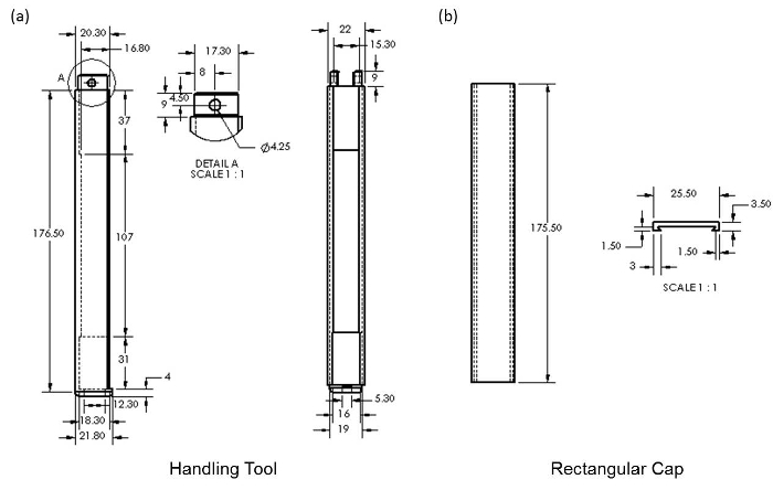
Figure 5. 2D CAD drawings of the handling tools for robotic control mode to facilitate chamber compression. (A) Handling tool, and (B) rectangular cap (all dimensions are in mm and the scale is 2:3 unless specified). Please click here to view a larger version of this figure.

Figure 6. Evaluation of gripping tests of the proposed gripper devices. Photographs of the soft robotic (A) single-actuatable-arm, and (B) double-actuatable-arm pneumatic gripper devices before (left) and upon (right) gripping the 1.2 mm diameter wire.

Figure 7. Grip compressive forces generated by the two different soft robotic pneumatic gripper devices, and the two (elastomer-coated and uncoated) forceps in grip compressive test. A force sensing resistor was placed between the two jaws of the gripper/forceps and the gripper/forceps jaws grip on the sensing area in each test. The error bars represent standard deviation.

Figure 8. 2D CAD drawings of the molds used for fabricating the top structure of the soft robotic hook pneumatic gripper. The pneumatic channel is positioned closer to the bottom surface of the hook gripping component and it will bend upward upon pressurization.
Supplementary file 1. Design of the handling tools. Stepwise details on the design of the handling tools involved in CAD software. Please click here to download this file.
Supplementary file 2. 3D printer user guide. This user guide provides instructions for operating the printer. Please click here to download this file.
Subscription Required. Please recommend JoVE to your librarian.
Discussion
We have successfully demonstrated that the soft robotic pneumatic gripper devices allowed compliant gripping of objects, which exerted much lower compressive forces on the gripped object than the elastomer-coated forceps tips and forceps exerted. Forceps is an essential tool for nerves manipulation during peripheral nerve repair surgeries11, 12. However, its metallic structure required extreme caution in usage from the surgeons in order to prevent nerve damage caused by excessive gripping forces and the incidental damage to the surrounding tissues. Depending on the severity of the damage, various complications ranging from the less severe ones, such as pain, to severe ones, such as blood clots and even permanent disability, may result. Considering the need to prevent incidental damage of nerve tissues during surgical manipulation, our preliminary findings indicate that these soft robotic pneumatic gripper devices are potential suitable candidates for complementing current forceps during delicate tissue manipulation by providing the ability to achieve compliant grip. The silicone-based elastomer used in fabricating the soft gripper has a Young's modulus of 0.8 x 10⁵ Pa, which is comparable to those of soft deformable human muscles and tissues13, 14. Therefore, it will reduce the risks of tissue damage as compared to its counterpart rigid grippers.
Of all the steps described, the most critical steps are the positioning of the pneumatic channels in the mold design, elimination of the trapped air bubbles before curing process, and the sealing of the air chamber. The pneumatic channels should not be positioned too close to the external wall of the gripper in order to prevent the actuator from rupturing at low pressures. Any trapped air bubbles should be eliminated before curing as this will remove potential failure points, thereby ultimately enhancing the performance of the gripper. The gripper structure should be bonded well to the sealing layer to create an enclosed chamber that is able to store air without leakage.
Various fabrication techniques have also been proposed to build soft micro-actuators for gripping applications15-17. For instance, Lu & Kim15 proposed a microhand made with three steps of soft lithography process. In this case, the microhand is able to manipulate relatively small objects but an external compressed nitrogen cylinder is required for its actuation. More recently, Rateni et al.16 developed a soft cable-driven robotic gripper where the soft fingers were made by casting silicone in 3D-printed molds. Instead of having pneumatic channels at the middle of gripper arm, the robotic gripper was actuated by a servomotor with cables connected to the finger. Breger et al.17 proposed a self-folding soft microgrippers made with sequential photolithography process. The fabrication process and control schemes involved are expensive and complex. On the other hand, the proposed fabrication process is simple, low cost and can be completed within 4 hr, inclusive of the time for the 3D printing of the molds and handling tools. The soft gripper possesses fascinating properties such as low component cost, water-resistant and non-corrosive. The minimal complexity involved in controlling the soft gripper allowed it to be used in various gripping applications and be easily adopted by the users.
The fabrication process described in this study mainly involved the 3-D printing technology and a rod based approach to create pneumatic channels. It shows the possibility of creating customizable gripper designs by varying the mold design. A soft robotic hook pneumatic gripper was made using a modified mold with a hook gripping component and a chamber component (Figure 8). It demonstrated that the gripper design can be easily modified and fabricated at low cost. The use of the rod to create pneumatic channels allowed the fabrication of miniaturized soft robotic grippers. It demonstrated that this approach is suitable for creation of miniaturize soft robots in order to prevent occlusion of the tiny pneumatic channels during the sealing process carried out in conventional fabrication process of soft robots. However, in some cases when a brand new mold is first used for casting the elastomer, the outer surface of the cured gripper can become sticky. If this occurs, the gripper should be placed inside the oven for additional curing until the stickiness of the surface is gone. In addition, care should be taken to ensure that the sealing is well and the bottom chamber wall does not have bubbles. Note that the region where there are two holes passing through the wall, which are intended for insertion of the wire rods, has higher probability of containing trapped air bubbles as compared to the other regions. An additional layer of elastomeric material can be applied using a brush onto the edges of the sealing layer and bottom wall in order to improve the robustness of the gripper.
The unique feature of the proposed technique is to incorporate the idea of printing a chamber component on the mold to create an air-filled chamber for actuation. The chamber component in the soft robotic gripper devices allows the grip compressive force to be controlled through the compression of the chamber. As compared to external air sources, such as portable pumps, which are widely adopted for use for the soft robots, manual mode of control is achievable with the presence of the chamber component. It is especially important for surgical manipulation where the surgeons prefer to be able to actually feel and control the amount of force that they are applying. The advantage of the chamber component is that it also allowed the automatic mode of control by incorporating a linear actuator into the handling tools. Therefore, both the manual and automatic mode of control can be done with the chamber component connected to the pneumatic channels for actuation. These low-cost detachable soft robotic grippers are designed for one-time use, which means that there is no need for re-sterilization for repeated use. The handling tools are sterilizable and the soft robotic grippers can be inserted easily before the surgical manipulation is performed. The designs of these soft pneumatic surgical gripper devices further allow the inter-changing of different device designs in a single handling tool to suit different gripping requirements.
However, this technique needs to be viewed in a few limitations. First, two separate procedures are needed to fabricate the gripping components and the chamber components to connect the pneumatic channels and chamber component together, and a sealing process is required for the chamber. Although it removes the need of external air sources, it increases the time in casting the soft robotic grippers. Second, the maximum pressure that can be applied to the pneumatic channels was limited by the elastomer's properties. Larger compressive forces can be generated by using a stiffer elastomer or reinforcing the elastomer with fibers to prevent the rupture of the pneumatic channels. For instance, silk fibers, which are widely used as a surgical suture material or scaffolds due to their biocompatibility and outstanding mechanical properties, can be used to reinforce the soft grippers18. Depends on the different applications, elastomer with higher stiffness is needed to ensure the balance between compliant and secure grip. Additionally, a compliant gripping and smooth contact surface of the proposed gripper may cause slippage to occur. However, adaptable contact, one of the key intrinsic properties of silicone rubber, allowed the gripper to conform to the surface contour of the object. We believe that this adaptability indirectly improves the stability of gripping. Modification on the grip contact surfaces, such as incorporating teeth design into the contact surface, can assist in providing stable grips. Lastly, as compared to other soft grippers with three or more arms15-17, the grip performances of the proposed two-jawed robotic gripper in terms of stability are less favorable.
This technique is highly scalable, whereby various soft robotic grippers ranging from small scale, such as surgical grippers, to large scale, such as hand grippers in industrial assembly lines, can be fabricated. In particular, various grippers can be customized based on the design of the molds. For instance, a hybrid nerve gripper that combines both the soft gripping component and a rigid nerve hook retractor can be proposed for use in surgical manipulation. The soft gripping component is encased in a rectangular casing and it will inflate near the tip area for holding the nerve on the hook retractor when pressure is applied to the channel. It tackles a common limitation for using jaws gripper as the jaws tend to push objects outward when they close, which poses certain difficulty in grasping. It will be useful to scoop up the nerves and then provide a compliant grip, whereas the soft jaws grippers could only grip and pick up objects that are not already in contact with any surfaces.
Subscription Required. Please recommend JoVE to your librarian.
Disclosures
The authors have nothing to disclose.
Acknowledgments
The research was supported by R-397-000-204-133 (National University of Singapore Young Investigator Award).
Materials
| Name | Company | Catalog Number | Comments |
| Weighing Scale | Severin | KW3667 | (Step: Preparation of elastomers) |
| Ecoflex Supersoft 0030 Elastomer | Smooth-On | EF0030 | (Step: Preparation of elastomers) |
| Planetary Centrifugal Mixer and Containers | THINKY USA Inc. | ARE-310 | (Step: Preparation of elastomers) |
| Solidworks CAD | Dassault Systèmes | Solidworks Research Subscription | (Step: Soft single/double-actuatable arm pneumatic grippers) |
| Objet 3D Printer | Stratasys | 260 Connex2 | (Step: Soft single/double-actuatable arm pneumatic grippers) |
| Titanium Wire Rods | Titan Engineering | N/A | (Step: Soft single/double-actuatable arm pneumatic grippers) |
| Natural Convection Oven with Timer | Thermo Fisher Scientific | BIN#ED53 | (Step: Soft single/double-actuatable arm pneumatic grippers) |
| Linear Actuator | Firgelli Technologies | L12 | (Step: Insertion of soft robotic pneumatic gripper device into handling tool) |
| Jumper Wire | sgbotic | CAB-01146 | (Step: Evaluations and grip compressive test) |
| Force Sensing Resistor | Interlink Electronics | FSR402 | (Step: Evaluations and grip compressive test) |
References
- Tolley, M. T., et al. A resilient, untethered soft robot. Soft Robotics. 1 (3), 213-223 (2014).
- Low, J. H., Delgado-Martinez, I., Yeow, C. H. Customizable soft pneumatic chamber-gripper devices for delicate surgical manipulation. ASME J Med Devices. 8 (4), 044504 (2014).
- Rus, D., Tolley, M. T. Design, fabrication and control of soft robots. Nature. 521, 467-475 (2015).
- Lee, W. J., Chan, C. P., Wang, B. Y. Recent advances in laparoscopic surgery. Asian J Endosc Surg. 6 (1), 1-8 (2013).
- Schoeller, T., Huemer, G. M., Shafighi, M., Gurunluoqlu, R., Wechselberger, G., Piza-Katzer, H. Microsurgical repair of the sural nerve after nerve biopsy to avoid associated sensory morbidity: a preliminary report. Neurosurgery. 54 (4), 897-900 (2004).
- Bamberg, R., Jones, B., Murray, L., Sagstetter, A. Laparoscopic grasper for minimally invasive laparoscopic surgery. , http://homepages.cae.wisc.edu/ ~bme200/grasping_instrument_f06/reports/midsemester_rd.pdf (2006).
- Ducic, I., Hill, L., Maher, P., Al-Attar, A. Perioperative complications in patients undergoing peripheral nerve surgery. Ann Plast Surg. 66 (1), 69-72 (2011).
- Shepherd, R. F., et al. Multigait soft robot. PNAS. 108 (51), 20400-20403 (2011).
- Objet 260 Connex User Guide. , http://www.objet.com (2016).
- Force Sensing Resistor Integration Guide & Evaluation Parts Catalog with Suggested Electrical Interfaces. , https://www.sparkfun.com/datasheets/Sensors/Pressure/fsrguide.pdf (2002).
- Dagum, A. B. Peripheral nerve regeneration, repair, and grafting. J Hand Ther. 11 (2), 111-117 (1998).
- Felippe, M. M., Telles, F. L., Soares, A. C. L., Felippe, F. M. Anastomosis between median nerve and ulnar nerve in the forearm. J Morphol Sci. 29 (1), 23-26 (2012).
- Rus, D., Tolley, M. D. Design, fabrication and control of soft robots. Nature. 521, 467-475 (2015).
- Elango, N., Faudzi, A. A. M. A review article: investigations on soft materials for soft robot manipulations. Int J Adv Manuf Technol. 80 (5), 1027-1037 (2015).
- Lu, Y. W., Kim, C. J. Microhand for biological applications. Appl Phys Lett. 89, 1641011-1641013 (2006).
- Rateni, G., et al. Design and development of a soft robotic gripper for manipulation in minimally invasive surgery: a proof of concept. Meccanica. 50 (11), 2855-2863 (2015).
- Breger, J. C., et al. Self-folding thermo-magnetically responsive soft microgrippers. ACS Appl Mater Inter. 7 (5), 3398-3405 (2015).
- Zafar, M. S., Al-Samadani, K. H. Potential use of natural silk for bio-dental applications. J Taibah Univ Med Sci. 9 (3), 171-177 (2014).
