This article describes a technique for applying vibrotactile stimuli to the thigh of a human participant, and measuring the accuracy and reaction time of the participant's volitional response for various combinations of stimulation location and frequency.
A subscription to JoVE is required to view this content. Sign in or start your free trial.
Method Article
A Method for Evaluating Timeliness and Accuracy of Volitional Motor Responses to Vibrotactile Stimuli
In This Article
Summary
Abstract
Artificial sensory feedback (ASF) systems can be used to compensate for lost proprioception in individuals with lower-limb impairments. Effective design of these ASF systems requires an in-depth understanding of how the parameters of specific feedback mechanism affect user perception and reaction to stimuli. This article presents a method for applying vibrotactile stimuli to human participants and measuring their response. Rotating mass vibratory motors are placed at pre-defined locations on the participant's thigh, and controlled through custom hardware and software. The speed and accuracy of participants' volitional responses to vibrotactile stimuli are measured for researcher-specified combinations of motor placement and vibration frequency. While the protocol described here uses push-buttons to collect a simple binary response to the vibrotactile stimuli, the technique can be extended to other response mechanisms using inertial measurement units or pressure sensors to measure joint angle and weight bearing ratios, respectively. Similarly, the application of vibrotactile stimuli can be explored for body segments other than the thigh.
Introduction
Artificial sensory feedback (ASF) can be defined as the practice of providing real-time biological information to individuals, often compensating for compromised proprioception or other sensory mechanism. ASF has been long used in the realm of rehabilitation of injured or disabled persons to assist in recovering of aspects of physical function and movement1-3, allowing individuals to control physical processes that once were an involuntary response of the autonomic nervous system4. A subcategory of ASF, biomechanical biofeedback, uses external sensors to measure parameters relating to balance or gait kinematics, and communicate this information to the individual through some sort of applied stimulus. An increasingly popular approach to biomechanical feedback employs small vibrating motors, or tactors, placed at different parts of the body to provide spatial as well as temporal feedback. Previous literature has showed promising results supporting the use of vibrotactile feedback in applications to individuals with lower-limb amputations, vestibular impairments, and aging-related loss of balance5-9.
A thorough understanding of the mechanisms controlling an individual's perception and response to specific stimuli is necessary for informing effective implementation of ASF systems for different applications. For vibrotactile feedback, chief among these mechanisms are proprioception and the sensorimotor response, specifically the user sensitivity to the applied vibrations and the time required to execute the desired reaction. Any sensory information communicated through vibration stimuli must be encoded as specific combinations of vibration frequency, amplitude, location, and sequence. Therefore, design of vibrotactile ASF systems should select combinations of parameters to maximize user's perception and interpretation of the stimuli, as well as the timeliness and accuracy of the resulting motor response. The goal of this protocol is to provide a platform from which to evaluate response times and response accuracy to various vibrational stimuli to inform the design of ASF systems for use with different sensory-impaired populations.
The methods described here builds on prior research exploring human perception of tactile and vibrotactile feedback3,5,6, and was developed for use in two previous studies10,11. The latter two studies employed this protocol to examine the effects of vibration frequency and location on the accuracy and timeliness of user responses in lower-limb amputees, showing that both parameters significantly affect the outcome measures, and that a high degree of response accuracy can be achieved. These results can be used to inform the ideal placement of tactors in future studies and clinical applications of vibrotactile ASF systems. Other recent work by Crea et al.12 examined user sensitivity to changes in vibration patterns applied to the thigh during walking, using verbal responses to signify perceived changes to the vibration patterns, rather than a motor response. While these verbal responses can be used to measure detection accuracy, they do not account for errors and delays that may be present in the motor control process.
The primary setup for the following experiments consists of a number of vibrating motors connected to pulse-width-modulated output pins of a microcontroller board. The board is, in turn, controlled through a Universal Serial Bus (USB) connection to a computer running commercially available system design software. The motors require an additional amplifying circuit to ensure sufficient voltage and current is supplied over a wide range of vibration frequencies. An example amplifier circuit is shown in Figure 1. The bipolar junction transistor (BJR) in the figure can be replaced with smaller metal-oxide-semiconductor field-effect transistor (MOSFET) for more efficient operation and smaller size. Similarly, the entire amplifying circuit can be replaced by an off-the-shelf haptic motor driver to provide additional control and reduced size. Each motor requires its own circuit, and using the equipment listed in this paper, up to ten motors can be controlled by a single microcontroller board.
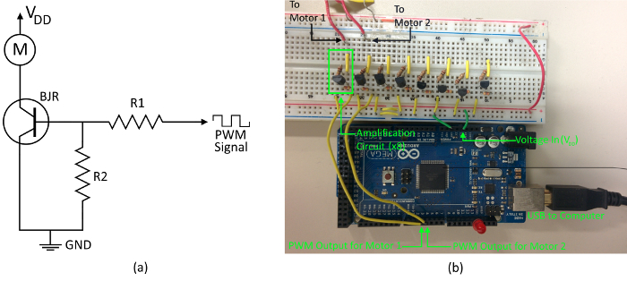
Figure 1. Motor Wiring. (A) The amplification circuit for a single vibration motor is shown. Each motor requires a separate circuit and must be connected to a unique PWM output port on the microcontroller. The VDD here represents the 3.3 V power supplied by the microcontroller board, and the resistor R2 serves as a pull-down resister to ensure the transistor switch remains open when zero voltage is applied. (B) An example of the physical wiring of two motors. Although eight individual amplification circuits are shown, only two are connected to vibration motors. In this protocol R1 = 4.7 kΩ and R2 = 100 kΩ. Please click here to view a larger version of this figure.
Access restricted. Please log in or start a trial to view this content.
Protocol
The following protocol was approved by the Research Ethics Board at Holland Bloorview Kids Rehabilitation Hospital.
1. Motor Calibration
- Connect the microcontroller board to the computer using an USB port.
- Using the original microcontroller software, upload the custom script, "Motor_and_AccelerometerTest.ino" to the board using the USB connection by clicking the "Upload" icon, denoted by the circled right arrow.
- Ensure that the vibration level is set to zero to put the motor in the off-position using the "analogWrite" command. The code should read "analogWrite(vibe1,0);".
- In the microcontroller code, specify the pulse-width modulated (PWM) output pin corresponding to the motor of interest by initializing the "vibe1" variable.
Note: PWM signals generate approximate analog outputs from the digital signals generated by the microcontroller. The pins are labeled numerically on the physical microcontroller board. For example, if the motor is connected to PWM output pin '3', then ensure that the "int vibe1 = 3;" is specified in the code.
- Connect the z-axis output of the tri-axis accelerometer to one of the analog input ports of the microcontroller board, and connect the positive and ground leads from the accelerometer to the 5V and ground (GND) ports of the microcontroller board, respectively.
- Mount the accelerometer to the vibrating motor, ensuring that its z-axis is orthogonal to the flat surface of the motor, as shown in Figure 2, and place the motor on a hard surface.
- Open the "Motor_Calibration.vi" file in the data acquisition software and connect the microcontroller to the computer through an USB port.
- Using the fields provided, specify the serial port for the microcontroller input, using the dropdown menu, as well as the sampling rate, and number of samples to collect. Note: 500 Hz sampling rate is standard for these experiments to prevent aliasing of the acceleration data, and 1,000 samples are commonly recorded.
- Using the "Motor_and_Accelerometer.ino" code, specify the desired duty cycle of the PWM pulses supplied to the vibratory motor, once again using the "analogWrite" command, and re-download the program to the microcontroller board controlling the motors (see Step 1.1). For example, to set the number of pulses to 100, the code should read "analogWrite(vibe1,100);". Table 1 lists the PWM values and their corresponding duty cycles.
- Using the Fast-Fourier Transform (FFT) display on the "MotorCalibration.vi" interface, identify the largest peak and record the corresponding vibration frequency value (from the horizontal axis).
- Repeat Steps 1.7-1.8, adjusting the PWM levels until the desired frequency is reached, recording each PWM-frequency pair. For example, if targeting a 100 Hz frequency, perform Steps 1.7-1.8 until the largest peak occurs over the 100 Hz mark on the horizontal axis.
Note: For the vibrational motors used in this protocol, the targeted vibrations should lie in the 60-400 Hz range to better match the response frequencies of the mechanoreceptors in the skin described in the literature5,10,13. - Repeat Steps 1.2.2 to 1.8 for each motor, manually recording the PWM-frequency relationship for each motor with a spreadsheet or pencil and paper.
- Open the "Experiment_1.vi" file. For each motor, right-click on the dropdown frequency menu and select "Property". Under the "Edit Items" tab, use the table to enter the desired frequencies and corresponding PWM levels determined in Steps 1.8-1.9. Select "OK" to exit.
- Repeat Step 1.11 for each virtual interface (VI) file of the system design software to be used during testing (e.g., "Experiment_2.vi", "Experiment_3.vi", etc.).
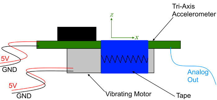
Figure 2. Accelerometer Mounted to Motor. The tri-axis accelerometer (green) is mounted to the coin motor with its z-axis orthogonal to the flat surface of the motor for calibration. Each motor was activated using different duty cycles, and the corresponding vibration frequencies were recorded by the accelerometer. Please click here to view a larger version of this figure.
2. Placing the Motors
- Once all motors have been calibrated (section 2), mount them to the thigh.
- To achieve the results described in this manuscript, place the one motor on each of the anterior, posterior, medial, and lateral surfaces of the thigh, approximately midway between the greater trochanter and lateral femoral condyle (or distal end of the limb for above-knee amputees).
Note: The specific locations of each motor can vary, depending on the research questions and regions of interest, and can be affected by anatomical and physiological factors, such as the type and spatial distribution of mechanoreceptors in the skin.
- To achieve the results described in this manuscript, place the one motor on each of the anterior, posterior, medial, and lateral surfaces of the thigh, approximately midway between the greater trochanter and lateral femoral condyle (or distal end of the limb for above-knee amputees).
- Attach motors directly to the skin using double-sided tape.
Note: Shaving the region around each motor is not necessary, but may improve their adhesion to the skin (Figure 3). For applications where the effects of clothing, a prosthetic liner, or some other material on user perception are of interest, place the motors on top of said material, rather than against the skin.
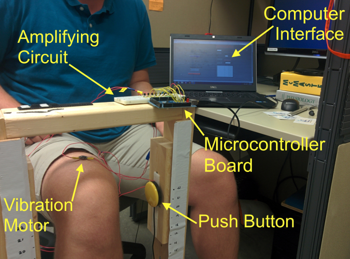
Figure 3. Test Platform for Experiments. A custom test platform was built to house the microcontroller boards and push buttons. Motors can be attached directly to the skin (as shown), or with a prosthetic liner between the motor and skin. Please click here to view a larger version of this figure.
3. Experiment 1: Applying Stimuli and Recording Reaction Time
- Re-flash the microcontroller board with the firmware to enable control of the board through the data acquisition software by opening the "LVIFA_Base.pde" file with the controller's accompanying software package, and repeating Step 1.1, replacing "Motor_and_Accelerometer_Test.ino" with the "LVIFA_Base.pde" script.
- Connect the push-button directly to one of the computer's USB ports using a serial-to-USB connector. Ensure that all required drivers are installed.
- Open the "Experiment_1.vi" interface.
- Specify the serial ports for the microcontroller board connected to the motors, and push-button by selecting the corresponding serial port identification numbers from the dropdown menus labeled "Motor Input" and "Green Button", respectively. Identify the serial port identification numbers using the computer's operating system device manager utility.
- Select the file to record the results and start the program.
- Select the motors and frequencies to be activated by selecting from the dropdown menus for each motor in the "Experiment_1.vi" interface. Have the participant press the push-button with the leg on which the feedback is applied when a vibration is felt. After the button has been pressed, confirm the response in the data acquisition software interface by noting that the clock has stopped counting, and reset the motors for the next trial by selecting the new set of frequencies from the dropdown menus.
- Once the experiment is concluded, use the dropdown menus to return all motor frequencies to the zero position and select the "Stop Program" button to terminate the connection to the motor control board.
4. Experiment 2: Distinguishing between Stimuli
Note: This experiment can be conducted entirely independently from Experiment 1. A single motor or multiple motors can be used. The specific locations of the motors can vary depending on the application and research questions.
- Connect a second push-button to another USB port using a serial-USB connector.
- Open the "Experiment_2.vi" data acquisition interface.
- Place the motors in the locations and configurations required for the specific research application. For example, place single motors on the thigh, midway between the greater trochanter and lateral femoral condyle (or the distal end of the limb for amputees), on each of the anterior, posterior, lateral, and medial surfaces of the thigh to examine the frequency sensitivity at each of these portions of the leg10,11.
- Specify the serial ports for the microcontroller board and both push-buttons using the same procedure as Step 3.4. Be sure to note which push-button is assigned to each port.
- Select the specific motors to be activated and the desired sequence of frequencies by clicking on the "Motor" icons in the software interface. For example, suppose three frequencies are being tested, such as 140 Hz, 180 Hz, and 220 Hz. A series of tests might be (1) 180 Hz followed by 140 Hz, (2) 220 Hz followed by 140 Hz, and (3) 180 Hz followed by 220 Hz.
- Input the delayed start time and stimulation duration. 1.5 sec is typical for both the delay and stimulation times.
- Start the program.
Note: The after the delay specified in Step 4.6, the program will activate the motor(s) with the sequence of paired frequencies chosen in Step 4.5. For example, if 180 Hz vs. 220 Hz was selected in Step 4.5, the corresponding motor will first vibrate at 180 Hz for the specified duration before switching to 220 Hz. - Have the participant press one of the two push-buttons to choose whether the second perceived frequency was higher or lower than the first. Responses will automatically be recorded by the program.
Access restricted. Please log in or start a trial to view this content.
Results
Figure 4 illustrates the calibration curves identifying the PWM value for a 180 Hz vibration frequency of a single motor. Starting at a 50% duty cycle, the PWM values are iterated until the primary frequency spike occurs at 180 Hz. Successful calibration trials should show a clear spike at the primary vibration frequency. Poor fixation of the accelerometer to the motor, or of the motor to a support surface may result in a more diffuse FFT without a clear spike. In this situation, the calibration trial sh...
Access restricted. Please log in or start a trial to view this content.
Discussion
The purpose of this protocol is to provide the framework for evaluating stimulation parameters in vibrotactile ASF applications. Specifically, it examines the effects of vibration frequency, amplitude, location, and sequence on user sensorimotor response. This framework can be built upon and expanded to incorporate additional or alternative types of user response that may be more clinically relevant, such as bending a joint or shifting weight from one leg to another. These types of changes would require slightly differen...
Access restricted. Please log in or start a trial to view this content.
Disclosures
The authors have nothing to disclose.
Acknowledgements
This protocol was developed for research supported by the Natural Sciences and Engineering Research Council of Canada (grant RGPIN 401963).
Access restricted. Please log in or start a trial to view this content.
Materials
| Name | Company | Catalog Number | Comments |
|---|---|---|---|
| Vibrating Pager Motors | Precision Microdrives | Model 310-101 | Coin eccentric rotating mass motors. As many as necessary to test all locations and interactions of interest |
| Tri-axis Accelerometer | Dimension Engineering | ADXL 335 | Advanced analog accelerometer. 500 Hz bandwidth, 3.5-15 V input. Designed for motion, tilt, and slope measurement, as well as vibration and shock sensing. |
| Arduino Uno | Arduino | DEV-11021 | Microcontroller board for communicating with the tri-axis accelerometer |
| Arduion Mega 2560 | Arduino | DEV-11061 | Microcontroller board for interfacing with the vibration motors. |
| LabVIEW | National Instruments | Data acquisition software used to control motors and display accelerometer signals | |
| Arduino IDE Software | Arduino | v. 1.6.5 | |
| Push-Button | Bridges | Buddy Button | Wired switch featuring a 2.5 in/6.35 cm activation surface that provides an auditory click and tactile feedback. |
| Optional: | |||
| Dedicated haptic motor driver | Texas Instruments | DRV2605L | Can be used to replace the entire amplification circuit described in Step 1. |
| Flexible wearable goniometer | Biometrics Ltd. | SG110 | Twin axis flexible goniometers to measure angles in up to two planes of movement that can be used in lieu of the push button to measure joint movement in response to stimuli. www.biometricsltd.com/gonio.htm |
References
- Tate, J. J., Milner, C. E. Real-time kinematic, temporospatial, and kinetic biofeedback during gait retraining in patients: a systematic review. Phys. Ther. 90 (8), 1123-1134 (2010).
- Onate, J. A., Guskiewicz, K. M., Sullivan, R. J. Augmented feedback reduces jump landing forces. J. Orthop. Sports Phys. Ther. 31 (9), 511-517 (2001).
- Cholewiak, R. W. The perception of tactile distance: Influences of body site, space, and time. Perception. 28 (7), 851-875 (1999).
- Zhang, Z., Wu, H., Wang, W., Wang, B. A smartphone based respiratory biofeedback system. Proc. 2010 3rd Int. Conf. Biomed. Eng. Informatics. 2, 717-720 (2010).
- Wentink, E. C., Mulder, A., Rietman, J. S., Veltink, P. H. Vibrotactile stimulation of the upper leg: Effects of location, stimulation method and habituation. Proc. Annu. Int. Conf. IEEE Eng. Med. Biol. Soc. , 1668-1671 (2011).
- Rusaw, D., Hagberg, K., Nolan, L., Ramstrand, N. Can vibratory feedback be used to improve postural stability in persons with transtibial limb loss? J. Rehabil. Res. Dev. 49 (8), 1239-1254 (2012).
- Goodworth, A. D., Wall, C., Peterka, R. J. Influence of feedback parameters on performance of a vibrotactile balance prosthesis. IEEE Trans. Neural Syst. Rehabil. Eng. 17 (4), 397-408 (2009).
- Asseman, F., Bronstein, A. M., Gresty, M. A. Using vibrotactile feedback of instability to trigger a forward compensatory stepping response. J. Neurol. 254 (11), 1555-1561 (2007).
- Fan, R. E., Culjat, M. O., et al. A haptic feedback system for lower-limb prostheses. IEEE Trans. Neural Syst. Rehabil. Eng. 16 (3), 270-277 (2008).
- Sharma, A., Torres-moreno, R., Zabjek, K., Andrysek, J. Toward an artificial sensory feedback system for prosthetic mobility rehabilitation: Examination of sensorimotor responses. J. Rehabil. Res. Dev. 51 (6), 416-425 (2014).
- Sharma, A., Leineweber, M. J., Andrysek, J. The effects of cognitive load and prosthetic liner on volitional response times to vibrotactile feedback. J. Rehabil. Res. Dev. , (2016).
- Crea, S., Cipriani, C., Donati, M., Carrozza, M. C., Vitiello, N. Providing Time-Discrete Gait Information by Wearable Feedback Apparatus for Lower-Limb Amputees: Usability and Functional Validation. IEEE Trans. Neural Syst. Rehabil. Eng. 23 (2), 250-257 (2015).
- Bolanowski, S. J., Gescheider, G. A., Verrillo, R. T., Checkosky, C. M. Four channels mediate the mechanical aspects of touch. J. Acoust. Soc. Am. 84 (5), 1680-1694 (1988).
- Giggins, O. M., Persson, U. M., Caulfield, B. Biofeedback in rehabilitation. J. Neuroeng. Rehabil. 10 (1), 60(2013).
- Shull, P. B., Jirattigalachote, W., Hunt, M. A., Cutkosky, M. R., Delp, S. L. Quantified self and human movement: A review on the clinical impact of wearable sensing and feedback for gait analysis and intervention. Gait Posture. 40 (1), 11-19 (2014).
- Goodworth, A. D., Peterka, R. J. Sensorimotor integration for multisegmental frontal plane balance control in humans. J. Neurophysiol. 107 (1), 12-28 (2012).
Access restricted. Please log in or start a trial to view this content.
Reprints and Permissions
