This protocol shows a plant sample preparation method for light-sheet microscopy. The setup is characterized by mounting the plant vertically on the surface of a gel and letting it grow in controlled bright conditions. This allows long-term observation of plant organ development in standardized conditions.
Method Article
Light Sheet Fluorescence Microscopy of Plant Roots Growing on the Surface of a Gel
In This Article
Summary
Abstract
One of the key questions in understanding plant development is how single cells behave in a larger context of the tissue. Therefore, it requires the observation of the whole organ with a high spatial- as well as temporal resolution over prolonged periods of time, which may cause photo-toxic effects. This protocol shows a plant sample preparation method for light-sheet microscopy, which is characterized by mounting the plant vertically on the surface of a gel. The plant is mounted in such a way that the roots are submerged in a liquid medium while the leaves remain in the air. In order to ensure photosynthetic activity of the plant, a custom-made lighting system illuminates the leaves. To keep the roots in darkness the water surface is covered with sheets of black plastic foil. This method allows long-term imaging of plant organ development in standardized conditions.
Introduction
One of the key questions in understanding plant development is how single cells behave during organ differentiation and growth. Ideally, cellular events, like gene expression patterns and intracellular protein localization, can be seen in the light of a larger context of the tissue. This objective poses technical challenges and requires whole organ observation with a high spatial as well as temporal resolution over prolonged periods of time, which may cause photo-toxicity effects. Since plants quickly adapt to environmental changes, the growing conditions must be tightly controlled. In order to do long-term imaging without interfering with the physiological state of the plant, three things have to be ensured, 1) growing conditions in the sample chamber, 2) stable sample mounting over long periods of time, and 3) the imaging with low light intensities to avoid photo-damage and non-physiological conditions.
Physiological growing conditions in the microscope specimen chamber are crucial for long-term experiments. There are a number of protocols available that describe imaging growth chambers for confocal microscopes1-3. However, confocal microscopy introduces high light-intensity to the plant, which can cause stress responses and usually inhibits the growth4. In addition, most conventional microscopes allow only horizontal positioning of the sample, which is not optimal for plants since they try to reorient themselves and grow towards the vector of gravity. Over the past ten years, light-sheet microscopy has emerged as a powerful tool to capture the development of large specimens at cellular resolution for time periods of up to several days5-9. Light-sheet microscopy allows positioning the specimen vertically and is increasingly used in plant research studying root development10-21, recently reviewed by Berthet and Maizel22. Many of the mentioned studies10,13-18,21 were optimized and conducted in the laboratory of Ernst H.K. Stelzer employing a special way of sample mounting characterized by growing the root on the surface of a gel17. In these studies, a custom-made microscope was used, in which the plant is held from the bottom. In contrast, the majority of broadly available light-sheet microscopes hold the sample from the top. Thus, this particular preparation method cannot be readily applied. The method presented here provides a protocol for the well-established on-surface mounting method applicable for the OpenSPIM23, an open access platform for applying and enhancing Selective Plane Illumination Microscopy (SPIM).
The overall goal of this protocol is to enable long-term imaging of Arabidopsis roots in the OpenSPIM light-sheet microscope. This is accomplished by growing a plant upright on the surface of a gel with the roots in a liquid medium while the leaves remain in the air. In order to ensure photosynthetic activity of the plant, a custom-made lighting system illuminates the leaves but not the roots (Figure 1).
Protocol
1. Arabidopsis Culturing Prior to Imaging
- Prepare ½ MS medium (half-strength Murashige and Skoog medium) by adding 2.15 g MS-medium, 10 g sucrose, 0.97 g MES (2-(N-morpholino)ethanesulfonic acid) and 1 L ddH2O (double-distilled water) into a 1 L bottle. Adjust the pH to 5.8 using KOH.
- Add 15 g/L gellan gum to the ½ MS medium and autoclave it for 20 min at 121 °C.
- Pour 30 mL of the hot medium into square Petri dishes (245 x 245 x 25 mm) to create a layer of gel with a thickness of about 2 mm. Let the dishes cool down to room temperature to allow the medium to solidify.
- Put sterilized Arabidopsis seeds into a 1.5 mL reaction tube containing 1 mL sterile H2O. Pick up the seeds using a glass pipet or a 1,000 µL pipet tip and sow them onto the surface of the gel. Place the seeds separately about 10 mm apart. Seal the plate with tape.
- Incubate the plate for 24 h at 4 °C (stratification).
- Cultivate the plate in a growth incubator, e.g. at 22 °C in a 16/8 h day/night cycle with 120-140 µmol/m²/s amount of light for 6 days. Up to 10 days old plants can be used.
2. Plant Sample Preparation Method
Note: The sample holder can be either 3D printed or hand made in a machine workshop using the dimensions depicted in Figure 2C. The 3D model file is provided in the supplemental material (Supplemental_File_-_3D_Sample_Holder.stl). See the link for ordering the 3D print in the material list.
- Add 5 g low-melt agarose into a 50 mL bottle containing 50 mL ½ MS medium and autoclave it for 20 min at 121 °C.
- Aliquot the 1% low-melt agarose solution in 1.5 mL reaction tubes. Store at 4 °C (can be used for at least two months).
- Melt an aliquot of 1%% low-melt agarose at 80 °C and let it cool down to 33 °C.
- Clean the sample holder in an ultrasound unit. Sterilize the sample holder with 70% ethanol and wash with sterile water.
- Cut the gel around the plant using a scalpel.
- Lift the block with a flat spatula and slide it carefully on the sample holder using a second spatula.
- Glue the gel on the sample holder with 1% agarose (at 33 °C) using a 100 µL pipette.
- Glue the plant on the gel with 1% agarose using a 10 µL pipette. Use a stereo microscope to verify that the leaves are not covered with gel. Do not position the gel directly on the region of interest.
- To prevent the plant from drying out, work uninterruptedly. Insert the sample holder into a 1,000 µL pipet tip whenever possible. Use the pipet tip as a cap and slide it carefully over one end of the sample holder where the plant is located.
- Put the sample holder in a pipette tip box and prepare more plants if necessary. Plants can be directly imaged or put back in the growth incubator.
3. Set up the Microscope
NOTE: The LED illumination system is a custom-built lamp. The technical details required to build the LED-ring can be found in Figure 3 and the material list. See the supplemental material file (Supplemental_File_-_LED_Ring_Board.brd) for the board design.
- Screw or glue (e.g. double sided tape) the LED ring on the lower side of the OpenSPIM x/y/z/θ-stage arm.
- Connect the LED ring with an adjustable power supply (0-30 V, max 2 A).
- Adjust the voltage to the desired light intensity (for Arabidopsis, 120-140 µmol/m2/s, Figure 3D).
- Sterilize the sample chamber with 70% ethanol and wash with sterile water.
- Clean the objective lens with benzine and lens cleaning tissue. Sterilize the objective lens with 70% ethanol.
- Connect the perfusion tubes to the sample chamber in a one-way arrangement. Put a 1 L bottle containing fresh ½ MS medium and another empty bottle next to the peristaltic perfusion pump. Connect the bottle with medium with the lower inlet of the sample chamber using one perfusion tube. Connect the upper outlet of the sample chamber with the empty bottle to trash the used medium using another perfusion tube.
- Set the speed of flow to 1 mL/min.
NOTE: To not overspill the sample chamber, it is important to have a higher outflow than the inflow. Either increase the pumping rate or use a tube with a larger inner diameter for the outflow. - Cut a black plastic foil into 3 mm small squares, wash with 70% ethanol and let them dry before placing them in the sample chamber on the water surface.
- Remove the pipet tip from the sample holder and insert the sample holder in the sample chamber. If the newly manufactured sample holder does not fit into the stage arm, use a fine sandpaper to make it thinner or use an O-ring (∅ 6 mm) in case it is too thin.
- To create the lids, cut the black aluminum foil into two 50 x 25 mm pieces. Make a 5 mm cut in the middle of one side of each piece. Fold to create a triangle indentation (Figure 1D). Close the sample chamber with the two lids by putting the lids on top of the sample chamber with the triangle indentations facing the sample holder. Make sure that the plant leaves are not in shade of the lids and receive light from the illumination system.
- Find the region of interest using the x/y/z and rotation stage to position an emerging lateral root in the field of view.
- Before recording, allow the system to equilibrate for at least 15 min.
- Setup the image acquisition.
- Set a stack of 217 images with 3 µm z-spacing (650 µm) and set the time lapse with 15 min imaging interval for a total period of 17 h.
NOTE: A detailed documentation on how to operate the OpenSPIM software can be found on (http://openspim.org/Acquisition#Acquiring_a_Stack).
- Set a stack of 217 images with 3 µm z-spacing (650 µm) and set the time lapse with 15 min imaging interval for a total period of 17 h.
- Start recording.
Results
This sample preparation method allows the cultivation of the plant inside the microscope sample chamber while observing the root system with a light-sheet microscope (Figure 1). The plant grows on the surface of a layer of gel (½ MS medium containing 1.5% gellan gum) mounted on a custom designed sample holder (Figure 2). The sample holder is 3D printed using a transparent resin as material. A manufactured version highlighting the dimensions is depicted in Figure 2C. The roots are immersed in liquid (½ MS medium), which is continuously refreshed by a perfusion system. The leaves remain in the air and are continuously illuminated with a light intensity of 130 µmol/m²/s coming from blue and red LEDs that are arranged in a ring above the plant (Figure 1A, B and Figure 3A-C). The LED ring is manufactured in our machine workshop and we provide technical details on how to build the LED-ring in the Figure 3 and the material list. The light intensity can be continuously adjusted ranging from 30-250 µmol/m2/s (Figure 3D). The root system is shaded by small sheets of a black plastic foil covering the water surface (Figure 1). Any stray light from the illumination that is collected by the detection lens is filtered by the GFP filter (Figure 3E).
With this setup, a time lapse of a growing Arabidopsis lateral root was recorded for 17 h using a 20X/0.5 lens (Figure 4). The lateral root has its origin in the pericycle cell layer, which is located deep inside the primary root. In order to demonstrate the imaging capabilities even deeper inside of a tissue for prolonged time periods, a higher magnification (40X/0.75) was used to capture the formation of a lateral root from the first stage primordium until the emergence out of the primary root within a time period of 38 h (Figure 5). An exemplary 2D slice of the data set is shown in Fig. 5B. This recording allows us to follow the dynamics of lateral root formation in 3D (Figure 5A) with a cellular resolution.
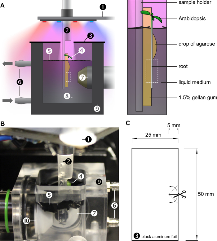
Figure 1: Growing conditions inside the OpenSPIM sample chamber. A) Sketch of the imaging chamber. The plant is growing upright on the surface of a gel, mounted on a custom built sample holder (see also Figure 2). The roots are growing in a liquid medium, which is continuously exchanged by a perfusion system. The plant leaves grow in air and are illuminated by red and blue LEDs (see also Figure 3). The root system is shaded with small sheets of a black plastic foil covering the water surface. A lid made of two pieces of black aluminum foil further reduces the amount of light below the water surface and maintains humidity in the sample chamber. The magnified panel on the right highlights the plant growing on the surface of a block of gel immersed in the liquid medium. A drop of agarose mounts the root onto the gel. The dashed box indicates the region of interest observed by the microscope. B) Photograph of the imaging chamber (without lid). Numbers (1)-(10) in A and B represent: (1): x/y/z/θ-stage with LED ring, (2): sample holder, (3): lid, (4): Arabidopsis thaliana, (5): sheets of black plastic foil, (6): perfusion system, (7): detection objective lens, (8): liquid medium, (9): sample chamber, (10): illumination objective lens. C) The lid is made of two pieces of black aluminum foil. Please click here to view a larger version of this figure.
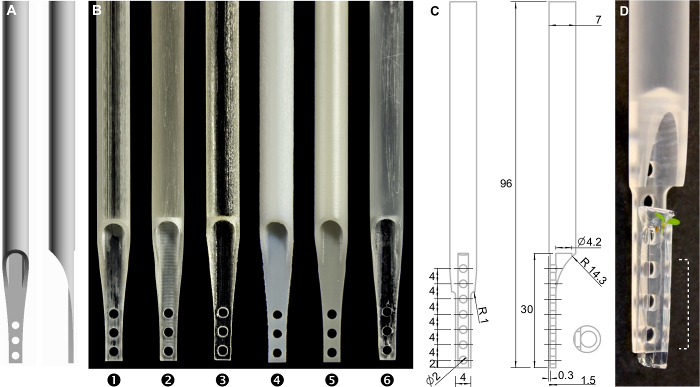
Figure 2: The sample holder. A) 3D model. The 3D model file is provided in the supplemental material. B) Photograph of 3D prints using different materials (1)-(3): transparent acrylic plastics, (4) and (5): resin, (6): transparent resin. C) Technical drawing of the sample holder, numbers represent millimeter. D) Photograph of the manufactured sample holder with a plant mounted. The dashed area can be observed by the microscope. Please click here to view a larger version of this figure.
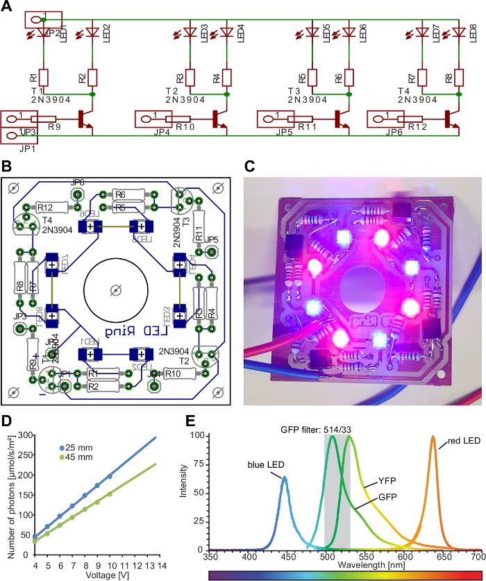
Figure 3: Plant illumination setup. A) Schematic circuit diagram of the lamp. Pairs of LEDs can be switched on/off individually for directional lightning. LED: light-emitting diode, R: resistance, T: transistor, JP: pinhead. B) The final design of the illumination lamp was drawn using a PCB-software (PCB: printed circuit board). We provide the board design file in the supplemental material. The board was then manufactured and assembled in our institute's MIBA machine shop. C) Photograph of the LED ring switched on. Four pairs of a red and a blue LED are arranged in a ring. D) The range of voltage can be adjusted between 3.5 V and 14.0 V. Resistances were used to reach the amount of light ranging from 30-250 µmol/m2/s (R1-8: 220 Ohm, R9-12: 1,220 Ohm). E) The emission spectrum of the lamp, GFP and YFP. Please click here to view a larger version of this figure.
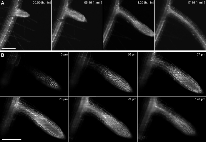
Figure 4: Time lapse recording of Arabidopsis thaliana lateral root. The 5 days old seedling expresses a membrane marker (pUBQ10::YFP-PIP1;4) and a nuclear reporter (pGATA23::nls-GUS-GFP) specifically marking pericycle cells that develop into a lateral root. A stack of 217 images (3 µm z-spacing) was captured every 15 min for 17 h recording using a 20X/0.5 lens. A) Four time points out of 69 are shown in a maximum intensity projection. B) Six out of 217 single slices of a z-stack of one time point are shown. Scale bars in A and B represent 100 µm. Please click here to view a larger version of this figure.
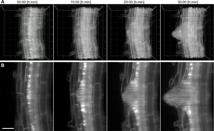
Figure 5: Time lapse recording of Arabidopsis thaliana lateral root. The 6 days old seedling expresses a membrane marker (pUBQ10::YFP-PIP1;4) and a nuclear reporter (pGATA23::nls-GUS-GFP) specifically marking pericycle cells that develop into a lateral root. A stack of 200 images (1.5 µm z-spacing) was captured every 15 min for 38 h recording using a 40X/0.75 lens. A) 3D rendering of four time points, the numbers in the grid represent µm, B) single slice through the central plane of the main root. Scale bar represents 50 µm. Please click here to view a larger version of this figure.
Supplemental_File_-_3D_Sample_Holder.stl. The 3D model file is provided. Please click here to download this file.
Supplemental File LED Ring Board.brd. The board design file is provided. Please click here to download this file.
Discussion
Light Sheet Fluorescence Microscopy has the great advantage to combine low phototoxicity and ultrafast acquisition speed, which can be used to capture a large volume with a high spatio-temporal resolution while keeping the sample in a physiological state. The resolution of a light sheet microscope can be compared to that of a confocal microscope9. However, light scattering and absorption occurs along the excitation and emission path individually and the overall image quality can be significantly lower inside opaque tissues compared to the surface. To circumvent this complication one can use the possibility to rotate the sample along the vertical axis and observe the same volume from different directions. But this is not always advantageous, e.g. lateral roots emerge on one side of the root and imaging from behind results in a low image quality without gaining more information. However, the rotation can be principally used to position the sample in the best way. The classic horizontal arrangement of the objective lenses allows for new ways of sample mounting. Plants benefit from a vertical position. Presented here, the "on the surface of the gel" mounting method has several advantages compared to other mounting methods such as embedding the root inside of a gel24,25. 1) The root system is in direct contact with the liquid medium. The sample chamber is connected to a perfusion system which provides continuously fresh medium. It can also be used to rapidly exchange the entire volume of the sample chamber to apply different media or drugs. 2) Prior to sample preparation plants grow as they are used to grow in laboratories. Plants can be selected under a fluorescence microscope and only the desired plants need to be prepared. 3) The plant is transferred from the Petri dish to the sample holder without being touched. Thereby the plant can further develop on the same gel it was growing on in the growth incubator and mechanical stress is reduced to a minimum. 4) The view on the specimen is unobstructed and optical aberrations are minimized because the space between the sample and the detection objective is solely filled with medium and no other materials with differing refractive indices.
In order to perform long-term imaging, the plant illumination system is necessary to ensure photosynthetic activity of the plant. In most laboratories plants grow on a transparent gel, i.e. the roots are exposed to light. This may cause different responses to their environment and induces changes in their biochemistry and development26,27. In order to reduce the amount of light on the root system, black plastic foil was used to cover the water surface as well as a lid made of black aluminum foil covered the sample chamber. Light can reach the plant leaves through the central hole in the lid. In this setup, no increase in background light was observed, suggesting that the amount of stray light from the red and blue LEDs was significantly reduced by the GFP filter and the shading approaches. This allowed keeping the light turned on during image acquisition without increasing the camera background noise.
The sample holder is designed for 3D printing. However, the choice of material is crucial as several plastics that were tested were not 100% stable, resulting in a drift of the sample. Therefore, it is recommended to use resins instead or build the sample holder by milling a Polyethylene (PEP) rod. When using a light sheet microscope setup with double-sided illumination system the sample holder might interfere with one of the light sheets depending on the rotation angle. To reduce mechanical stress during scooping the plant from the plate, use a flat angle of the spatula. The plant can quickly dry out and experience air flow for the very first time. Try to avoid any air draft (rapid movements, air-condition flow), work uninterruptedly and slide the sample holder into a 1,000 µL pipet tip whenever possible. Inside the microscope, it is crucial to not dip the whole plant in liquid and keep the leaves dry.
The technique is ideal for imaging early stages of lateral root formation. When performing long term imaging of mature root tips one must keep in mind that Arabidopsis roots grow with 100-300 µm/h rapidly out of the field of view. A very useful future implementation could be an automated tracking algorithm, which would allow following root tip growth over prolonged periods of time. The ability to control environmental conditions such as light and nutrient composition of the medium during the acquisition process allows investigating how plants adapt to changes. The root is in direct contact with the liquid medium, which can be used to apply drugs to chemically activate gene expression, for example using the dexamethasone inducible28 or the β-estradiol inducible system29. However, it takes time to exchange the entire volume of the sample chamber to wash out a drug. The setup could be improved by minimizing the volume of the sample chamber to accelerate medium exchange. Nevertheless, this technique has a great potential. The combination of mounting procedure, standardized growing conditions and the gentle image acquisition using light-sheet microscopy allows long-term studies of plant development with high resolution at a physiological level. This will help researchers to explore fundamental mechanisms of plant development.
Disclosures
The authors have nothing to disclose.
Acknowledgements
We thank Matyáš Fendrych for critical reading/viewing and Stephan Stadlbauer for the audio equipment. Thanks to the Miba Machine Shop at IST Austria for their contribution to the OpenSPIM. The research leading to these results has received funding from the People Programme (Marie Curie Actions) of the European Union's Seventh Framework Programme (FP7/2007-2013) under REA grant agreement n° [291734] and European Research Council (project ERC-2011-StG-20101109-PSDP).
Materials
| Name | Company | Catalog Number | Comments |
|---|---|---|---|
| Agarose, low melting | VWR | AFFY3282125GM | |
| Black aluminum foil | Thorlabs | BKF12 | |
| Black plastic foil | Carl Roth | HT83.2 | |
| LED blue (453 nm) | OSRAM | LD CN5M-1R1S-35-1 | |
| LED red (625 nm) | OSRAM | LR T66F-ABBB-1-1 | |
| LED board - PCB design software | Cadsoft Eagle | ||
| MES monohydrate | Duchefa | M1503.0100 | |
| Micropore Surgical Tape | 3M | 1530-1 | |
| Murashige & Skoog Medium (MS-Medium) | Duchefa | M0221 | |
| Phytagel | Sigma-Aldrich | P8169 | |
| Sample holder 3D print | i.materialise | https://i.materialise.de/shop/item/sampleholder-openspim-zeisslightsheetz1 | |
| Square Petri dishes (245 x 245 x 25 mm) | VWR | 734-2179 | |
| Sucrose | Sigma-Aldrich | 84097-1KG |
References
- Grossmann, G., Guo, W. -J., et al. The RootChip: an integrated microfluidic chip for plant science. Plant Cell. 23 (12), 4234-4240 (2011).
- Busch, W., Moore, B. T., et al. A microfluidic device and computational platform for high-throughput live imaging of gene expression. Nat Methods. 9 (11), 1101-1106 (2012).
- Calder, G., Hindle, C., Chan, J., Shaw, P. An optical imaging chamber for viewing living plant cells and tissues at high resolution for extended periods. Plant Methods. 11 (1), 22(2015).
- Dixit, R., Cyr, R. Cell damage and reactive oxygen species production induced by fluorescence microscopy: effect on mitosis and guidelines for non-invasive fluorescence microscopy. Plant J. 36 (2), 280-290 (2003).
- Huisken, J., Swoger, J., Del Bene, F., Wittbrodt, J., Stelzer, E. H. K. Optical Sectioning Deep Inside Live Embryos by Selective Plane Illumination Microscopy. Science. 305 (5686), 1007-1009 (2004).
- Keller, P. J., Schmidt, A. D., Wittbrodt, J., Stelzer, E. H. K. Reconstruction of Zebrafish Early Embryonic Development by Scanned Light Sheet Microscopy. Science. 322 (5904), 1065-1069 (2008).
- Keller, P. J., Schmidt, A. D., et al. high-contrast imaging of animal development with scanned light sheet-based structured-illumination microscopy. Nat Methods. 7 (8), 637-642 (2010).
- Höckendorf, B., Thumberger, T., Wittbrodt, J. Quantitative Analysis of Embryogenesis: A Perspective for Light Sheet Microscopy. Dev Cell. 23 (6), 1111-1120 (2012).
- Stelzer, E. H. K. Light-sheet fluorescence microscopy for quantitative biology. Nat Methods. 12 (1), 23-26 (2015).
- Maizel, A., Von Wangenheim, D., Federici, F., Haseloff, J., Stelzer, E. H. K. High-resolution live imaging of plant growth in near physiological bright conditions using light sheet fluorescence microscopy. Plant J. 68 (2), 377-385 (2011).
- Sena, G., Frentz, Z., Birnbaum, K. D., Leibler, S. Quantitation of Cellular Dynamics in Growing Arabidopsis Roots with Light Sheet Microscopy. PLoS ONE. 6 (6), e21303(2011).
- Costa, A., Candeo, A., Fieramonti, L., Valentini, G., Bassi, A. Calcium Dynamics in Root Cells of Arabidopsis thaliana Visualized with Selective Plane Illumination Microscopy. PLoS ONE. 8 (10), (2013).
- Šamajová, O., Takáč, T., von Wangenheim, D., Stelzer, E. H. K. Update on methods and techniques to study endocytosis in plants. Endocytosis in Plants. , 1-36 (2012).
- Rosquete, M. R., Von Wangenheim, D., et al. An auxin transport mechanism restricts positive orthogravitropism in lateral roots. Curr Biol. 23 (9), 817-822 (2013).
- Lucas, M., Kenobi, K., et al. Lateral root morphogenesis is dependent on the mechanical properties of the overlaying tissues. Proc Natl Acad Sci USA. 110 (13), 5229-5234 (2013).
- Vermeer, J., von Wangenheim, D., et al. A Spatial Accommodation by Neighboring Cells Is Required for Organ Initiation in Arabidopsis. Science. 343 (6167), 178-183 (2014).
- Von Wangenheim, D., Daum, G., Lohmann, J. U., Stelzer, E. H. K., Maizel, A. Live Imaging of Arabidopsis Development. Arabidopsis Protocols. 1062, 539-550 (2014).
- Berson, T., von Wangenheim, D., et al. Trans-Golgi network localized small GTPase RabA1d is involved in cell plate formation and oscillatory root hair growth. BMC Plant Biol. 14 (1), 252(2014).
- Langhans, M., Meckel, T. Single-molecule detection and tracking in plants. Protoplasma. 251 (2), 277-291 (2014).
- Novak, D., Kucharova, A., Ovecka, M., Komis, G., Samaj, J. Developmental nuclear localization and quantification of GFP-tagged EB1c in Arabidopsis root using light-sheet microscopy. Front Plant Sci. 6, (2015).
- Von Wangenheim, D., Fangerau, J., et al. Rules and Self-Organizing Properties of Post-embryonic Plant Organ Cell Division Patterns. Curr Biol. 26 (4), 439-449 (2016).
- Berthet, B., Maizel, A. Light sheet microscopy and live imaging of plants. J Microsc. , (2016).
- Pitrone, P. G., Schindelin, J., et al. OpenSPIM: an open-access light-sheet microscopy platform. Nat Methods. 10 (7), 598-599 (2013).
- de Luis Balaguer, M. A., et al. Multi-sample Arabidopsis Growth and Imaging Chamber (MAGIC) for long term imaging in the ZEISS Lightsheet Z.1. Dev Biol. 419 (1), (2016).
- Ovečka, M., Vaškebová, L., Komis, G., Luptovčiak, I., Smertenko, A., Šamaj, J. Preparation of plants for developmental and cellular imaging by light-sheet microscopy. Nat Protoc. 10 (8), 1234-1247 (2015).
- Yokawa, K., Kagenishi, T., Kawano, T., Mancuso, S., Baluška, F. Illumination of Arabidopsis roots induces immediate burst of ROS production. Plant Signal Behav. 6 (10), 1460-1464 (2011).
- Silva-Navas, J., et al. D-Root: a system for cultivating plants with the roots in darkness or under different light conditions. Plant J. 84 (1), 244-255 (2015).
- Aoyama, T., Chua, N. -H. A glucocorticoid-mediated transcriptional induction system in transgenic plants. Plant J. 11 (3), 605-612 (1997).
- Brand, L., et al. A versatile and reliable two-component system for tissue-specific gene induction in Arabidopsis. Plant Physiol. 141 (4), 1194-1204 (2006).
Reprints and Permissions
