The H1 deep transcranial magnetic stimulation coil is FDA-cleared for the treatment of depression. We demonstrate how to utilize the H1 for other conditions, such as auditory hallucinations and PTSD, by moving the helmet to different locations over the subject's skull.
Method Article
How to Use the H1 Deep Transcranial Magnetic Stimulation Coil for Conditions Other than Depression
Opens in a new tab
In This Article
Summary
Loading...
$$\rightleftharpoonup{xx}$$
$$\longleftharp{xx}$$,
$$\longrightharp{xx}$$,
Abstract
Loading...
$$\rightleftharpoonup{xx}$$
$$\longleftharp{xx}$$,
$$\longrightharp{xx}$$,
Deep transcranial magnetic stimulation (dTMS) is a relatively new technique that uses different coils for the treatment of different neuropathologies. The coils are made of soft copper windings in multiple planes that lie adjacent to the skull. They are located within a special helmet so that their magnetic fields combine and improve depth penetration. The H1 dTMS coil is designed to stimulate bilateral prefrontal cortices with greater effective stimulation over the left than the right. By positioning the left side of the coil close to the left dorsolateral prefrontal cortex (DLPFC), the H1 coil was used in a multisite study, leading to FDA approval for treatment-resistant depression. In this same position, the H1 coil was also explored as a possible treatment for negative symptoms of schizophrenia, bipolar depression, and migraine. When moved to different positions over the subject's skull, the H1 coil was also explored as a possible treatment for other conditions. Such manipulation of the H1 coil was demonstrated for PTSD and alcohol dependence by positioning it over the medial prefrontal cortex (mPFC), for anxiety by positioning it over the right prefrontal cortex (rPFC), for auditory hallucinations and tinnitus by positioning it over the temporoparietal junction (TPJ), and for Parkinson's and fatigue from multiple sclerosis (MS) by positioning it over the motor cortex (MC) and PFC. Corresponding electrical field diagrams measured with an oscilloscope through a saline-filled head are included.
Introduction
Loading...
$$\rightleftharpoonup{xx}$$
$$\longleftharp{xx}$$,
$$\longrightharp{xx}$$,
Until recently, only superficial, repetitive transcranial magnetic stimulation (rTMS) coils, such as the circular, figure-8, or double-cone coils, were available. Although those coils could easily be moved anywhere over the skull to target altered brain activity in different disorders, the decay of their electrical fields was quite rapid. This fast decay limited their efficacy and made them impractical for use in cases where deeper stimulation is necessary, since the high stimulator output that is required can be dangerous and painful to the patient. Moreover, the focality of figure-8 and double-cone coils truly requires neuro-navigation, especially if one wants to be certain that they are affecting the correct anatomical target1,2,3.
In recent years, the clinical use of rTMS has progressed because of two factors. The first is advances in functional neuroimaging, clarifying meaningful and specific neuroanatomical targets for psychiatric and neurological symptoms and disorders. The second is advances in bioengineering that enabled the delivery of non-invasive, tolerable, high-frequency stimulation to deep brain regions with specifically-designed dTMS H-coils4,5 and improved cooling technologies (long cooling time between trains results in very long treatment sessions). Together, these developments allow long-term normalization of pathological brain activity in a variety of targets that were identified for a specific symptom or condition. The combination of these advances greatly expands the physician's toolbox, changing the practice of psychiatry and neurology, as it provides a safe and effective way to treat even drug-resistant patients.
There are fourteen different H-coils designed to target specific brain regions, and they are available for research or for clinical use in different countries. However, only the H1 coil is FDA-cleared for commercial use, and therefore, among the different H-coils, it is the most accessible coil for patients. Because of this, it is important for clinicians to be familiar with the alternative protocols that can be administered using the H1 coil and how each can be used to benefit their refractory patients. It is important to qualify that there are better-designed H-coils for symptoms that cannot be alleviated by targeting the left DLPFC. However, since the H1 coil is currently the most readily-available H-coil, this paper is intended to explain how to position it appropriately in an off-label fashion.
Protocol
Loading...
$$\rightleftharpoonup{xx}$$
$$\longleftharp{xx}$$,
$$\longrightharp{xx}$$,
NOTE: Before beginning any TMS protocols, there are three precautionary statements. First, patients and operators should use earplugs with a 30 dB rating. Second, patients with ferromagnetic material in the skull cannot receive TMS. Finally, patients with epilepsy must have protocol modifications. In addition, the individual's motor threshold (MT) must be determined (see below for the specific procedure). The MT is defined as the lowest machine intensity necessary to activate a muscle in five out of ten attempts (50%), typically the abductor pollicis brevis, by visual inspection. MT is used to adjust the stimulator output for the specific individual receiving the treatment. Each protocol includes specific parameters, such as the stimulation frequency, the number of trains, the inter-train interval (ITI), or the number of pulses in each train. Each disorder has a minimum number of daily or thrice-weekly treatments that should be attempted before someone can be considered a treatment failure, and responders generally need a prolonged course of twice-weekly treatments to get maximal sustained benefit. Additionally, patients in recovery may benefit from weekly maintenance treatments. Continuation and maintenance protocols for the different disorders are still being studied, but all of the parameters that were used in the preliminary investigations are provided in Table 1 and should be referred to for each specific disorder. Patients undergoing dTMS should have a baseline assessment with clinician and patient rating scales, as well as follow-up scales. The definition of disease states and the rating scale options to define improvement and remission are beyond the scope of this paper. An example of a patient rating scale for depression would be the quick inventory of depressive symptoms or the Beck depression inventory. An example of a clinician rating scale is the clinician's global impression or the Hamilton depression rating scale. These scales have defined cutoffs for remission, while a 50% drop in the score is defined as response.
| Disorder | Anatomical Target/ H1 Position | Stimulation Protocols | Treatment Frequency | Treatment Changes |
| MDD6,7,8 | Left PFC Coil tilted | 120 MT, 18 HZ, 2 sec train, 20 sec interval, 55 trains, 1,980 total pulses | 5d a week until remission or sustained improvement. If unimproved after 44 treatments choose an alternative treatment approach. | After sustained improvement for two weeks or remission decrease frequency to 2x week for three months. |
| Bipolar Depression9,10 | Left PFC Coil tilted | 120 MT, 20 HZ, 2 sec train, 20 sec interval, 42 trains, 1,680 total pulses | 5d a week until remission or sustained improvement. If unimproved after 20 treatments choose an alternative treatment. | If the patient is in remission or sustained improvement, continue treatments twice a week for a period of three months. |
| Schizophrenia - Negative Symptoms11,12 | Left PFC Coil tilted | 120 MT, 20 HZ, 2 sec train, 20 sec interval, 42 trains, 1,680 total pulses | 5d a week until remission or sustained improvement If the patient is unimproved after 20 treatments choose an alternative treatment. | If the patient is in remission or sustained improvement, continue treatments twice a week for a period of three months. |
| Migraine13 | Left PFC Coil tilted | 100 MT, 10 HZ, 2 sec train, 20 sec interval, 18 trains, 360 total pulses | 3d a week for four weeks. If the patient does not respond after 12 sessions, choose an alternative treatment. | If the patient is in remission or sustained improvement, continue treatments twice a week for a period of three months. |
| PTSD14 | Medial PFC Coil symmetrical | After listening to a personalized traumatic script, 120 MT, 20 HZ, 2 sec train, 20 sec interval, 42 trains, 1680 total pulses | 3d a week for 5 weeks. If the patient does not respond after 15 treatments, choose an alternative treatment. | If the patient goes into remission or has a sustained improvement, continue treatments twice a week for a period of three months. For complex PTSD with multiple traumatic events, change the traumatic script and start again |
| Alcohol Addiction15,16,17,18,19 | Medial PFC Coil symmetrical | After 90 sec personalized provocation of alcohol cravings, 120 MT, 20 HZ, 2.5 sec train, 30 sec interval, 30 trains, 1,500 total pulses | 5d a week until remission or sustained improvement. If the patient is does not respond after 20 treatments choose an alternative treatment. | If the patient goes into remission, continue treatments twice a week for a period of three months. |
| Schizophrenia - Auditory hallucinations20,21 | Left TPJ Coil tilted | 110 MT, 1 HZ, 600 Pulses | 5d a week for 4 weeks. If the patient does not respond after 20 sessions, choose an alternative treatment. | If the patient goes into remission or has a sustained improvement, continue treatments twice a week for a period of three months. |
| Chronic Tinnitus22 | Left TPJ Coil tilted | 110 MT, 18 HZ, 2 sec train, 20 sec interval, 55 trains, 1,980 total pulses | 5d a week for 2 weeks. If the patient does not respond after 10 sessions, choose an alternative treatment. | If the patient goes into remission or has a sustained improvement, continue treatments twice a week for a period of three months. |
| Anxiety23 | Right PFC Coil tilted | 120 MT 1 HZ 600-2,000 Pulses | 5d a week for 6 weeks. If the patient does not respond after 30 sessions, choose an alternative treatment. | If the patient goes into remission or has a sustained improvement, continue treatments twice a week for a period of three months. |
| Parkinson’s Disease24 | Motor Cortex and PFC Coil symmetrical | Motor Cortex: 110 MT, 1 HZ, 1,000 Pulses PFC: 120 MT, 20 HZ, 2 sec train, 20 sec interval 50 trains, 2,000 pulses | 5d a week for 4 weeks. If the patient does not respond after 20 sessions, choose an alternative treatment. Responders may lower levodopa dosage. | After sustained response continue treatments twice a week to achieve maximum benefit. Patients will regress after three months without maintenance. |
| MS Fatigue25 | Motor Cortex and PFC Coil symmetrical | Motor Cortex: 80 MT, 10 HZ, 2 sec train, 1 sec interval, 70 trains, 1,400 total pulses PFC: 120 MT, 18 HZ, 2 sec train, 20 sec interval, 39 trains, 1,404 total pulses | 5d a week for 4 weeks. If the patient does not respond after 20 sessions, choose an alternative treatment. | Patients should receive booster treatments on an as needed basis. |
NOTE: H1 Protocol: The focus of this paper is to demonstrate the positioning of the coil over the MC, lPFC, mPFC, rPFC, and left TPJ (see steps 2-7 below). It will not focus on programing the stimulator. That information is more readily available in the instructions for use that comes with the device. These protocols were designed in accordance with the principles outlined in the declaration of Helsinki.
1. Measure the Motor Threshold
- Place the blue cap with the two intercepting rulers on the subject.
- Place the 0-cm mark of the white sagittal ruler on the nasion and the 25 cm mark of the clear coronal ruler at 40% of the nasion-inion distance, with the 0 on the left side of the patient's head.
- Use the helmet to find the resting MT of the right hand, starting with the front of the helmet 7 cm from the nasion and the left side of the coil tilted 2 cm to the right.
- Using the "Single Pulse" mode on the stimulator touch screen, administer single pulses at 50% of the stimulator output while observing the patient's resting right hand. Increase the stimulator intensity if no visible movement is observed or if a visible movement is observed less than 50% of the time. Initially, use 5% intervals.
- Decrease the stimulator intensity if a visible movement is observed more than 50% of the time. Start with 5% intervals and then fine-tune it.
- Repeat steps 1.4 and 1.5 to identify the minimal MT. This location is called the "hot spot."
2. Setting Up Parameters Within the Device User Interface
- Press "Repetitive Mode" on the stimulator touchscreen.
- Enter parameters by touching the boxes on the screen and adjusting them using the side wheel. Enter the parameters from Table 1 and press "Run Session."
- Arm the machine by pressing the green button. Warn the patient that the stimulation is starting, and start the stimulation with the yellow button or the pedal.
3. Stimulate the MC for Parkinson's or MS Fatigue
- After finding the MT, straighten the helmet in a symmetrical fashion over the MC, with the 0 on the front of the helmet over the sagittal ruler.
4. Stimulate the Left PFC for Depression, Bipolar Depression, Negative Symptoms of Schizophrenia, and Migraine
- Advance the tilted helmet from the MT location over the MC to the left PFC by moving it 6 cm forward along the sagittal ruler.
5. Stimulate the mPFC for Alcohol Dependence or PTSD
- Place the helmet over the mPFC, symmetrically with respect to right-left, with the 0 mark on the helmet's front edge aligned with the 3 cm mark on the sagittal ruler of the cap (i.e., 3 cm from the nasion).
6. Stimulate the Right PFC for Generalized Anxiety or Panic Disorder
- Find the left-hand MT with the helmet (following the mirror image of steps 1.3-1.4 by tilting the helmet 2 cm to the left and watching the resting left hand).
- Move the tilted helmet 6 cm forward along the sagittal ruler to the right PFC.
7. Stimulate the Left TPJ for Tinnitus or Auditory Hallucinations
- Place the helmet over the left TPJ by moving the coil 4.5 cm posteriorly and 6.5 cm laterally (to the left shoulder) from the right-hand MC "hot spot."
8. Electrical Field Measurements
- Attach the coil to an inverted saline-filled head over the left DLPFC. Set the stimulator intensity to 50%. Using a dipole probe connected to an oscilloscope, move it cm by cm so that, when single pulses are delivered through the coil, the oscilloscope measures the induced electric field at each point in the saline-filled head26.
NOTE: The process of producing field maps based on the head model measurements is beyond the scope of this paper. In short, the field values at any point are normalized according to the relevant protocol. For instance, for depression, the accepted protocol is 120% of MT. Hence, the field values are scaled so that the value at the hand MC is 120 V/m, while the threshold for neural stimulation is defined as 100 V/m. Then, a color map of the electric field distribution in the brain is produced, where pixels with a field of 100 V/m or above are indicated in red so that one can see which brain regions are stimulated above the threshold for neural stimulation. The colored field maps are superimposed on MRI scans of the brain26,27.
Results
Loading...
$$\rightleftharpoonup{xx}$$
$$\longleftharp{xx}$$,
$$\longrightharp{xx}$$,
See the references in Table 1 for preliminary results of the various protocols. Figures 2-5 are representative electric field diagrams of the H1 coil in different anatomical positions. One example of H1 manipulation to a different position was with PTSD patients that failed to benefit from antidepressants or psychotherapy14. In this study, the H1 coil was positioned over the mPFC. As seen in Figure 3, positioning the coil in this fashion clearly stimulates the mPFC; this is not the same pattern of neuronal activation that is seen when the H1 coil is placed over the left PFC, in Figure 2. Thirty PTSD patients were randomly assigned to receive dTMS after brief exposure to a recorded script of their traumatic event, dTMS after brief exposure to a non-traumatic script, or sham stimulation after brief exposure to their traumatic script. The stimulation administration consisted of 12 sessions (3 per week for 4 weeks) of 20-Hz stimulation at 120% of MT, with forty-two 2 sec trains and a 20 sec inter-train interval for a total of 1,680 pulses. The primary outcome measure was the CAPS score at four weeks. A graphical representation of the selected results can be seen in Figure 614. Analysis of the results revealed a significant improvement only in the group that received active dTMS after brief exposure to the traumatic event, with a group x time interaction for the intrusion component of the CAPS. Following completion of this study, a multi-center study of dTMS to the mPFC for PTSD was initiated.
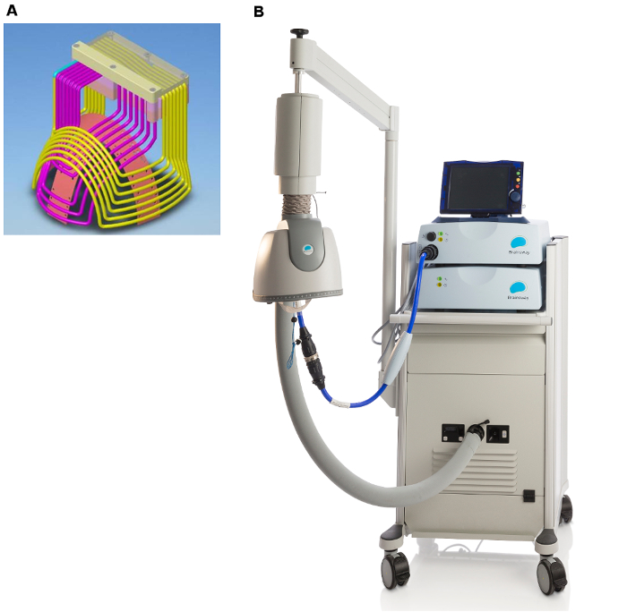
Figure 1: Deep TMS Device. Wire diagram of the H1 coil (a) and photograph of the dTMS system with the H1 helmet, positioning arm, stimulator, cooling system, and cart (b). Please click here to view a larger version of this figure.
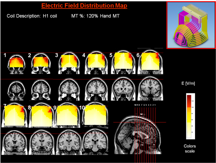
Figure 2: Electric Field Diagram of the H1 Over the Left PFC. Colored field maps indicate the absolute magnitude of the electrical field in each pixel at 120% MT of the hand for 10 coronal slices 1 cm apart. Red pixels indicate regions with a field intensity above the threshold for neuronal activation, which is 100 V/m. Please click here to view a larger version of this figure.
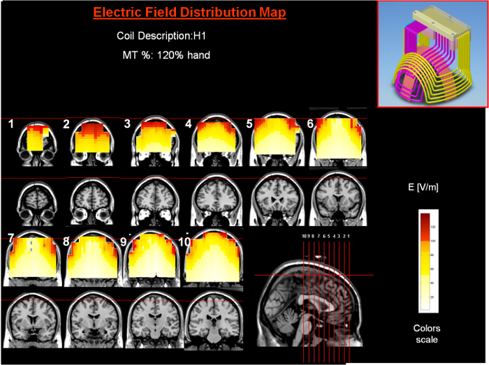
Figure 3: Electric Field Diagram of the H1 Over the Medial PFC. Colored field maps indicate the absolute magnitude of the electrical field in each pixel at 120% of the hand MT for 10 coronal slices 1 cm apart. Red pixels indicate regions with a field intensity above the threshold for neuronal activation, which is 100 V/m. Please click here to view a larger version of this figure.
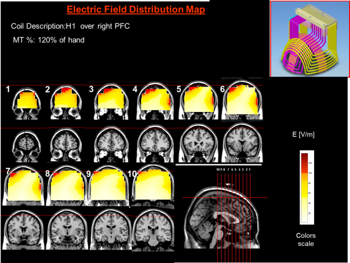
Figure 4: Electric Field Diagram of the H1 Over the Right PFC. Colored field maps indicate the absolute magnitude of the electrical field in each pixel at 120% MT of the hand for 10 coronal slices 1 cm apart. Red pixels indicate regions with a field intensity above the threshold for neuronal activation, which is 100 V/m. Please click here to view a larger version of this figure.
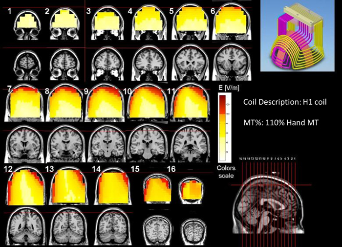
Figure 5: Electric Field Diagram of the H1 Over the Left TPJ. Colored field maps indicate the absolute magnitude of the electrical field in each pixel at 110% MT of the hand for coronal slices 1 cm apart. Red pixels indicate regions with a field intensity above the threshold for neuronal activation, which is 100 V/m. This figure is modified from Reference 28. Please click here to view a larger version of this figure.
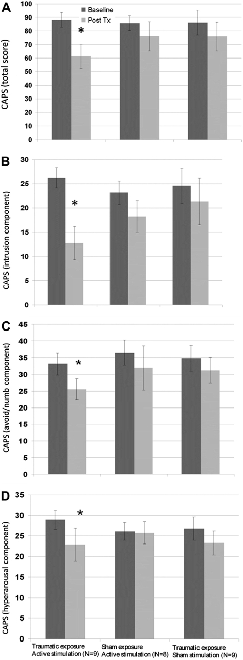
Figure 6: Clinician-administerd PTSD Scale (CAPS) Severity Score at Baseline and Post-treatment in the First (blinded) Phase. Panel A depicts the total CAPS score, while Panels B, C, and D show the intrusion, avoidance/numbing, and hyper-arousal components, respectively. Values are presented as the mean ± the standard errors. *P <0.05 relative to baseline. Reused with permission from reference14. Please click here to view a larger version of this figure.
Discussion
Loading...
$$\rightleftharpoonup{xx}$$
$$\longleftharp{xx}$$,
$$\longrightharp{xx}$$,
Critical Steps Within the Protocol
The most important component of any dTMS protocol is the correct measurement of the MT. The MT determines the individualized dosage or stimulator intensity necessary and safe to treat the patient. If a patient's MT is incorrectly measured at higher than their actual MT, they will end up getting a higher intensity treatment, increasing the patient's seizure risk. Similarly, if the patient receives too low of a dose (e.g., 110% of the MT instead of 120% during treatment for depression), they will not go into remission. It is also imperative that the component of the coil that is being used is positioned on the head over the region one is trying to stimulate. When stimulating the left PFC, the wires from the left front half of the helmet should be touching the skull overlying the left PFC; there may be several centimeters of space between the right side of the helmet and the skull. When stimulating the right PFC, the right front half of the helmet should be touching the skull overlying the right PFC, and there will probably be a space between the left side of the helmet and the skull. When stimulating the mPFC, the front of the helmet should be pushed down onto the top of the forehead. The sides of the coil can be brought closer together by tightening a drawstring in the back of the coil.
Modifications and troubleshooting
The most common modifications in clinical practice are adjustments to the tilt of the coil while it is over the PFC, due to comfort, and differences in the distance of the coil from the MC, caused by variations in head size. If a patient feels too much right temporal stimulation during the left PFC protocol for depression, the helmet can be tilted towards the symmetrical position. Additionally, if advancing the coil 6 cm from the MC puts the front of the helmet below the patient's eyebrows, the helmet should be adjusted posteriorly. If there is difficulty in finding the resting MT, the first step should be to find the active MT, which is always lower.
Limitations of the technique
The stimulation protocols listed in Table 1, with the exception of major depression, are far from final. Even the depression protocol may not be optimal. These are potential protocols that were conceived according to knowledge available at the time of the specific experiment, and when they were utilized over those anatomical regions, they were successful. As time goes by, protocols can be improved due to accumulation of knowledge with regard to the brain network that is involved in the specific neuropathology, dTMS field distribution, mechanism of action, optimal parameters, safety data, device durability data, and publication of more and larger case series. In addition, if one wanted to stimulate a very focal, specific target, this would not be an appropriate coil. For such a goal, the figure-8 coil, which stimulates very focal and superficial regions on the cortex surface, would be better suited. However, since stimulation by the figure-8 coil is so focal, it can easily miss important DLPFC structures relevant for mood disorders. Indeed, with the simple 5-cm rule, the figure-8 may even be located outside the PFC1,29. Moreover, recent studies suggest that stimulation of prefrontal cortical regions with extensive connections to the subgenual cingulate may be crucial for the antidepressant action of standard rTMS2,3,30. Since the exact location of these cortex regions varies greatly between individuals3, optimal stimulation targets may be easily missed with a figure-8 coil. In order to remedy this problem, the physician must send the patient to have an fMRI and must use neuro-navigation. All these problems do not arise with the H1, since its broad field stimulates all the relevant PFC targets.
Significance of the technique with respect to existing/alternative methods
The H1 dTMS coil is the newest coil to enter the rTMS arena. It has been widely adopted by psychiatrists due to its high efficacy and tolerability for patients with treatment-resistant depression, its short treatment time, and its ease in determining the MT. All of these are functions of the ability of the H1 to stimulate a much deeper and larger volume of neuronal tissue than figure-8 coils. However, the fact the coil is in a helmet and is not visible to the eye makes the idea of moving the coil from its intended target almost heretical. Additionally, the hard external helmet causes clinicians to forget that a key aspect of the H-coils is their design with soft, bendable copper wires. The base of the coil is meant to be adjacent to the skull near the neuronal fibers that one wants to stimulate. It is conceptually difficult for clinicians who have not taken math and physics in many years to comprehend the design of the dTMS coils.
Figure-8 coils are easier to understand, completely visible, and their effects are very focal. Clinicians are much more comfortable moving them from location to location. Additionally, they have been in use for many more years, and there are more publications describing their use for off-label conditions. However, this should not discourage the application of the H1 coil to targets outside the DLPFC in accordance with the protocols that were reviewed here or in a novel fashion.
Regarding the electric field diagrams as a measurement of the potential effects of the device, electric field diagrams measured from a saline solution-filled head model have advantages over alternative methods. Some investigators have calculated or modeled the induced fields using a spherical head model, which is less accurate31,32,33,34. Measuring the induced field of the real coil in a realistically-shaped head model filled with saline is more representative than any mathematical model, but it is not completely accurate35. Recently, investigators have modeled the electric fields in anatomically-correct virtual tissue34,36,37,38. More accurate electric field diagrams could be obtained from cadavers implanted with multiple recording electrodes, but this experiment has not yet been done.
Future applications or directions after mastering this technique
After understanding the concept of reviewing the coil diagram and the electric field diagram to apply the coil to different anatomical targets, use the same procedure for different H-coils and disorders based on what is already known in the literature with regard to possible targets and stimulation parameters. For example, the H7 coil is designed to be placed over the mPFC and anterior cingulate cortex (ACC) for the treatment of OCD. The H7 coil can be placed over the medial MC for the treatment of diabetic neuropathy of the feet and over the posterior parietal cortex (PPC) for stimulation of the precuneus in mild cognitive impairment.
Disclosures
Loading...
$$\rightleftharpoonup{xx}$$
$$\longleftharp{xx}$$,
$$\longrightharp{xx}$$,
Aron Tendler, Yiftach Roth, and Abraham Zangen own stock and receive income from Brainsway, the manufacturer of the H1 coil.
Acknowledgements
Loading...
$$\rightleftharpoonup{xx}$$
$$\longleftharp{xx}$$,
$$\longrightharp{xx}$$,
The authors wish to thank Elyssa Sisko and Bella Tendler for manuscript review and editing.
Materials
| Name | Company | Catalog Number | Comments |
|---|---|---|---|
| dTMS System | Brainsway | Includes H1 coil, positioning arm, cart,stimulator, cooling system | |
| Patient Caps | Brainsway | Includes blue caps with rulers | |
| Ear plugs | Rated to 30 dB |
References
Loading...
$$\rightleftharpoonup{xx}$$
$$\longleftharp{xx}$$,
$$\longrightharp{xx}$$,
- Johnson, K. A., et al. Prefrontal rTMS for treating depression: location and intensity results from the OPT-TMS multi-site clinical trial. Brain Stimul. 6 (2), 108-117 (2013).
- Fox, M. D., Buckner, R. L., White, M. P., Greicius, M. D., Pascual-Leone, A. Efficacy of transcranial magnetic stimulation targets for depression is related to intrinsic functional connectivity with the subgenual cingulate. Biol Psychiatry. 72 (7), 595-603 (2012).
- Fox, M. D., Liu, H., Pascual-Leone, A. Identification of reproducible individualized targets for treatment of depression with TMS based on intrinsic connectivity. Neuroimage. 66, 151-160 (2013).
- Zangen, A., Roth, Y., Voller, B., Hallett, M. Transcranial magnetic stimulation of deep brain regions: evidence for efficacy of the H-coil. Clin Neurophysiol. 116 (4), 775-779 (2005).
- Marcolin, M. A., Padberg, F. Transcranial Brain Stimul for treatment of psychiatric disorders. Vol. 23. , Karger Medical and Scientific Publishers. (2007).
- Levkovitz, Y., et al. Efficacy and safety of deep transcranial magnetic stimulation for major depression: A prospective multicenter randomized controlled trial. World Psychiatry. 14 (1), 64-73 (2015).
- Rosenberg, O., et al. Long-term Follow-up of MDD Patients Who Respond to Deep rTMS: A Brief Report. Isr J Psychiatry Relat Sci. 52 (1), 17-23 (2015).
- Harel, E. V., et al. H-coil repetitive transcranial magnetic stimulation for treatment resistant major depressive disorder: An 18-week continuation safety and feasibility study. World J Biol Psychiatry. 15 (4), 298-306 (2014).
- Harel, E. V., et al. H-coil repetitive transcranial magnetic stimulation for the treatment of bipolar depression: an add-on, safety and feasibility study. World J Biol Psychiatry. 12 (2), 119-126 (2011).
- Bersani, F. S., et al. Deep transcranial magnetic stimulation for treatment-resistant bipolar depression: a case report of acute and maintenance efficacy. Neurocase. 19 (5), 451-457 (2013).
- Rabany, L., Deutsch, L., Levkovitz, Y. Double-blind, randomized sham controlled study of deep-TMS add-on treatment for negative symptoms and cognitive deficits in schizophrenia. J Psychopharmacol. 28 (7), 686-690 (2014).
- Levkovitz, Y., Rabany, L., Harel, E. V., Zangen, A. Deep transcranial magnetic stimulation add-on for treatment of negative symptoms and cognitive deficits of schizophrenia: a feasibility study. Int J Neuropsychopharmacol. 14 (7), 991-996 (2011).
- Rapinesi, C., et al. Add-on deep Transcranial Magnetic Stimulation (dTMS) for the treatment of chronic migraine: A preliminary study. Neurosci Lett. 623, 7-12 (2016).
- Isserles, M., et al. Effectiveness of deep transcranial magnetic stimulation combined with a brief exposure procedure in post-traumatic stress disorder--a pilot study. Brain Stimul. 6 (3), 377-383 (2013).
- Ceccanti, M., et al. Deep TMS on alcoholics: effects on cortisolemia and dopamine pathway modulation. A pilot study. Can J Physiol Pharmacol. 93 (4), 283-290 (2015).
- Girardi, P., et al. Add-on deep transcranial magnetic stimulation (dTMS) in patients with dysthymic disorder comorbid with alcohol use disorder: a comparison with standard treatment. World J Biol Psychiatry. 16 (1), 66-73 (2015).
- Rapinesi, C., et al. Alcohol and suicidality: could deep transcranial magnetic stimulation (dTMS) be a possible treatment. Psychiatr Danub. 26 (3), 281-284 (2014).
- Rapinesi, C., et al. Antidepressant effectiveness of deep Transcranial Magnetic Stimulation (dTMS) in patients with Major Depressive Disorder (MDD) with or without Alcohol Use Disorders (AUDs): a 6-month, open label, follow-up study. J Affect Disord. 174, 57-63 (2015).
- Rapinesi, C., et al. Efficacy of add-on deep transcranial magnetic stimulation in comorbid alcohol dependence and dysthymic disorder: three case reports. Prim Care Companion CNS Disord. 15 (1), (2013).
- Rosenberg, O., et al. Deep transcranial magnetic stimulation add-on for the treatment of auditory hallucinations: a double-blind study. Ann Gen Psychiatry. 11, 13(2012).
- Rosenberg, O., Roth, Y., Kotler, M., Zangen, A., Dannon, P. Deep transcranial magnetic stimulation for the treatment of auditory hallucinations: a preliminary open-label study. Ann Gen Psychiatry. 10 (1), 3(2011).
- Salviati, M., et al. Deep transcranial magnetic stimulation in a woman with chronic tinnitus: clinical and FMRI findings. Seeking relief from a symptom and finding vivid memories by serendipity. Brain Stimul. 7 (3), 492-494 (2014).
- Hovav, S., Kinback, K. Deep TMS for comorbid Major Depressive Disorder and Anxiety - A Brief Report of Patients in a Real-World Practice. Brain Stimul. 7 (5), 20(2014).
- Tendler, A., et al. Reversal of Motor Symptoms in Parkinson's Disease using Deep TMS with the H1 Coil: Longitudinal Case Series. Brain Stimul. 7 (5), 25(2014).
- Tendler, A., Sisko, E., Allsup, H., DeLuca, L. Deep Repetitive Transcranial Magnetic Stimulation ({dTMS}) for Multiple Sclerosis ({MS}) Fatigue, Irritability and Parasthesias: Case Report. Brain Stimul. 7 (5), 24-25 (2014).
- Roth, Y., Amir, A., Levkovitz, Y., Zangen, A. Three-dimensional distribution of the electric field induced in the brain by transcranial magnetic stimulation using figure-8 and deep H-coils. J Clin Neurophysiol. 24 (1), 31-38 (2007).
- Roth, Y., et al. Motor cortex activation by H-coil and figure-8 coil at different depths. Combined motor threshold and electric field distribution study. Clin Neurophysiol. 125 (2), 336-343 (2014).
- Rosenberg, O., Roth, Y., Kotler, M., Zangen, A., Dannon, P. Deep transcranial magnetic stimulation for the treatment of auditory hallucinations: a preliminary open-label study. Ann Gen Psychiatry. 10 (1), 3(2011).
- George, M. S., et al. Daily left prefrontal transcranial magnetic stimulation therapy for major depressive disorder: a sham-controlled randomized trial. Arch Gen Psychiatry. 67 (5), 507-516 (2010).
- Fox, M. D., et al. Resting-state networks link invasive and noninvasive Brain Stimul across diverse psychiatric and neurological diseases. Proc Natl Acad Sci U S A. 111 (41), 4367-4375 (2014).
- Deng, Z. -D., Lisanby, S. H., Peterchev, A. V. Electric field depth-focality tradeoff in transcranial magnetic stimulation: simulation comparison of 50 coil designs. Brain Stimul. 6 (1), 1-13 (2013).
- Deng, Z. -D., Lisanby, S. H., Peterchev, A. V. Coil design considerations for deep transcranial magnetic stimulation. Clin Neurophysiol. 125 (6), 1202-1212 (2014).
- Deng, Z. -D., Peterchev, A. V., Lisanby, S. H. Coil design considerations for deep-brain transcranial magnetic stimulation (dTMS). Conf Proc IEEE Eng Med Biol Soc. 2008, 5675-5679 (2008).
- Lee, W. H., Lisanby, S. H., Laine, A. F., Peterchev, A. V. Comparison of electric field strength and spatial distribution of electroconvulsive therapy and magnetic seizure therapy in a realistic human head model. Eur Psychiatry. 36, 55-64 (2016).
- Roth, Y., et al. Motor cortex activation by H-coil and figure-8 coil at different depths. Combined motor threshold and electric field distribution study. Clin Neurophysiol. 125 (2), 336-343 (2014).
- Guadagnin, V., et al. Electric field estimation in deep transcranial magnetic stimulation. Brain Stimul. 8 (2), 327(2015).
- Fiocchi, S., et al. Modelling of the Electric Field Distribution in Deep Transcranial Magnetic Stimulation in the Adolescence, in the Adulthood, and in the Old Age. Comput Math Methods Med. 2016, 9039613(2016).
- Guadagnin, V., Parazzini, M., Fiocchi, S., Liorni, I., Ravazzani, P. Deep Transcranial Magnetic Stimulation: Modeling of Different Coil Configurations. IEEE Trans Biomed Eng. 63 (7), 1543-1550 (2016).
Reprints and Permissions
Request permission to reuse the text or figures of this JoVE article
Request Permission