

Summary
This paper presents a series of protocols for developing engineered cells and functionalized surfaces that enable synthetically engineered E. coli to control and manipulate programmable material surfaces.
Abstract
We have developed an abiotic-biotic interface that allows engineered cells to control the material properties of a functionalized surface. This system is made by creating two modules: a synthetically engineered strain of E. coli cells and a functionalized material interface. Within this paper, we detail a protocol for genetically engineering selected behaviors within a strain of E. coli using molecular cloning strategies. Once developed, this strain produces elevated levels of biotin when exposed to a chemical inducer. Additionally, we detail protocols for creating two different functionalized surfaces, each of which is able to respond to cell-synthesized biotin. Taken together, we present a methodology for creating a linked, abiotic-biotic system that allows engineered cells to control material composition and assembly on nonliving substrates.
Introduction
Here, we report the procedures for developing a programmable substrate capable of responding to a chemical signal from an engineered cell line.1 We do this by creating a biotin-streptavidin interface that responds to biotin produced by synthetically engineered Escherichia coli (E. coli) cells. Previously, programmable surfaces have been engineered for a wide range of applications from toxin detection2 and point-of-care diagnosis3 to defense and security.4 While programmable surfaces can be useful as sensors and actuators, they can be made "smarter" by endowing them with the ability to adapt to different environmental challenges. In contrast, even simple microorganisms, such as E. coli, have inherent adaptability and are capable of responding to challenges with sophisticated and often unexpected solutions. This adaptability has enabled E. coli populations, controlled by their complex gene networks, to cost-effectively seek resources,5 create value-added products,6 and even power micro-scale robotics.7 By coupling the adaptive advantages of living cells with the use of programmable surfaces, we can create a smart substrate capable of responding to different environmental conditions.
Synthetic biology has given researchers new abilities to program the behavior of living organisms. By engineering cells to contain new gene regulatory networks, researchers can design cells that exhibit a range of programmed behaviors.8,9 Beyond basic research, these behaviors may be used for applications such as controlling material assembly and biologically producing value-added products.10 Herein, we detail how we used the tools of synthetic biology to engineer an E. coli strain that synthesizes biotin upon induction. This strain was developed by using restriction enzyme cloning methods to assemble a plasmid, pKE1-lacI-bioB. This plasmid, when transformed into E. coli strain K-12 MG1655, endows cells with the ability to express elevated levels of bioB, an essential enzyme for biotin synthesis. When transformed cells were induced with isopropyl β-D-1-thiogalactopyranoside (IPTG) and provided with a biotin precursor, desthiobiotin (DTB), elevated levels of biotin were produced.
Biotin's binding interaction with streptavidin is one of the strongest non-covalent bonds found in nature. As such, the biotin-streptavidin interaction is both well-characterized and highly employed in biotechnology.11 Within this manuscript, we present two strategies employing the biotin-streptavidin interaction to sense and detect cell-produced biotin with a functionalized surface. We refer to these contrasting surfaces as "indirect" and "direct" control schemes. In the indirect control scheme, cell-produced biotin competes with biotin that has been conjugated and immobilized on a polystyrene surface for streptavidin binding sites. In addition, the streptavidin is conjugated with horseradish peroxidase (HRP). HRP modifies 3, 3', 5, 5'-tetramethylbenzidine (TMB), to produce an optical signal,12 which may be monitored by quantifying the spectral absorbance (i.e., optical density) at 450 nm (OD450). Thus, the indirect control scheme allows researchers to measure cell-produced biotin by monitoring the attentuation of the OD450 signal.
The direct control scheme exploits the streptavidin-biotin event by immobilizing streptavidin directly to a material surface and allowing cell-produced biotin and biotinylated HRP to compete for streptavidin binding sites. Again, the relative levels of cell-produced biotin are monitored by measuring an OD450 signal.
Taken together, the engineered cells and functionalized surfaces allow us to control the properties of a programmable surface by inducing networks in living cells. In other words, we have created a system that takes advantage of the adaptability of living organisms and the reliability and specification of an engineered material interface by linking these systems together.
Subscription Required. Please recommend JoVE to your librarian.
Protocol
1. Media and Culture Preparation
- Prepare lysogeny broth (LB) media by mixing 25 g of LB powder stock with 1 L of deionized (DI) water and autoclaving the solution at 121 °C for 20 min to sterilize.
- To prepare LB plates, add 15 g agar (1.5%) to the LB media before sterilization
- Prepare stock solutions of 1,000x carbenicillin (Cb) in DI water (50 mg/mL).
- If preparing LB media that includes an antibiotic for selection of resistant transformants, wait until the sterilized LB media's temperature is below 60 °C, and then add 1 µL of antibiotic stock for every 1 mL of LB media.
- For M9 minimal media (Table 1), prepare separate stock solutions of the following: 5X M9 salts (56.4 g/L), 1 M MgSO4, 1 M CaCl2, 20% glucose, and 2% biotin-free casamino acids.
- In an autoclave safe bottle, combine 20 mL of 5x M9 salts, 200 µL of 1M MgSO4, 10 µL of 1 M CaCl2, 2 mL of 20% glucose, 1 mL of 2% biotin-free casamino acids, and 76.8 mL of DI water.
- Autoclave the solution prepared in step 1.2.1 at 121 °C for 20 min.
- Incubate all cultures at 37 °C with agitation at 400 rpm. Incubation times vary depending on experiment and strain, but typically last from 8 to 12 h.
2. Generation of Biotin Producing E. coli (Plasmid pKE1-lacI-bioB)
NOTE: The genetic circuit contains two parts: a lacI repressor, driven by a PL,tetO-1 promoter resulting in constitutive expression due to the absence of a tetR repressor protein, as well as a biotin expression system containing the Ptrc-2 promoter followed by a strong ribosome binding site (rbs) driving expression of bioB. All cloning was executed in a commercial, rapidly dividing E. coli strain. The final construct was transformed into E. coli MG1655WT for testing. Primers (Table 2) were purchased commercially.
- Isolate bioB gene from E. coli genome by performing whole-cell polymerase chain reaction (PCR):
- Grow E. coli MG 1655WT cells overnight at 37 °C.
- In a 0.2 mL PCR tube, combine 1 µL of the overnight culture prepared in step 2.1.1 with 9 µL of sterile DI water.
- Incubate the tube at 95 °C for 5 min in a thermocycler and immediately transfer the tube to a -80 °C freezer for 10 min to lyse the cells. This enables genomic DNA to serve as a PCR template.
- Thaw the solution and add (i) 2.5 µL each of the primers nBioB2-f1 and nBioB2-r, (ii) 5 µL of 5x DNA polymerase buffer, (iii) 0.25 µL of DNA polymerase, (iv) 0.5 µL of dNTP mix, and (v) 6.75 µL of DI water for a total reaction volume of 25 µL (Table 4).
- Strike the side of (i.e., flick) the tube to mix its contents. Next, immediately spin down the tube quickly (~ 2 s) to ensure the sample is at the bottom of the tube.
- Place the tube in a PCR thermocycler and use the program described in Table 3 with an additional step of 3 min at 95 °C at the beginning of the protocol.
- Confirm successful PCR using gel electrophoresis (1.0 - 1.2% agarose in DI water+ ethidium bromide) in Tris base, acetic acid, and EDTA buffer (TAE). The PCR product should be 1,070 basepairs (bp) long.
- Use commercial kits according to manufacturer's instructions to extract DNA fragments from gel from step 2.1.7.
- Isolate the Ptrc-2 promoter and the lacI operon from the plasmid pKDL07113 (courtesy of the lab of James Collins at MIT):
- Grow E. coli cells containing the pKDL071 plasmid overnight in LB + Cb at 37 °C.
- Extract the plasmid DNA from the cells using a commercial miniprep kit according to the manufacturer's instructions. The plasmid will serve as a PCR template.
- Follow the PCR protocol from steps 2.1.4. to 2.1.8. with the following modifications:
- Replace lysed cells with the plasmid extract in step 2.2.2.
- Use 2.5 µL each of primers 1-f and 1-r for lacI cassette extraction. Alternately, use 2.5 µL each of primers nBioB1-f and nBioB1-r for Ptrc-2 extraction.
- Perform gel electrophoresis (step 2.1.7) to confirm the PCR products are the lacI cassette and Ptrc-2 promoter site. They should be 1213 bp and 109 bp long, respectively.
- Use splicing by overlap extension (SOE) PCR to build the bioB cassette containing Ptrc-2, a synthetic ribosome binding site (RBS) in primer nBioB2-f2, and the bioB gene. The thermocyler PCR program is found in Table 3.
- Insert constructs (PL,tetO-1 + lacI and Ptrc-2 + bioB ) into the pKE1-MCS plasmid vector13 backbone (courtesy of the lab of James Collins at MIT) by digesting the vector and insert with restriction enzymes:
- Extract genes using restriction enzymes and gel electrophoresis. Each reaction contains (i) 5 µL of 10x reaction buffer, (ii) 1 µL of restriction enzyme 1, (iii) 1 µL of restriction enzyme 2, (iv) at least 1 µg of DNA, and (v) DI water to bring the final volume to 50 µL (Table 5). Digest with enzymes AatII and EcoRI for the lacI cassette and with enzymes HindIII and SacII for the bioB cassette.
- After the reactions are assembled, quickly vortex them and briefly centrifuge (~ 2 s) before incubation for 1 h at 37 °C.
- During digestion, prepare gels for electrophoresis according to standard protocols.
- Combine digested DNA with gel electrophoresis 6x loading buffer.
- Use a 2-log ladder to verify location of desired construct, cut DNA fragment from the gel, and use commercial gel extraction kits according to manufacturer's instructions to extract DNA fragments from the gel.
- Quantify DNA using spectroscopy and calculate volumes for 0:1, 1:1, and 3:1 molar ratios of insert to vector using equation 1:
 Equation 1
In equation 1, M is the ratio of insert to vector (0, 1, or 3), Xi is the quantity of insert DNA, bpi is the length of the insert in base pairs, bpv is the length of the vector in basepairs, and Xv is the quantity of vector (50 ng). - Mix ligation reaction by combining (i) 1 µL 10X Ligase Buffer, (ii) 1 µL T4 Ligase, (iii) 50 ng vector DNA, (iv) a mass of insert DNA specific to each reaction, and (v) DI water to 10 µL total reaction volume (Table 6).
- Incubate at room temperature (RT) for 1 h.
- During the ligation incubation in step 2.7, prepare chemically competent cells.
- Aliquot 1 mL of overnight cultures into 1.5 mL centrifuge tubes.
- Centrifuge at 16,200 x g for 1 min.
- Decant supernatant and resuspend the pellet in 200 µL of chilled (on ice) 100 mM CaCl2. Resuspend the pellet by gently pipetting. Do not vortex.
- Place the microcentrifuge tube on ice for 10 min.
- Centrifuge, remove the supernatant, resuspend the pellet in 100 µL of chilled 100 mM CaCl2, and place the tube on ice again.
- Centrifuge the tube a final time and resuspend the pellet in 50 µL of chilled 100 mM CaCl2.
- Place the tube on ice and use the chemically competent cells immediately.
- Add 5 µL of ligated DNA, prepared in steps 2.6 and 2.7, to each tube of competent cells, prepared in step 2.8.
- Agitate the tube briefly by striking the side (i.e. flicking) the tubes and then place the tubes on ice for 30 min.
- Heat shock the tubes for 45 s at 42 °C and return the tubes to ice for 2 min.
- Pipette cells onto selective LB agar + antibiotic plates and spread the cells using glass plating beads.
- Incubate the plates overnight at 37 °C.
- The following morning, pick colonies from insert-positive plates (i.e., 1:1 and 3:1 plates). Pick 3 colonies if the 0:1 negative control plate shows no growth, or pick 5-8 colonies if the 0:1 plate has some growth. Use the picked colonies to inoculate 5 mL LB + antibiotic and grow for 8 h at 37 °C with agitation.
- Extract the plasmid DNA from the cells using a miniprep kit, following the manufacturer's instructions. Perform a test cut using restriction enzymes (following the same procedure detailed in step 2.4.1.).
- Identify cells with successful constructs by comparing the length of the digested DNA fragments with the results expected from a correct construct. Cultures carrying successful plasmid constructs may be preserved by mixing equal parts culture with a solution of sterile-filtered, 40 % glycerol (in DI water) and freezing the mixture at -80 °C.
NOTE: Transformations of plasmids into other E. coli strains (i.e., MG1655WT) can be accomplished by following the above procedure for making chemically competent cells.
 Equation 1
3. Cell Characterization: Growth Curve and Dose Response
- Grow engineered strains overnight in LB media with an appropriate antibiotic.
- For growth curves, prepare 50 mL of minimal M9 media with and without IPTG (from a 0.5 M stock) and/or DTB (from a 500 µg/mL stock) as follows:
- Prepare 0 ng/mL DTB (0 µL of stock)/ 0 mM IPTG (0 µL of stock).
- Prepare 200 ng/mL DTB (200 µL of stock)/ 0 mM IPTG (0 µL of stock).
- Prepare 0 ng/mL DTB (0 µL of stock)/ 0.5 mM IPTG (50 µL of stock).
- Prepare 200 ng/mL DTB (200 µL of stock)/ 0.5 mM IPTG (50 µL of stock).
- Inoculate with overnight culture at 1:100 in the media specified above.
- In a 96-well plate, aliquot 200 µL of culture, in triplicate, to each well.
- Measure OD600 every 5 min over 24 h with continuous shaking and incubation at 37 °C in plate reader.
- For dose response studies, replace the bioB gene in pKE1-lacI-bioB with mCherry (a red fluorescent protein) for real-time optical quantification.
- Add varying amounts of IPTG ranging from 0.1 mM to 5 mM to induce expression in LB media.
- Inoculate with overnight culture at a dilution of 1:100.
- Measure fluorescence every 30 min for 15 h.
4. Inducing Biotin Production from Engineered Cells and Supernatant Preparation
- Grow pKE1-lacI-bioB in the E. coli MG1655 strain overnight in LB media.
- Supplement M9 media with DTB ranging from 30 to 200 ng/mL.
- Add 0.5 mM IPTG to induce biotin synthesis.
- Inoculate supplemented, biotin-free minimal M9 media with overnight culture at 1:100 dilution.
- After 24 h of growth, centrifuge cells and collect the biotin-enriched supernatant.
- Measure biotin-enriched supernatant with the indirect control and the direct control functionalized surfaces. Use the supernatant in place of the biotin sample in steps 5.23 and 6.12, respectively.
5. Indirect Control Scheme Functionalized Surface Preparation
- Prepare the following solutions.
- Prepare an SMCC solution consisting of 20 mg/mL of succinimidyl trans-4-(maleimidylmethyl) cyclohexane-1-carboxylate (SMCC) in dimethyl sulfoxide (DMSO).
- Prepare an SPDP solution consisting of 20 mg/mL of succinimidyl 3-(2-pyridyldithio) propionate (SPDP) in DMSO.
- Prepare 20 mg/mL LC-LC-biotin in DMSO.
- Prepare 10 mg/mL horseradish peroxidase (HRP) in phosphate buffered saline (PBS).
- Prepare 10 mg/mL streptavidin (SA) in PBS.
- Prepare 10 mg/mL bovine serum albumin (BSA) in PBS.
- Prepare 100 mM dithiothreitol (DTT) in DI water.
- Prepare 5 mM ethylenediaminetetaacetic acid (EDTA) in PBS.
- Prepare 0.5% casein in PBS.
- Prepare 20% Tween 80 stock in DI water.
- Prepare 0.05% Tween 80 (from 20% stock) in PBS.
- Prepare 50 mM of sodium acetate in DI water.
- Prepare 1% TMB in DMSO.
- Prepare 3% H2O2 in DI water.
- Prepare 2 M H2SO4 in DI water.
- Add 1.4 µL of the SPDP solution to 20 µL SA solution.
- Incubate the solution from 5.2 for 1.5 h at RT, wrapped in aluminum foil to avoid exposure to light. This step allows the SPDP crosslinker to bond to SA via an amino group forming a pyridyldithio-activated SA.
- Add 2.4 µL of the DDT solution to the solution from step 5.3 and incubate for 1 h at RT. This allows for a pyridine 2-thione cleavage, resulting in a sulfhydryl-activated SA.
- Add 7.5 µL SMCC solution to 72 µL HRP solution and incubate for 1.5 h at RT, wrapped in aluminum foil to avoid exposure to light. This results in a maleimide-activated HRP bound by an amino group.
- Mix 17 µL LC-LC-biotin solution with 200 µL BSA solution and incubate for 1.5 h at RT, wrapped in aluminum foil to avoid exposure to light. This step allows biotin to conjugate to BSA via an amide bond.
- Transfer the solutions from steps 5.4, 5.5 and 5.6 to separate centrifugal concentrators within spin tubes.
- For tubes containing SA-SPDP, from step 5.4, centrifuge at 10,000 x g until the tube volume reaches 100 µL or for 16 min. Fill the spin tube to 500 µL with PBS-EDTA.
- Repeat step 5.8 five times. Store the stock at 4 °C.
- For tubes containing HRP-SMCC, from step 5.5, centrifuge at 10,000 x g until the volume reaches 25 µL or for 16 min. Fill the spin tube to 500 µL with PBS.
- Repeat step 5.9 five times. Store the stock at 4 °C.
- For tubes containing BSA-biotin, from step 5.6, centrifuge at 10,000 x g until the volume reaches 100 µL or for 12 min. Fill the spin tube to 500 µL with PBS.
- Repeat step 5.10 four times.
- Centrifuge at 10,000 x g until the volume reaches 100 µL or for 12 min. Add 100 µL of PBS to the tube. Store the stock at 4 °C.
- Add 25 µL of the 10 mg/mL HRP solution with 25 µL of 10 mg/mL SA solution and store at 4 °C overnight. This causes the SA to become conjugated with the HRP via a thioether bond.
- Prepare a 1:4 working solution with the overnight solution and store in 4 °C fridge. Store remaining solution at -20 °C.
- Prepare two solutions consisting of BSA-Biotin (or BSA) in PBS, by adding 10 µL of BSA-biotin stock (or 10 µL BSA stock) to 490 µL of PBS.
- Add 100 µL of the solution from step 5.12 to each well of a 96-well polystyrene plate.
- Incubate the plate at 37 °C for 1 h, wrapped in foil.
- Wash the wells of the plate with 0.05% Tween 80.
- Add 200 µL of 0.05% PBS-Tween 80 to the wells. Incubate for 2 min at RT. Decant the liquid.
- Repeat step 5.15.1 three times.
- Add 200 µL of the 0.5% casein solution to each of the wells in the 96-well plate.
- Incubate the plate at 37 °C for 1 h.
- Repeat step 5.15 to wash the wells three times.
- Prepare a solution by mixing 12 mL of 0.5% casein solution with 7.5 µL of 0.05% Tween 80.
- Dilute the SA-HRP stock 1:10,000 using the solution prepared in step 5.19.
- Add 80 µL of the solution prepared in step 5.20 to each well of a 96-well plate.
- Add 20 µL of the prepared biotin sample to each well of the polystyrene plate. The supernatant prepared in 4.6 can be used as the biotin sample in this step.
- Incubate the plate at 37 °C for 1 h. This step allows for competitive binding between free biotin and immobilize BSA-biotin for SA-HRP binding sites.
- Repeat step 5.15 to wash the wells three times.
- Mix 50 mM sodium acetate solution, 1 % TMB solution, and 3% H2O2 solution at a 1,000:10:1 ratio (20 mL total volume).
- Add 200 µL of the solution from step 5.25 to each well and allow to sit for 15 min at RT, covered with foil.
- Add 50 µL of 2 M H2SO4 to each well to stop the reaction. Measure OD450 using a plate reader.
6. Direct Control Scheme Functionalized Surface Preparation
- Prepare the following solutions.
- Prepare 20 mg/mL LC-LC-biotin in DMSO.
- Prepare 10 mg/mL HRP in PBS.
- Prepare 0.17 µg/mL SA in PBS.
- Prepare 0.5% casein in PBS.
- Prepare 20% Tween 80 stock in DI water.
- Prepare 0.05% Tween 80 (from 20% stock) in PBS.
- Prepare 50 mM of sodium acetate in DI water.
- Prepare 1% TMB in DMSO.
- Prepare 3% H2O2 in DI water.
- Prepare 2 M H2SO4 in DI water.
- Add 7.5 µL LC-LC-biotin to 72 µL HRP and incubate at for 1.5 h at RT, wrapped in aluminum foil to avoid exposure to light. This step causes biotin to conjugate to HRP via an amide bond.
- Transfer the solution from step 6.2 to a centrifugal concentrator within a spin tube
- Centrifuge the solution at 10,000 x g until the volume reaches 100 µL or for 12 min. Fill the spin tube to 500 µL with PBS and repeat the centrifugation and PBS addition four times. Store the stock at 4 °C.
- Add the 100 µL of the SA solution from 6.1.3 to each well within a 96-well polystyrene plate.
- Incubate the plate at 37 °C for 1 h, wrapped in foil.
- Wash the wells of the plate with 0.05% Tween 80.
- Add 200 µL of 0.05% Tween 80 to the wells. Incubate for 2 min at RT. Decant the liquid.
- Repeat 6.6.1 three times.
- Add 200 µL of the 0.5% casein solution to each of the wells in the 96-well plate.
- Incubate the plate at 37 °C for 1 h.
- Repeat step 6.6 three times to wash the wells.
- Dilute the biotin-HRP stock 1:10,000 using the solution prepared in step 6.3.
- Add 80 µL of the solution prepared in step 6.10 to each well of a 96-well plate.
- Add 20 µL of the prepared biotin sample to each well of the polystyrene plate. The supernatant prepared in 4.6 can be used as the biotin sample in this step.
- Incubate the plate at 37 °C for 1 h. This step allows for competitive binding between free biotin and biotin-HRP for immobilized SA binding sites.
- Repeat step 6.6 to wash the wells three times.
- Mix 50 mM sodium acetate solution, 1% TMB solution, and 3% H2O2 solution at a 1,000:10:1 ratio (20 mL total volume).
- Add 200 µL of the solution from step 6.15 to each well and incubate for 15 min at RT, covered with foil.
- Add 50 µL of 2 M H2SO4 solution to each well to stop the reaction. Measure OD450 using a plate reader.
Subscription Required. Please recommend JoVE to your librarian.
Representative Results
Representative results are presented in the accompanying five figures. First, we present the cloning process graphically (Figure 1) so that the reader can visually follow the critical steps for creating the synthetically engineered E. coli strain. In order to characterize the population dynamics of the cells, we provide a growth curve (Figure 2) generated by measuring the optical density at 600 nm (OD600) of the population. Then, we show how the regulatory gene network is verified, by using mCherry as a proxy for bioB (Figure 3), allowing us to optically measure the relative amount of bioB that would be produced by the cell upon induction with IPTG. Next, we present response data for the indirect-control and direct-control functionalized surfaces. These data plots (Figure 4) were developed by using measured solutions of free biotin to characterize the functionalized surfaces' response profiles. Finally, we present characteristic data showing how the engineered cells are induced to produce biotin (Figure 5), thereby modifying the functionalized surfaces.

Figure 1: Design and Construction of Inducible, Engineered Cells. (A) Primers were designed to isolate the bioB gene from the E. coli genome, which encodes a crucial enzyme in the biotin synthesis pathway. (B) The PL,tetO-1-lacI and Ptrc-2 sequences can be isolated from a plasmid containing a genetic toggle switch with corresponding primers. (C) The extracted bioB gene and the two fragments from the toggle switch can then be used to create the gene circuit. The addition of IPTG can then induce the expression of bioB and thereby biotin synthesis when DTB is added as a substrate for bioB. (D) The assembled plasmid was transformed into K-12 MG1655 E. coli. This caused the presence of IPTG to induce the expression of bioB and thereby biotin synthesis by the engineered cell line when DTB was provided as a substrate. Please click here to view a larger version of this figure.

Figure 2: Growth Curves for Engineered Cells. The engineered, inducible MG1655 wild-type cells were grown and monitored in minimal media (i.e., biotin-free M9 media), as well as minimal media supplemented with DTB (200 ng/mL) and/or IPTG (0.5 mM). The plots show the OD600 reading, measured every 5 min for 24 h. Please click here to view a larger version of this figure.

Figure 3: Testing the Engineered Gene Network. The fluorescent protein mCherry was used in place of the bioB gene so that we could optically measure the induction profile when engineered cells were induced with IPTG. We contrast the cells induced with IPTG (red diamonds) with the cells not induced with IPTG (blue diamonds). These results demonstrate the efficacy of the inducible gene network. Please click here to view a larger version of this figure.
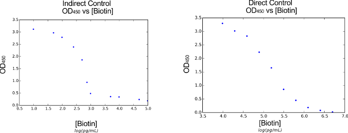
Figure 4: Verification of the Functionalized Material Interface. By exposing our functionalized surface to varying concentrations of biotin, we are able to measure the optical response by measuring OD450 absorbance. These results allow us to generate a calibration curve, linking the concentration of biotin to the optical intensity of the response. Here, we present the biotin vs. optical signal curves for both the indirect (left) and direct (right) functionalized surface schemes. Please click here to view a larger version of this figure.

Figure 5: Engineered Cells Control Material Interface. By utilizing protocol sections 5 or 6, we are able to use the products of induced, engineered cells to chemically modify the functionalized surface. We can monitor these responses optically by measuring OD450. Furthermore, by using the calibration curve developed in Figure 4, we can link the optical intensity of the response to the biotin within the concentration. We present here the different biotin concentrations, measured by our indirect control scheme functionalized surface, for wild-type cells (white), uninduced cells containing the pKE1-lacI-bioB plasmid (orange), and induced cells containing the pKE1-lacI-bioB plasmid (grey). Please click here to view a larger version of this figure.
| Chemical | Final Concentration | Amount |
| 5x M9 salts | 1x | 20 mL |
| 1 M MgSO4 | 2 mM | 200 μL |
| 1 M CaCl2 | 0.1 mM | 10 μL |
| 20% glucose | 0.40% | 2 mL |
| 2% biotin-free Casamino acid | 0.02% | 1 mL |
| DI Water | N/A | 76.8 mL |
Table 1: M9 Media Recipe.
| Name | Primer Sequence | Usage | |
| 1-f | CCGCCGGAATTCTCCCTATCAGTGATAGAGATT | lacI cassette extraction | |
| 1-r | CCGACGTCTCACTGCCCGCTTTCCAGTC | lacI cassette extraction | |
| nBioB1-f | CCCAAGCTTCTGAAATGAGCTGTTGACAATTAATCAT | Ptrc-2 extraction | |
| nBioB1-r | GGGGGGTTCTTTTAATAAAGGTACCGTGTGAAATTGTT | Ptrc-2 extraction | |
| nBioB2-f1 | ACCCCCCTAAGGAGGTCATCATGGCTCACCGCCCACG | bioB extraction | |
| nBioB2-r | TCCCCGCGGTCATAATGCTGCCGCGTTGTAATATTC | bioB extraction | |
| nBioB2-f2 | ACGGTACCTTTATTAAAAGAACCCCCCTAAGGAGGTCATC | Synthetic RBS addition | |
Table 2: List of Primers.
| Step 1 | Step 2 | Step 3 | Step 4 | Step 5 | Step 6 | Step 7 | Step 8 | Step 9 |
| 98°C | 98°C | 70°C | 72°C | 98°C | 60°C | 72°C | 72°C | 4°C |
| 0:30 | 0:10 | 0:30 | 01:00/kb | 0:10 | 0:30 | 01:00/kb | 2:00 | ∞ |
| Repeat 12 times | Repeat 25 times | |||||||
| -1°C / cycle | ||||||||
Table 3: PCR Program.
| Name | Volume |
| Cell Lysate (template) | 10 μL |
| Primer (each) | 0.625 μL (each) |
| 5x Q5 buffer | 5 μL |
| Q5 Polymerase | 0.25 μL |
| dNTP Mix | 0.5 μL |
| DI Water | 6.75 μL |
Table 4: Whole Cell PCR Reaction (25 µL).
| Name | Volume |
| 10x Reaction buffer | 5 µL |
| Enzyme 1 | 1 μL |
| Enzyme 2 | 1 μL |
| Template DNA | 1 µg |
| DI Water | 43 µL – volume of DNA |
Table 5: Restriction Enzyme Digestion Reaction (50 µL).
| Name | Volume |
| DNA | 50 μg vector + X μg insert |
| 10x Ligase Buffer | 1 μL |
| T4 Ligase | 1 μL |
| DI Water | 8 µL – volume of DNA |
Table 6: Ligation Reaction (10 µL).
| Name | Concentration | Notes |
| CaCl2 | 100 mM | |
| Carbeniccilin | 50 mg/mL (1000x) | |
| DTB | 50 μg/mL | |
| IPTG | 0.5 M | |
| SMCC | 20 mg/mL | 2 mg into 100uL DMSO |
| SPDP | 20 mg/mL | 2 mg into 100uL DMSO |
| LC-LC-biotin | 20 mg/mL | 2 mg into 100uL DMSO |
| HRP | 10 mg/mL | In PBS |
| SA (indirect) | 10 mg/mL | In PBS |
| SA (direct) | 0.17 μg/mL | In PBS |
| BSA | 20 mg/mL | In PBS |
| DTT | 100mM | In DI Water |
| EDTA | 5 mM | 18.6 mg into 10 mL PBS |
| Casein | 0.50% | In PBS |
| Tween 80 | 20% | In DI Water |
| Tween 80 in PBS | 0.05% | |
| Sodium Acetate | 50 mM | In DI Water, Adjust to 5.1 pH using 3 M HCl |
| TMB | 1% | In DMSO |
| H2O2 | 3% | In DI Water |
| H2SO4 | 2 M | In DI Water |
Table 7: List of Reagent Solutions.
Subscription Required. Please recommend JoVE to your librarian.
Discussion
We have presented a new strategy for interfacing engineered living cells with a functionalized material surface. This was accomplished by developing a cell line capable of synthesizing elevated levels of biotin when induced with IPTG. The elevated levels of biotin may then be used to modify the functionalized surface. The protocols detailed how to engineer the E. coli cell line and how to create two different functionalized surfaces.
Critical steps in this protocol occur throughout the construction of the engineered cell line. To avoid downstream issues, characterizing the engineered cell strains with both growth curves (Figure 2) and fluorescent response (Figure 3) is encouraged. Should procedural issues arise, other molecular cloning strategies, such as PCR extraction and Gibson assembly14, may be substituted for steps where appropriate. For optimizing the biotin yield of the engineered cell line, it is crucial to ensure that a sufficient amount of DTB is provided to the cells. In our studies, we found that 200 ng/mL DTB elicited a substantial and statistically significant increase in biotin production when cells were induced with IPTG. Additionally, successful conjugation of BSA-Biotin, SA-HRP, and Biotin-HRP is crucial for effectively performing and monitoring the indirect and direct control schemes. Take care to avoid unnecessary exposure to light and allow the conjugates to incubate overnight at 4 °C to ensure an effective conjugate is formed.
Our protocol offers advantages over alternative methods15 due to its ability to detect small quantities of biotin that are biologically relevant (pg/mL scale) compared to commercially available biotin detection kits, such as those based on 4'-hydroxyazobenzene-2-carboxylic acid competitive binding strategies. Although using the streptavidin-biotin system is common in biotechnology16,17, our system's ability to respond to small quantities of biotin allows us to directly link our genetically engineered cell line with the functionalized surface.
One potential limitation of our protocol is the resulting dynamic range of biotin detection. In the indirect and direct control schemes, we are able to detect biotin between 102-103 and 104-106 pg/mL, respectively (Figure 4). Fortunately, the low range of the indirect control scheme allows us to readily detect biotin production from engineered cells. However, the tight band of the indirect control dynamic range limits its ability to sense large changes (100-fold) in biotin concentrations. Altering the dynamic range for both the indirect and direct control schemes would require additional engineering. However, if detection of cell-produced biotin is an issue, preparing dilutions of the biotin supernatant in step 4.6 should allow the researcher to target the dynamic range of the indirect control scheme (Figure 5). We found that a 1:5 dilution of the supernatant allowed us to target the indirect control scheme's dynamic range effectively. This dilution strategy should alleviate the need to modify the dynamic range directly.
The two-part, cell-material system presented here allows engineered cells to modify the composition of a functionalized surface. Dynamic, living cells can interpret their chemical surroundings to produce a genetic response. By engineering this genetic response to increase biotin production, we can endow engineered living cells with the ability to control and manipulate a functionalized surface. By following the protocols presented, engineered cells are able to act as dynamic sensors, capable of reading, processing, and recording the conditions around them via functionalized interfaces. This technology could impact fields ranging from molecular medicine to analyte detection for environmental remediation.
Subscription Required. Please recommend JoVE to your librarian.
Disclosures
The authors have nothing to disclose.
Acknowledgments
The authors gratefully acknowledge support from award FA9550-13-1-0108 from the Air Force Office of Scientific Research of the USA. The authors additionally acknowledge support from award N00014-15-1-2502 from the Office of Naval Research of the USA, funding from the Institute for Critical Technology and Applied Science at Virginia Polytechnic Institute and State University, and from the National Science Foundation Graduate Research Fellowship Program, award number 1607310.
Materials
| Name | Company | Catalog Number | Comments |
| LB Broth, Miller | Fisher Scientific | 12-795-027 | |
| Agar | Fisher Scientific | BP9744500 | |
| Carbenicillin | Fisher Scientific | BP26481 | |
| M9, Minimimal Salts, 5x | Sigma-Aldrich | M6030 | |
| Casamino Acids | Fisher Scientific | BP1424-100 | |
| Magnesium Sulfate, Anhydrous | Fisher Scientific | M65-500 | |
| Calcium Chloride, Dihydrate | Fisher Scientific | C79-500 | |
| Dextrose (D-Glucose), Anhydrous | Fisher Scientific | D16-1 | |
| NEB Turbo Cell Line | New England Biolabs | C2984l | |
| Oligonucleotide Primers | Thermo Fisher Scientific | N/A | 25N synthesis, DSL purification |
| Q5 High-Fidelity Polymerase | New England Biolabs | M0491S | |
| Q5 Reaction Buffer | New England Biolabs | B9027S | |
| dNTP Solution Mix | New England Biolabs | N0447S | |
| Agarose | Bioexpress | E-3120-125 | |
| Ethidium Bromide, 1% | Fisher Scientific | BP1302-10 | |
| Gel Extraction Kits | Epoch Biolabs | 2260250 | |
| GenCatch Plasmid DNA Miniprep Kit | Epoch Biolabs | 2160250 | |
| AatII | New England Biolabs | R0117S | |
| SacII | New England Biolabs | R0157S | |
| HindIII-HF | New England Biolabs | R3104S | |
| EcoRI-HF | New England Biolabs | R3101S | |
| Cutsmart Buffer | New England Biolabs | B7204S | |
| T4 DNA Ligase | New England Biolabs | M0202S | |
| T4 DNA Ligase Reaction Buffer | New England Biolabs | B0202S | |
| ColiRolle Glass Plating Beads | EMD Millipore | 7101-3 | |
| Glycerol | Fisher Scientific | BP229-1 | |
| Isopropyl β-D-1-thiogalactopyranoside (IPTG) | Fisher Scientific | BP1755-10 | |
| NHS-Desthiobiotin (DTB) | Thermo Fisher Scientific | 16129 | |
| Succinimidyl Trans-4-(maleimidylmethyl) Cyclohexane-1-Carboxylate (SMCC) | Thermo Fisher Scientific | S1534 | |
| Dimethyl Sulfoxide (DMSO) | Fisher Scientific | BP231-100 | |
| Succinimidyl 3-(2-pyridyldithio) Propionate (SPDP) | Thermo Fisher Scientific | S1531 | |
| NHS-LC-LC-biotin | Thermo Fisher Scientific | 21343 | |
| Horseradish Peroxidase (HRP) | Thermo Fisher Scientific | 31490 | |
| Phosphate Buffered Saline (PBS), 10x Solution | Fisher Scientific | BP399500 | |
| Streptavidin (SA) | Thermo Fisher Scientific | 21145 | |
| Bovine Serum Albumin (BSA) | Fisher Scientific | BP1600-100 | |
| Dithiothreitol (DTT) | Fisher Scientific | BP172-5 | |
| Ethylenediaminetetaacetic acid (EDTA) | Fisher Scientific | S311-500 | |
| Tween 80 | Fisher Scientific | T164-500 | |
| Hydrogen Peroxide | Fisher Scientific | H325-4 | |
| 3, 3', 5, 5'-tetramethylbenzidine (TMB) | Fisher Scientific | AC229280050 | |
| Vivaspin 500 Centrifugal Concentrators | Viva Products | VS0192 | |
| Sodium Acetate, Anhydrous | Fisher Scientific | BP333-500 | |
| 96-Well Polystyrene Plates | Thermo Fisher Scientific | 266120 |
References
- Zhang, R., Heyde, K. C., Scott, F. Y., Paek, S. -H., Ruder, W. C. Programming Surface Chemistry with Engineered Cells. ACS Synth. Biol. , (2016).
- Zhou, X., et al. Reduced graphene oxide films used as matrix of MALDI-TOF-MS for detection of octachlorodibenzo-p-dioxin. Chem. Commun. 46, 6974-6976 (2010).
- Pardee, K., et al. Low-Cost Detection of Zika Virus Using Programmable Biomolecular Components. Cell. 165, 1255-1266 (2016).
- Bähring, S., et al. Design and Sensing Properties of a Self-Assembled Supramolecular Oligomer. Chem. Eur. J. 22, 1958-1967 (2016).
- Nicolau Jr, D. V., Armitage, J. P., Maini, P. K. Directional persistence and the optimality of run-and-tumble chemotaxis. Comp. Biol. Chem. 33, 269-274 (2009).
- Du, J., Shao, Z., Zhao, H. Engineering microbial factories for synthesis of value-added products. J. Ind. Microbiol. Biotechnol. 38, 873-890 (2011).
- Kim, H., Kim, M. J. Electric Field Control of Bacteria-Powered Microrobots Using a Static Obstacle Avoidance Algorithm. IEEE Trans. Rob. 32, 125-137 (2016).
- Gardner, T. S., Cantor, C. R., Collins, J. J. Construction of a genetic toggle switch in Escherichia coli. Nature. 403, 339-342 (2000).
- Heyde, K. C., Ruder, W. C. Exploring Host-Microbiome Interactions using an in Silico Model of Biomimetic Robots and Engineered Living Cells. Sci. Rep. 5, 11988 (2015).
- Rice, M. K., Ruder, W. C. Creating biological nanomaterials using synthetic biology. Sci. Tech. Adv. Mater. 15, 014401 (2014).
- Green, N. M. Avidin. 3. The nature of the biotin-binding site. Biochem. J. 89, 599-609 (1963).
- Mesulam, M. M. Tetramethyl benzidine for horseradish peroxidase neurohistochemistry: a non-carcinogenic blue reaction product with superior sensitivity for visualizing neural afferents and efferents. J Histochem. Cytochem. 26, 106-117 (1978).
- Litcofsky, K. D., Afeyan, R. B., Krom, R. J., Khalil, A. S., Collins, J. J. Iterative plug-and-play methodology for constructing and modifying synthetic gene networks. Nat. Meth. 9, 1077-1080 (2012).
- Gibson, D. G., et al. Complete Chemical Synthesis, Assembly, and Cloning of a Mycoplasma genitalium Genome. Science. 319, 1215-1220 (2008).
- Diamandis, E. P., Christopoulos, T. K. The biotin-(strept)avidin system: principles and applications in biotechnology. Clin. Chem. 37, 625-636 (1991).
- Nerurkar, L. S., Namba, M., Brashears, G., Jacob,, Lee, A. J., Sever, Y. J., L, J. Rapid detection of herpes simplex virus in clinical specimens by use of capture biotin-streptavidin enzyme-linked immunosorbent assay. J. Clin. Micro. 20, 109-114 (1984).
- Cui, Y., Wei, Q., Park, H., Lieber, C. M. Nanowire Nanosensors for Highly Sensitive and Selective Detection of Biological and Chemical Species. Science. 293, 1289-1292 (2001).
