This protocol describes a method for exposing rodents to electronic cigarette vapor (E-vapor) and cigarette smoke. Exposure chambers are constructed by modifying anesthesia chambers with an automated pumping system that delivers E-vapor or cigarette smoke to rodents. This system can easily be modified to accommodate many experimental endpoints.
Method Article
Comparing the Effects of Electronic Cigarette Vapor and Cigarette Smoke in a Novel In Vivo Exposure System
Opens in a new tab
In This Article
Summary
Loading...
$$\rightleftharpoonup{xx}$$
$$\longleftharp{xx}$$,
$$\longrightharp{xx}$$,
Abstract
Loading...
$$\rightleftharpoonup{xx}$$
$$\longleftharp{xx}$$,
$$\longrightharp{xx}$$,
Electronic cigarettes (E-cigarettes) are being widely used, and growing in popularity. It is estimated that more than 9 million adults use them regularly. The potential adverse health effects of electronic cigarette vapor (E-vapor) exposure are poorly defined. While several animal models of E-vapor exposure have been developed, few models expose rodents to clinically relevant quantities of nicotine and make direct comparisons to cigarette smoke within the same exposure system. Here, we present a method for constructing and operating an E-vapor chamber and cigarette smoke chamber. The chambers are constructed by outfitting anesthesia chambers with a computer controlled pumping system that delivers consistent amounts of E-vapor or cigarette smoke to rodents. Nicotine exposure is measured indirectly by quantifying pre and post-exposure serum cotinine levels. This exposure system can be modified to accommodate various types of E-cigarettes and tobacco cigarettes, and can be used to compare the effects of E-vapor and cigarette smoke in vivo.
Introduction
Loading...
$$\rightleftharpoonup{xx}$$
$$\longleftharp{xx}$$,
$$\longrightharp{xx}$$,
Since entering the US market in 2004, electronic cigarettes (E-cigarettes) have expanded into a billion-dollar industry, and it is estimated that nearly 9 million adults use them regularly1. In 2014 and 2015, more high school students had used E-cigarettes than conventional cigarettes2. The growing number of E-cigarettes users has spawned a research effort to evaluate their potential adverse health effects.
E-cigarettes generate a vapor (dubbed "E-vapor") by heating a viscous solution that typically contains a mixture of water, polyethylene glycol or vegetable glycerin, nicotine, and flavorings3,4. It has been shown that E-vapor contains several harmful compounds including Reactive Oxygen Species (ROS), nicotine, various aldehydes, and polycyclic aromatic hydrocarbons5,6. Many of these compounds are formed during the vaporization process of E-liquid prior to inhalation7. Notably, several of these harmful compounds are also present in cigarette smoke, raising concern that E-cigarettes use may have similar adverse health consequences7.
There is little consensus on the health effects of E-cigarettes. To address this, several animal models of E-vapor exposure have been developed (Table 1). These models employ a variety of methods such as whole-body E-vapor exposure and mechanical ventilation. While current models have provided insightful data, few make direct comparisons to cigarette smoke within the same exposure system (Table 1). Additionally, while several human studies have shown E-cigarettes users and cigarette smokers to have serum cotinine levels between 30-200 ng/mL, many models of E-vapor and cigarette smoke exposure fall outside this range8,9,10,11,12.
Herein we present a method for comparing the effects of cigarette smoke and E-vapor exposure in vivo that yields serum cotinine levels similar to human studies.
Access restricted. Please log in or start a trial to view this content.
Protocol
Loading...
$$\rightleftharpoonup{xx}$$
$$\longleftharp{xx}$$,
$$\longrightharp{xx}$$,
The following protocol has been performed under the guidance and approval of the University of Michigan Institutional Animal Care and Use Committee (IACUC).
1. Electronic Cigarette-vapor Chamber Assembly
NOTE: The complete chamber should be placed in a fume hood during use. The chamber here was housed in a temperature controlled and filtered laboratory environment. Investigators may elect to monitor such aspects of the system to ensure consistency of the room air quality. As an option, covering the monitors with a metal cage can prevent rodent tampering while allowing the monitors to sample the interior chamber environment.
- Acquire an anesthesia chamber with air tight removable lid with volume of 20 L.
- Using a jig saw fitted with a blade appropriate for cutting the material, cut a 10.2 cm diameter hole in the lid of the chamber approximately 7.6 cm from the back edge of the chamber.
- Insert the adjustable vent into the hole and mount into place with any caulk adhesive.
NOTE: Ensure that the adhesive caulk is not accessible to the rodents in the chamber, as they may chew the caulk. To prevent this possible issue, apply the caulk to the outside of the chamber wall to mount the vent. - Cut silicone tubing into two 15 cm segments, and attach ends to either side of a T-connector.
NOTE: Silicone tubing has the potential to react with some components of e-vapor or cigarette smoke. Thus, investigators may consider using non-reactive tubing. - Thread both of the silicone tubes through premade holes near the front of the chamber lid so that the T-connector is inside the chamber. Ensure that the tubing is secured to the lid with either adhesive caulk or electrical tape.
- Connect the free ends of the silicone tubing to the output ends of two micro air pumps. Pumps should be mounted to the lid of the chamber with double-sided adhesive tape or caulk.
NOTE: The length of tubing connected to the output end of the pump should be short to limit the amount of vapor collection on the inside surface of the tubing during use. - With a new silicone tube, attach one end to the input side of one of the air pumps (Pump A in Figure 1), and cut this tube to approximately 4 cm in length. This is where the electronic cigarette will be inserted during chamber use. Ensure that the diameter of the tube allows for a snug fit around the end of the e-cig.
- With a new silicone tube, attach one end to the input side of the other air pump (Pump B in Figure 1). This pump will introduce room air into the chamber. As such, the end of the tube must be placed outside the fume hood. The length of this tube is not critical, but should be as short as possible to limit airflow resistance.
- Inside the chamber attach two small hooks with double-sided adhesive to hold oxygen and carbon monoxide gas monitors.
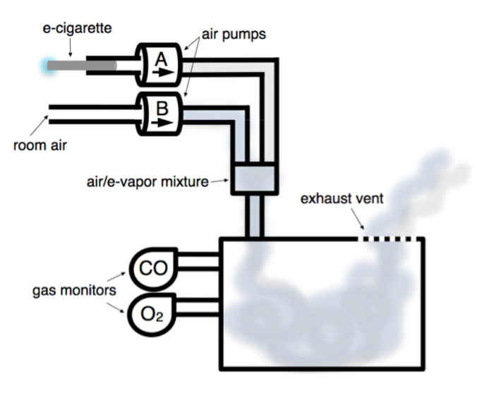
Figure 1. Schematic of Electronic Cigarette-vapor Chamber.
Chamber is housed in fume hood (not shown). Room air pump (Pump B) introduces room air from outside the fume hood into chamber continuously at 2 L/min. E-cig pump (Pump A) puffs 133 mL of E-vapor over 4 s, with a 30 s rest interval. E-vapor and room air mix prior to being pumped into chamber. Gas monitors continuously measure carbon monoxide (CO) and oxygen (O2) concentrations inside the chamber. E-vapor is exhausted passively through vent into fume hood. Please click here to view a larger version of this figure.
2. Cigarette Smoke-chamber Assembly
NOTE: Virtually any brand of cigarette can be used with this system, however standardized research cigarettes such as the University of Kentucky 1R6F Research Cigarette are cost-effective, reliable, and best for this application.
- Follow steps 1.1 - 1.6, & step 1.9.
- With a new silicone tube, attach one end to the cigarette lighting device, and the other end to the input side of the air pump (Pump A in Figure 2). The cigarette lighting device should be placed inside the fume hood and outside the chamber during use.
Note: Construction of the cigarette lighting device requires knowledge of metal fabrication and electrical engineering. While a step-by-step guide to construction will not be given here, see supplementary materials for plans. - With a new silicone tube, attach one end to the other air pump (Pump B in Figure 2). This pump will introduce room air into the chamber, thus the end of the tube must be placed outside the fume hood.
- Cut several 5 mm wide vertical slits in the front wall of the chamber, and mount a computer fan on the outside of the chamber so that it covers this opening. Ensure that the front of the fan is facing towards the chamber such that the fan will blow air into the chamber through this opening.
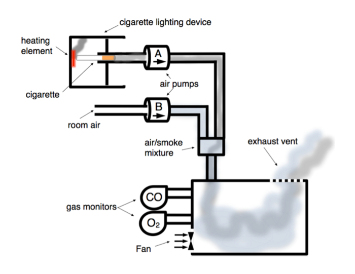
Figure 2. Schematic of Cigarette-smoke Chamber.
Room air pump (Pump B) introduces room air from outside the fume hood into chamber continuously at 2 L/min. Pump A draws on lit cigarette for 40 s with rate of 2 L/min, and 20 s later the computer fan evacuates the chamber over 3 min. Smoke and room air mix prior to being pumped into chamber. Gas monitors continuously measure carbon monoxide (CO) and oxygen (O2) chamber concentrations. Smoke is exhausted through vent into fume hood. Please click here to view a larger version of this figure.
3. Microcontroller Assembly and Software
- Control the pumping system of the E-cigarette vapor chamber and cigarette smoke chamber by separate microcontrollers. Download the microcontroller software and upload the operating codes provided in the Supplementary Materials. The electronic cigarette vapor code will run the room air pump continuously and activate the E-cigarette pump for a 4 s duration every 30 s. The cigarette smoke code will run the room air pump continuously, activate the cigarette pump for 40 s, and activate the computer fan 20 s after the cigarette pump has stopped. The fan will shut off after running for 3 min.
Note: The timing of the pumps and fan can be adjusted as needed. Reference manufacturer instructions on how to upload relevant codes to the microcontroller. - To assemble the microcontroller, connect zip wires, diodes, resisters, and capacitors to the bread board as depicted in Figure 3 and attach alligator-clip wires to the corresponding air pumps (and computer fan for cigarette smoke chamber). House the microcontroller outside of the fume hood if possible.
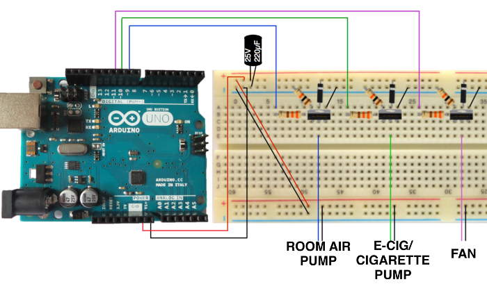
Figure 3. Schematic of Microcontroller.
Schematic of microcontroller and bread board to operate timing of air pumps and fan. Please click here to view a larger version of this figure.
4. Animals
- Use adult rats weighing 450 - 520 g.
- Group rats according to exposure type (e.g., electronic cigarette, cigarette smoke, room air pumped into chamber).
- At this time prior to exposure, collect 500 µL of blood in EDTA coated tubes from tail vein using syringe to measure baseline serum cotinine concentration.
- Spin down blood samples at 20,000 x g for 30 min at 4 ˚C and collect serum. Ensure that samples are chilled on ice throughout this process.
- Following the manufacturer protocol, assay for cotinine in the serum samples collected. Samples may also be stored at -80 ˚C for later use.
5. Operating the Electronic cigarette Chamber
- Clean the inside of the chamber with 70% ethanol, then with deionized water, and let air dry until the chamber is completely dry (or about 30 min).
- Calibrate gas monitors and mount entire monitor on the wall inside the chamber.
- Place rats inside the chamber. Note that up to three animals can be exposed simultaneously.
- Ensure the E-cigarette is fully charged with adequate E-liquid and insert the E-cigarette into input tube. It is critical to ensure that the E-cigarette battery and E-liquid levels are adequate throughout the duration of the 90-min exposure.
- Turn the air pumps on, and start the timer.
- During exposure observe the gas monitors to ensure chamber contains >20% O2 and 0 ppm CO.
Note: If oxygen levels fall, the chamber may not be well ventilated or the oxygen monitor may not be appropriately calibrated. - Once the exposure time has reached 90 min, remove the E-cigarette and continue to run the gas pumps to vent the remaining vapor. Additionally, the top of the chamber can be lifted to hasten ventilation.
- Once the vapor has cleared, remove the rats and clean the chamber.
- Collect 500 µL blood from tail vein from each rat approximately 1 h after exposure at the conclusion of the experimental protocol.
- Follow steps 4.4 - 4.5 to isolate serum and assay for cotinine.
6. Operating the Tobacco Cigarette Chamber
- Follow steps 5.1 - 5.3.
- Insert cigarette into cigarette lighting device, with the end of the cigarette against the heating elements.
- Turn on the cigarette lighting device until cigarette butt begins to smolder (about 5 s).
- Once the cigarette is lit, turn on the pumping system, start the timer, and observe the cigarette burn to completion (about 40 s).
- Once the cigarette has burned, carefully remove the spent cigarette from the cigarette lighting device with forceps.
- Ensure that CO levels do not rise above 1000 ppm and O2 levels do not fall below 20%. Computer fan timing and duration is critical in preventing carbon monoxide accumulation.
- After 4 min turn the pumping system off and return to step 6.2 until rats are exposed to tobacco smoke for 90 min (or approximately 23 cigarettes).
NOTE: Carbon monoxide levels 4 min following cigarette burning should fall below 400 ppm, otherwise carbon monoxide may begin to accumulate in chamber. - When exposure is complete, continue to leave the pumping system on to ventilate residual smoke. When carbon monoxide falls below 100 ppm remove rats from chamber. This should take 5 - 10 min.
- Remove rats and clean the chamber.
- Collect 500 µL blood from tail vein approximately 1 h after exposure at the conclusion of the experimental protocol as with the E-cigarettes.
- Follow steps 4.4 - 4.5 to isolate serum and assay for cotinine.
Access restricted. Please log in or start a trial to view this content.
Results
Loading...
$$\rightleftharpoonup{xx}$$
$$\longleftharp{xx}$$,
$$\longrightharp{xx}$$,
Carbon monoxide and oxygen monitoring
Oxygen concentrations did not fall below 20% during e-vapor exposure and CO concentrations remained undetectable throughout exposure. Gas monitors during cigarette smoke exposure indicated that oxygen concentration remained above 20%. Carbon monoxide concentrations did not exceed 1,000 ppm (Figure 4).
Access restricted. Please log in or start a trial to view this content.
Discussion
Loading...
$$\rightleftharpoonup{xx}$$
$$\longleftharp{xx}$$,
$$\longrightharp{xx}$$,
Here we describe a method for constructing chambers that expose rodents to E-vapor and cigarette smoke in a controlled fashion (Figure 6). Construction of the E-cigarette chamber is relatively simple and inexpensive compared to commercial exposure systems14,15,16. The parts and tools required to build the chamber are readily available from commercial suppliers online. Similarly, constructing the cigarette smoke ...
Access restricted. Please log in or start a trial to view this content.
Disclosures
Loading...
$$\rightleftharpoonup{xx}$$
$$\longleftharp{xx}$$,
$$\longrightharp{xx}$$,
The authors have nothing to disclose.
Acknowledgements
Loading...
$$\rightleftharpoonup{xx}$$
$$\longleftharp{xx}$$,
$$\longrightharp{xx}$$,
This research was made possible by the Aortic Research Grant (University of Michigan) to Dr. Eliason. The authors would also like to acknowledge Nick Scott at the University of Michigan Plant Operations Sign and Graphics Department for assisting with the design and assembly of the cigarette lighting device.
Access restricted. Please log in or start a trial to view this content.
Materials
| Name | Company | Catalog Number | Comments |
|---|---|---|---|
| blu PLUS Rechargeable Kit | blu eCigs | N/A | |
| 1R6F Reference Cigarettes | Center for Tob Ref Prod UK | N/A | |
| Lexan Anesthesia Chamber 20 L | Jorgensen Laboratories | JOR265 | |
| Arduino UNO | Arduino | 2877 | |
| Diode Rectifier - 1 A; 50 V | Spark Fun | COM-08589 | |
| Resistor 10 KOhm 1/6th W PTH - 20 pack | Spark Fun | COM-11508 | |
| Electrolytic Decoupling Capacitors - 100 uF/25 V | Spark Fun | COM-00096 | |
| Solderless Plug-in BreadBoard | BusBoard Prototype Systems | BB400 | |
| Alligator-Clip Wires | BusBoard Prototype Systems | CA-M-20 | |
| ZipWire | BusBoard Prototype Systems | ZW-MM-10 | |
| Standard Fan 80 ST2 | Cooler Master | R4-S8R-20AK-GP | |
| ARIC 4" adjustable vent | Bestlouver | N/A | |
| ToxiPro Carbon Monoxide (CO) Monitor | Honeywell Analytics | 54-00-10316 | |
| ToxiPro Oxygen (O2) Monitor | Honeywell Analytics | 54-45-90-VD | |
| ToxiPro IQ Express Docking Station | Honeywell/Sperian Biosystems | 54-46-9100 | |
| Command Wall Hook Small Wire 6-Pack | 3M | N/A | |
| Micro Water/Air Pump | Xiamen Conjoin Electronics | CJWP40-A12A1 | |
| 1/4" Silicon Tubing | NewAge | 2801470-100 | |
| T Connector | Bel-Art Scienceware | F196060000 | |
| Plastic Whole Blood tube with spray-coated K2EDTA | Becton, Dickinson and Company | 367841 | |
| Cotinine ELISA kit | Calbiotech | CO096D |
References
Loading...
$$\rightleftharpoonup{xx}$$
$$\longleftharp{xx}$$,
$$\longrightharp{xx}$$,
- Schoenborn, C. A., Gindi, R. M. Electronic Cigarette Use Among Adults: United States, 2014 Key findings. NCHS. , (2014).
- Singh, T. Tobacco Use Among Middle and High School Students - United States, 2011-2015. MMWR. 65 (14), 361-367 (2016).
- Flora, J. W. Characterization of potential impurities and degradation products in electronic cigarette formulations and aerosols. Regul. Toxicol. Pharmacol: RTP. 74, 1-11 (2016).
- Tierney, P. A., Karpinski, C. D., Brown, J. E., Luo, W., Pankow, J. F. Flavour chemicals in electronic cigarette fluids. Tob. Control. , (2015).
- Sleiman, M. Emissions from Electronic Cigarettes: Key Parameters Affecting the Release of Harmful Chemicals. Environ. Sci. Technol. 50 (17), 9644-9651 (2016).
- Hwang, J. H. Electronic cigarette inhalation alters innate immunity and airway cytokines while increasing the virulence of colonizing bacteria. Int J Mol Med (Berlin, Germany). 94 (6), 667-679 (2016).
- Cheng, T. Chemical evaluation of electronic cigarettes. Tob Control. 23, 11-18 (2014).
- Etter, J. -F. A longitudinal study of cotinine in long-term daily users of e-cigarettes. Drug Alcohol Depend. 160, 218-221 (2016).
- Etter, J. -F. Levels of saliva cotinine in electronic cigarette users. Addiction. 109 (5), 825-829 (2014).
- Marsot, A., Simon, N. Nicotine and Cotinine Levels With Electronic Cigarette: A Review. Int. J. Toxicol. 35 (2), 179-185 (2016).
- Flouris, A. D. Acute impact of active and passive electronic cigarette smoking on serum cotinine and lung function. Inhal. Toxicol. 25 (2), 91-101 (2013).
- Bot, M. Plasma cotinine levels in cigarette smokers: impact of mental health and other correlates. Eur Addict Res. 20 (4), 183-191 (2014).
- Zhu, S. -H. Four hundred and sixty brands of e-cigarettes and counting: implications for product regulation. Tob. Control. 23, Suppl 3. 3-9 (2014).
- CH TECHNOLOGIES. Single Cigarette Smoking Machine SCSM-STEP. , Available from: http://chtechusa.com/products_tag_smoke_single-cigarette-CSM-SCSM.php (2016).
- SCIREQ. inExpose. , Available from: http://www.scireq.com/inexpose (2016).
- TSE Systems. Cigarette Smoke Generators. , Available from: http://www.tse-systems.com/products/inhalation/aerosol-vapor-generation/cigarette-smoke.htm (2016).
Access restricted. Please log in or start a trial to view this content.
Reprints and Permissions
Request permission to reuse the text or figures of this JoVE article
Request Permission