Here, we present a method of the spectroscopic characterization of organic molecules by means of time-resolved photoluminescence spectroscopy on the nanosecond-to-millisecond timescale in oxygen-free conditions. Methods to efficiently remove oxygen from the samples and, thus, limit luminescence quenching are also described.
Method Article
Time-resolved Photophysical Characterization of Triplet-harvesting Organic Compounds at an Oxygen-free Environment Using an iCCD Camera
Opens in a new tab
In This Article
Summary
Loading...
$$\rightleftharpoonup{xx}$$
$$\longleftharp{xx}$$,
$$\longrightharp{xx}$$,
Abstract
Loading...
$$\rightleftharpoonup{xx}$$
$$\longleftharp{xx}$$,
$$\longrightharp{xx}$$,
Here, we present a sensible method of the acquisition and analysis of time-resolved photoluminescence using an ultrafast iCCD camera. This system enables the acquisition of photoluminescence spectra covering the time regime from nanoseconds up to 0.1 s. This enables us to follow the changes in the intensity (decay) and emission of the spectra over time. Using this method, it is possible to study diverse photophysical phenomena, such as the emission of phosphorescence, and the contributions of prompt and delayed fluorescence in molecules showing thermally activated delayed fluorescence (TADF). Remarkably, all spectra and decays are obtained in a single experiment. This can be done for solids (thin film, powder, crystal) and liquid samples, where the only limitations are the spectral sensitivity of the camera and the excitation wavelength (532 nm, 355 nm, 337 nm, and 266 nm). This technique is, thus, very important when investigating the excited state dynamics in organic emitters for their application in organic light-emitting diodes and other areas where triplet harvesting is of paramount importance. Since triplet states are strongly quenched by oxygen, emitters with efficient TADF luminescence, or those showing room temperature phosphorescence (RTP), must be correctly prepared in order to remove any dissolved oxygen from solutions and films. Otherwise, no long-lived emission will be observed. The method of degassing solid samples as presented in this work is basic and simple, but the degassing of liquid samples creates additional difficulties and is particularly interesting. A method of minimizing solvent loss and changing the sample concentration, while still enabling to remove oxygen in a very efficient and a repeatable manner, is presented in this work.
Introduction
Loading...
$$\rightleftharpoonup{xx}$$
$$\longleftharp{xx}$$,
$$\longrightharp{xx}$$,
Time-resolved spectroscopy is an essential tool in the studies of novel materials for the application of organic light-emitting diodes (OLED)1,2,3. These techniques are especially important for the latest generations of OLED emitters [i.e., as thermally activated delayed fluorescence (TADF)4,5,6,7,8 or phosphorescent9,10,11 molecules], where photoluminescence processes can be observed in a broad timescale (up to seconds). Interestingly, such techniques can also be used to investigate electroluminescence in devices, over suitable time regimes12,13. The methods described above are, in general, focused on following time-dependent properties that involve photoluminescence signals such as the decay lifetime, the shape and energy of the emission spectra, and its dependence upon temperature or other factors.
Overall, the most popular method of time-resolved spectroscopy is time-correlated single photon counting (TCSPC) or its modifications, such as multichannel TCSPC. This method is especially suited to follow fast decays with a very high accuracy, usually on the nanosecond timescale. However, it has a major disadvantage, as it does not allow following the changes in the photoluminescence spectrum in an easy way. This is resolved using streak cameras14,15. However, both methods are not suited to follow long-lived luminescence decays. In this case, time-gated methods and multichannel scaling are the methods of election.
In this work, we discuss the time-gated acquisition of photoluminescence signals in a time range from less than a nanosecond up to 0.1 - 1 s in a single experiment16,17,18. Moreover, the quality of the spectra is excellent due to the high sensitivity of the detector that is used (an iCCD camera). This allows the observation of very fine changes in the emission spectrum and the investigation of the excited state dynamics in detail, identifying the emission of different excited species in one molecular system. The versatility of this equipment has been confirmed by several recent publications19,20,21,22,23,24,25,26. The excitation source is either an Nd:YAG laser with a 10 Hz repetition rate, providing a set of harmonics (266 nm, 355 nm, and 532 nm) or a nitrogen laser (337 nm) of a changeable repetition rate between 1 - 30 Hz.
The principle of the work of iCCD cameras is based on the image intensifier, which not only intensifies the incoming light but also works as a shutter (gate). The intensifier consists of a photocathode that is sensitive to a specific spectral range [i.e., ultraviolet (UV), visible, red, and near-infrared (NIR)], a micro-channel plate (MCP), and a phosphor. By changing the photocathode, it is possible to adapt the camera to a specific use. The photocathode converts incoming photons into photoelectrons that are multiplied in the MCP and then hit the phosphor screen generating photons. These photons, through a system of lenses, are focused onto a CCD chip and are converted into an electrical signal. For further details, please refer to the manufacturer's webpage27.
To collect emission spectra throughout the range from 1 ns to 100 ms with sufficient signal-to-noise ratio, the integration (exposure) time increases exponentially along with exponentially increasing the time delay. This is dictated by the properties of the photoluminescence decay, which follows exponential laws in most systems.
The method described here can be applied to several sample sizes and forms, including those with an uneven surface, powders, or small crystals19. The sample holder is easily adapted to support several different cuvettes, including standard and degassing cuvettes or flow cuvettes. All samples with photoluminescence in a range of 350 - 750 nm can be investigated by this equipment. The system is also equipped with a liquid nitrogen cryostat to perform temperature-dependent measurements of solid and liquid samples down to 77 K and a closed-cycle helium cryostat to perform measurements of solid samples down to 15 K. This allows studying such phenomena like TADF and phosphorescence. In summary, any compound or any kind of sample that emits photoluminescence in the specified region and time range and which absorbs the excitation laser light can be investigated in this equipment.
The removal of molecular oxygen is a particularly important issue in the investigation of the photophysics of molecules with a long-lived emission. Therefore, an experimental procedure of degassing samples (solutions and films) is also described in detail here. Quenching by oxygen affects long-lived luminescence and is a major problem in the investigation of delayed fluorescence and phosphorescence. However, this quenching effect also facilitates the investigation of the contribution of triplet excited states to the overall luminescence. This is accounted for measuring the photoluminescence intensity ratio of a degassed solution/film to air-saturated conditions17,23. As triplets are quenched by oxygen, the degassing-to-air emission ratio gives direct information about the contribution of the long-lived states that are responsible for the long-lived emissions (and so delayed fluorescence or phosphorescence). This can then be used to extract information about the yields of triplet formation in organic TADF emitters. Molecular oxygen exists in a triplet ground state as a biradical. Upon absorption of energy of ca. 1 eV, triplet oxygen undergoes a transition to a singlet excited state. Typically, excited state molecules have an energy of singlet and triplet higher than 1 eV. This energy can, therefore, be transferred to oxygen upon collision. As a result, the molecule returns to a ground state or undergoes intersystem crossing.
One of the most popular methods of degassing solutions is bubbling them with a neutral gas with no oxygen content, usually very pure nitrogen or argon. This technique is very helpful in different research areas (i.e., electrochemistry or photophysics)28,29,30,31. However, while this is a simple procedure and even effective for most purposes, simply purging a solution with a neutral gas is not always the most adequate way, as removing oxygen in trace amounts is almost impossible by this method. Moreover, severe solvent loss can occur due to its volatility, which may lead to changes in the concentration of the sample under study. However, this can be prevented by a saturation of the gas with the solvent used in the solution.
The technique described here is based on a different principle. It allows reducing solvent losses to a minimum and provides repeatable levels of oxygen removal. The technique requires special, usually home-made degassing cuvettes comprising a quartz cell for the acquisition of the luminescence signal - fluorescence or phosphorescence - and a small glass flask with a spherical shape for freezing/unfreezing, and a valve. Degassing is performed under repeating freezing/unfreezing cycles. Oxygen extraction is performed in a vacuum, with the sample in the flask compartment, and while the sample is frozen, followed by letting the sample equilibrate at room temperature, with the vacuum valve closed - during this period, solution melting occurs, and the oxygen dissolved in the liquid phase is released. This requires using the cuvette itself, a regular rotary vacuum pump, and a liquid nitrogen source for cooling. The method can be used with a variety of solvents, preferably those of a low melting point such as toluene, ethanol, methylcyclohexane, 2-methyltetrahydrofuran. Degassing solutions using this technique is fast, efficient, and reliable.
Figure 1 shows with a scheme how TADF and RTP luminescence in organic molecules is generated. Prompt fluorescence, delayed fluorescence, and phosphorescence can all be recorded with the same measurement setup. With this technique, not only luminescence decays but also time-resolved emission spectra can be recorded. This enables the characterization of the molecular system and the facile identification of RTP and TADF emitters. As Figure 3 shows, a TADF emitter will normally show the same emission spectrum over the whole decay, while an RTP emitter shows a short-lived fluorescence and a long-lived phosphorescence that differ in the emission spectra.
Protocol
Loading...
$$\rightleftharpoonup{xx}$$
$$\longleftharp{xx}$$,
$$\longrightharp{xx}$$,
NOTE: These are the instructions to perform a single time-resolved, long-lived luminescence measurement in oxygen-free conditions at room temperature and including the procedure of sample degassing. The text describes the protocol for either solid or liquid samples and, because most of the steps are identical in both cases, the steps of the protocol that only apply to one of the two types are indicated as "film" or "solution". The samples and films used in the protocol can be of any kind; therefore, the sample preparation and/or content are irrelevant and are not disclosed.
CAUTION: The handling of organic solvents presents a risk. Consult the Material Safety Data Sheet (MSDS) prior to using them. All operations with solvents must be performed under a working fume cupboard. Liquid nitrogen presents a risk, so it is important to use appropriate personal protective equipment (PPE) when handling it, which includes face and hand protection (mask, gloves). Upon evaporation, liquid nitrogen undergoes a 600-fold increase in its volume; therefore, never handle liquid nitrogen in a fully closed container. Instead, use appropriate Dewar flasks. Wear eye/face protection when working with glass equipment under vacuum, due to the risk of implosion. Most aromatic molecules, and especially those newly synthesized, present a known or unknown health risk. Use standard laboratory PPE and procedures to avoid contact with the material. A class 4 laser is used in the protocol. Working with lasers is dangerous and a suitable training is required. Protective equipment (i.e., goggles) covering the spectral region of the laser emission must be worn at all times.
1. Degassing the Samples
- Degassing a solution
- Prepare 4 mL of a solution of approximately 10-5 M of a given luminescent compound (i.e., a phosphorescent metal complex or TADF emitter) in a chosen solvent (i.e., toluene, methylcyclohexane, ethanol, etc.).
NOTE: For the purpose of this protocol, we use 3,11-di(10H-phenothiazin-10-yl)dibenzo[a,j]phenazine as an emitter dissolved in methylcyclohexane as a solvent. - Pour the solution (4 mL) into the degassing cuvette and close the valve.
- Record the photoluminescence spectrum of the air-saturated solution using a standard spectrofluorometer. Use the same excitation wavelength as in the time-resolved experiment.
NOTE: Here, 355 nm is used.
NOTE: Record the photoluminescence spectrum in the wavelength range from 365 nm to 800 nm. Make sure the fluorescence was previously recorded in a normal fluorescence cuvette. - Connect the vacuum pump to the inlet neck of the degassing cuvette.
- Hold the inlet neck of the cuvette, and slowly put the cuvette into liquid nitrogen. Shake it occasionally, while the cuvette is in liquid nitrogen. To ensure the whole solution is frozen, shake the round flask to check the cuvette.
- Turn on the vacuum pump and open the inlet valve. With the solution frozen, keep the vacuum on for 10 min. Close the inlet valve and turn off the vacuum pump.
- Slowly place the cuvette into isopropanol. Shake the cuvette occasionally until the solvent is melted. If the degassing has been successful, air coming out of the solution should be observed upon the first cycle, in the form of bubbles.
NOTE: Solvent loss occurs mainly in the first freezing/unfreezing cycle, due to the inner walls of the cuvette wetted with solution. Any solution outside of the flask used for freezing shows a visible volatility due to it still being at room temperature. If degassing is performed to record a degassed-to-air-saturated factor, the best practice is to compare photoluminescence intensities of the solution after the degassing with an air-saturated solution obtained from that previously degassed. Opening the inlet valve and stirring the solution for a few minutes will give an air-saturated solution again. - Repeat steps 1.1.5 - 1.1.7 altogether 3 - 5x, depending on the solvent used.
- Warm up the solution in the cuvette to room temperature using a water bath or wait for the temperature to equilibrate.
- Record the photoluminescence spectrum of the degassed solution as in step 1.1.3.
NOTE: This step is to ensure a successful degassing and to verify if any change to the photoluminescence is observed upon degassing. If a degassed-to-air-saturated factor is recorded, please refer to the note after step 1.1.7.
- Prepare 4 mL of a solution of approximately 10-5 M of a given luminescent compound (i.e., a phosphorescent metal complex or TADF emitter) in a chosen solvent (i.e., toluene, methylcyclohexane, ethanol, etc.).
- Degassing a solid film
- Place the pre-prepared film on a size-fitting substrate in the sample holder and screw it tightly. A typical sample is a doped polymer film [i.e., poly(methyl methacrylate), cyclo olefin polymer) < 0.5 mm thick, deposited on a quartz disc substrate of 12 x 1 mm.
NOTE: For the purpose of this protocol, a film of 3,11-di(10H-phenothiazin-10-yl)dibenzo[a,j]phenazine (1% w/w) doped in cyclo olefin polymer is used. To prepare such a sample on the disc substrate given, use 10 mg of a polymer solution in toluene (100 mg/mL) and mix them with 0.1 mg of a luminescent compound in toluene solution (1 mg/mL). Dry-film the sample for 30 min at 90 °C or, for the same amount of time, place it under a rotary pump vacuum (10-3 - 10-2 mbar) at room temperature. - Cover the holder with a vacuum shroud, ensuring its windows are facing the laser beam and the collimating lenses. Lock the shroud by closing the venting valve and turn on the roughing vacuum pump.
- Once the pressure in the sample space reaches 10-1 mbar, turn on the turbomolecular pump. Wait 30 min to 1 h in order to degas the sample thoroughly.
Note: The degassing time depends on the sample used. Thick polymer samples may take longer to degas. In order to find the conditions in which the sample is degassed, we suggest noting the time it takes to degas the sample when performing a steady state experiment (with the fluorometer). Monitoring the emission intensity over time from the start to the moment where no more changes in intensity are observed can be used as a measure of the time necessary to fully degas the sample.
- Place the pre-prepared film on a size-fitting substrate in the sample holder and screw it tightly. A typical sample is a doped polymer film [i.e., poly(methyl methacrylate), cyclo olefin polymer) < 0.5 mm thick, deposited on a quartz disc substrate of 12 x 1 mm.
2. Turning on the Equipment and Setting Up the Experiment
- Turning on the laser
- Turn on the laser system.
- Adjust the output pump power and wait about 30 min to warm up and stabilize the beam.
- Using a power meter, measure the laser fluence. The reading should be approximately 100 µJ per pulse (maximum pulse energy). Adjust the laser pulse energy if necessary and use a neutral density filter to adjust the excitation pulse energy to the specified level, if required.
NOTE: For the safety of the user and to avoid sample damage, laser pulse energy should not exceed 100 µJ per pulse in a typical experiment. If the photoluminescence of the sample is very bright, the laser power can be reduced so the detector is not saturated.
- Setting up the equipment
- Turn on the measuring system.
NOTE: The measuring system comprises a laser (described above), an iCCD camera, a spectrograph, and a computer, and these should be turned on at this step of the protocol. - Turn on the 4 Spec software and spectrometer control program. Set up the measurement parameters (i.e., the spectrograph slit width, the wavelength range, and the number of collected scans).
- To access the camera’s control setup, choose Window | Camera. Make sure the camera is turned on by this time. The software connects with the camera now. Set the delay and the integration time for the zero-time parameters: 981 ns of delay and 10 ns of integration time. These parameters can then be used to verify if the measurement set-up is aligned. Set a trigger for –Trig. Then, send the parameters to the camera with the Send it button.
- Set Scan Sequence | Scans per exp. to 100, which indicates 100 frames are recorded (100 pulses of the laser are used) to produce one spectrum at the delay and gate times given. Using Window | Camera control, set the MCP gain voltage to 850 V. With the given parameters, the wavelength range used is roughly 400 - 700 nm (depending on the current calibration).
- Initialize the monochromator and set the slit and monochromator position/grating appropriate to the spectral range and intensity of the samples’ emission.
- Set the spectrometer position to 650, the turret to 1, and the axial entrance to 1. Press Enter and then click Run. Make sure the spectrometer is running, which indicates the command has successfully been sent.
- Calibrate the system for the selected wavelength range. This is done using a pre-prepared calibration file. Click File | Load calibration curve and choose the appropriate calibration file on the 4 Spec program. Once the file is loaded, the calibration is done.
NOTE: Use the calibration file for spectrometer position 650.- Prepare the set of delay times and corresponding integration times that will be used to collect the spectra during the measurement.
- Remember the zero time, as all the delay times set in the software will be a sum of the zero time and the actual delay time. For delay times 0, 10, …, and 90 ns, use a 10 ns integration time. For delay times 100, 200, …, and 900 ns, use a 100 ns integration time. For delay times 1, 2, …, and 9 µs, use a 1 µs integration time, and finally, for delay times 10, 20, … 90 µs, use a 10 µs integration time. This can be extended up to the 100 ms time window dictated by the laser pulse, but this region will not be used in the protocol.
- Turn on the measuring system.
- Placing the sample
- Placing a solution
- Fit a cuvette holder in the sample area or fit the cuvette in a cryostat if temperature control is required.
NOTE: The use of a degassing cuvette used for temperature-dependent studies is similar to the use of degassing cuvettes as explained in step 1.1, but with the dimensions adjusted to fit the cryostat. - Place the degassing cuvette into the holder and secure it using a laboratory stand.
- Ensure, by careful observation of the photoluminescence, that the laser beam hits the cuvette.
- Cover the sample unit to avoid any room light being recorded by the detector and to reduce the risk of laser scattering.
- Fit a cuvette holder in the sample area or fit the cuvette in a cryostat if temperature control is required.
- Placing a film
- Place a cryostat in the sample area. Continue as in step 1.2.
- Ensure, by careful observation of the photoluminescence, that the laser beam hits the sample. If necessary, adjust the beam path or the cryostat position.
- Cover the sample unit to avoid any room light being recorded by the detector and to reduce laser scattering.
- Placing a solution
- Aligning the sample and the laser beam path
- Cover the laser beam path with a shutter and run a single background (Ctrl+D).
- Uncover the beam path and record the spectrum (Ctrl+R).
- (film only) The emission should be in the middle of the vertical dimension of the camera image. If not, adjust the laser beam position/sample position in the vertical direction.
- (film only) Repeat steps 2.4.2 and 2.4.3 until the emission is adjusted.
- If the spectrum does not fit in the horizontal dimension of the image, adjust the monochromator position accordingly. Use an appropriate calibration curve for the new monochromator position.
NOTE: The calibration is done by the use of a standard Hg-Ar calibration lamp with a broad emission range (as sharp peaks) from UV to NIR. The spectrum of the lamp is recorded at a specified monochromator position and, using the camera software, the pixel position is translated into wavelength, as the calibration lamp peak positions are known. - If the emission intensity at its maximum is lower than 106, increase the MCP gain voltage or broaden the monochromator slit. The saturation of the detector is observed as a deformation of the spectrum maxima or by the appearance of artifacts in the image. If this is observed, reduce the laser power, the MCP gain voltage, or the monochromator slit.
NOTE: Saturating the detector should be avoided, as this can damage the MCP. The signal intensity can be regulated also by adjusting the size of the laser beam spot. The laser beam intensity can be also reduced by using a neutral density filter. - When optimized, the system is ready to use.
- Setting up the experiment
- Cover the laser path using a shutter.
- Measure the background emission using the Ctrl+D shortcut.
- Open the automatic measurement script and input the name of the experiment file into the textbox. Press Enter and input the starting line of the experiment file. Press Enter again and input the last line of the experiment file. Then, press Enter at the end to run the script. The automatic script allows the measurement of the emission at a set of different delay times given in the file.
- Once finished, select one spectrum and scale. Export the spectra to the file by clicking File | Export | Curve(s) as text and then choose a name and a directory. The results are now ready to be processed by the appropriate software.
3. Finishing the Experiment
- When all planned experiments have been finished, turn off the equipment, proceeding in the opposite order as it was turned on in.
- (film only) Remove the sample from the cryostat.
- Open the venting valve, release the clamp, and remove the vacuum shroud.
- Remove the sample from the sample holder.
- Place the vacuum shroud back to the cryostat.
- (solution only) Remove the degassing cuvette from the holder and clean it.
CAUTION: Dispose of solvents in accordance with the institute's waste management rules. Nitric acid is corrosive. Take care when using it. Use PPE. Operate only under a working fume cupboard.
NOTE: The general cleaning procedure is specific to the cuvette type and the inlet valve used. Some valves should not be removed; thus, the cleaning must be performed without removing the valve.- Open the inlet valve and dispose of the solution.
- Rinse the cuvette with acetone, taking care to wash all inner walls. Repeat the rinse 3x.
- If in doubt of the cleanliness of the cuvette, wash it with water and then fill it with concentrated nitric acid (HNO3) and leave it overnight. Then wash it thoroughly with deionized water and dry it.
Results
Loading...
$$\rightleftharpoonup{xx}$$
$$\longleftharp{xx}$$,
$$\longrightharp{xx}$$,
Photoluminescence spectra of a platinum-based phosphor solution in toluene were recorded before and after degassing (Figure 2). The air-saturated solution is almost non-emissive, while the degassed solution shows a bright photoluminescence. Figure 3 shows a decay profile of a TADF emitter in toluene solution (Figure 3a) and the time-resolved spectra recorded in the same experiment (Figure 3b) with a phosphorescence spectrum recorded at 80 K, as well as a decay profile of a room temperature phosphorescent molecule in a solid polymer host (Figure 3c) and the time-resolved spectra recorded in that same experiment (Figure 3d) with a phosphorescence spectrum recorded at 80 K.
Figure 3 presents two sets of data recorded in different sample form (solution and solid film) of two different molecules. In Figure 3a, two time regimes can be distinguished: below ~100 ns, the prompt fluorescence decay is observed, while at later times, it is the delayed fluorescence decay that is observed. As seen in Figure 3b, the spectra associated with prompt and delayed fluorescence nearly overlap with each other, as is expected, because this emission is originated from the same electronic state. Phosphorescence that was recorded at low temperature is shown for comparison. TADF emitters typically have a small singlet-triplet energy gap; therefore, the phosphorescence spectrum may be very close to the fluorescence. Figure 3c shows the decay of a room temperature phosphorescent organic molecule. The decays may appear similar, but a comparison of the spectra (Figure 3d) confirms that the delayed emission is not fluorescence, but phosphorescence. The lack of points between the short and the long time regimes is typical if the long-lived emission has got an especially long lifetime (i.e., > 10 ms). The reason is that, in this time regime, the prompt fluorescence is already too weak to be observed as it has already decayed, but the long-lived emission, when integrated using a considerably shorter time than its radiative lifetime integration times, is still not strong enough to be detected. Phosphorescence spectra recorded at room and low temperature differ significantly as the molecule shows rigidochromism.
It is worth to note that the experiment enables the recording of emission spectra and intensity with not only up to 9 decades of time, but also 8 - 9 decades of intensity. The spectra are smooth and of good quality.
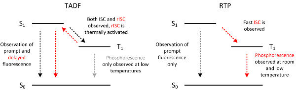
Figure 1: Scheme showing the differences between triplet-harvesting molecules: delayed fluorescent (TADF) and phosphorescent (RTP). The protocol presented here (if extended by temperature-dependent measurements) can be used to investigate these molecules and record their key properties. Note: in some RTP molecules, the prompt fluorescence may not be observed. Please click here to view a larger version of this figure.
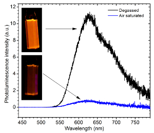
Figure 2: Photoluminescence spectra showing an increase of photoluminescence intensity after degassing a solution. The figure shows the effect of degassing a toluene solution of a platinum-based phosphorescent metalocomplex using the protocol presented in this work. Please click here to view a larger version of this figure.
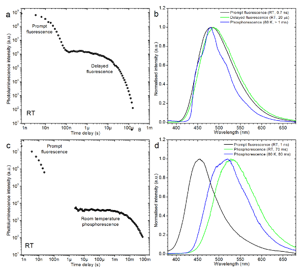
Figure 3: Representative results. (a) This panel shows the luminescence decay transient of a TADF emitter in toluene. (b) This panel shows the representative spectra recorded in the same experiment as is shown in panel a, with the phosphorescence spectrum recorded at 80 K. (c) This panel shows the luminescence decay transient of an RTP molecule in cyclo olefin polymer. (d) This panel shows spectra recorded in the same experiment as is shown in panel c, along with a low-temperature phosphorescence spectrum. Please click here to view a larger version of this figure.
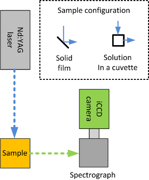
Figure 4: Schematic of the measurement system. The Nd:YAG laser produced third harmonics at 355 nm. The laser light hit the sample, which absorbed part of the light and emitted photoluminescence shortly after. The photoluminescence was then collimated and focused onto a spectrograph where it was refracted. The light was then recorded by the iCCD camera, which enabled recording the spectra in the time domain. Note the configuration of the solid and liquid samples. Please click here to view a larger version of this figure.
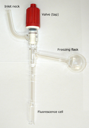
Figure 5: Photograph of a degassing cuvette used in room-temperature measurements. The cuvette consists of quartz fluorescence cell, a glass freezing flask, and a valve. All elements are connected with glass tubes. Note that the cuvette is not a commercially available item. Please click here to view a larger version of this figure.
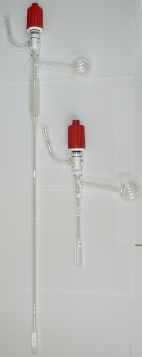
Figure 6: Comparison of a regular degassing cuvette and a cuvette used for low-temperature experiments. The cuvette for low-temperature measurements is very similar to the regular one. However, it is fitted with a long glass tube to fit the dimensions of the liquid nitrogen cryostat, and the quartz fluorescence cell is made of one piece of quartz; therefore, it is resistant to temperature changes in a wide range of temperatures. Please click here to view a larger version of this figure.
Discussion
Loading...
$$\rightleftharpoonup{xx}$$
$$\longleftharp{xx}$$,
$$\longrightharp{xx}$$,
Degassing a solution is one of the most critical points in this method. Plastic inlet valves become worn easily and the system stops being hermetic. If in doubt, it is advised to check the cuvette with a known material with an established degassing factor. The cuvettes are also fragile; therefore, degassing should be performed with caution.
As the system typically requires a pulsed Nd:YAG laser, a proper maintenance of the laser unit must be performed regularly. The pumping flashlamp should be replaced regularly, and this should only be done by a qualified technician or another experienced person.
As the laser requires 30 min to warming up, it is a good practice to turn on the laser before degassing the sample. Once the sample is degassed, the laser should be ready for taking the measurements. However, the degassing time for a film is difficult to determine using this equipment. Therefore, it is worth to perform a steady-state experiment with a conventional fluorometer to estimate the degassing time (a stabilization of the photoluminescence intensity upon pumping down).
For short-lived emitters (i.e., those whose fluorescence decays within a few nanoseconds), there will be only a few spectra recorded, as the emission decay lasts for a short period of time. In this case, TCSPC or a streak camera would perform much better. On the other hand, long-lived emitters can be problematic if the emission lasts for more than 100 ms (i.e., phosphorescence). To expand the effective time window, a nitrogen laser is used in these cases. This allows reducing the repetition rate of the laser to 1 Hz and extending the time window to 1 s.
The protocol shown here is only exemplary and is dedicated to a new and inexperienced user. An experienced operator can modify the protocol in various different ways. There is a potential to further develop the system to extend the camera's sensitivity in red and (NIR) by replacing the photocathode, as mentioned in the Introduction.
The data analysis in the case of this experiment is a time-consuming job, as each experiment gives ca. 100 spectra. The spectra have to be divided by the integration time to reconstruct the luminescence decay, and often also normalized (divided by the maximum, standardized, or area-normalized) in order to facilitate an analysis of the spectra at different delay times. During the analysis, differences in the spectra (i.e., gradual red or blue shifts) are being looked for. If the measurement is performed in function of the temperature, then the spectra can show the presence of delayed fluorescence or phosphorescence, or both, depending on the temperature or time delay used. Transient decays are obtained by plotting the integrated luminescence spectra against the time delay, after dividing each spectrum by their respective integration time. The photoluminescence transient decay is obtained and can be fitted in order to calculate the radiative lifetime of the prompt and the delayed fluorescence or phosphorescence.
Disclosures
Loading...
$$\rightleftharpoonup{xx}$$
$$\longleftharp{xx}$$,
$$\longrightharp{xx}$$,
The authors have nothing to disclose.
Acknowledgements
Loading...
$$\rightleftharpoonup{xx}$$
$$\longleftharp{xx}$$,
$$\longrightharp{xx}$$,
The research leading to these results has received funding from the European Union's Horizon 2020 research and the innovation program under the Marie Skłodowska-Curie grant agreement No. 674990 (EXCILIGHT), and from EPSRC, EP/L02621X/1.
Materials
| Name | Company | Catalog Number | Comments |
|---|---|---|---|
| Degassing cuvette | Not commercial product | ||
| Nd:YAG laser | EKSPLA | EKSPLA NL204-0.5K-TH | |
| Gated iCCD camera | Stanford Computer Optics | 4Quick Edig | |
| Spectrograph | Horiba Instruments inc. | TRIAX180 | |
| Liquid nitrogen cryostat | Janis Research | ||
| Helium closed cycle cryostat | Cryomech | ||
| Fluorolog fluorometer | Jobin Yvon | ||
| Liquid nitrogen | Technical | ||
| Cyclo olefin polymer | Zeon | Zeonex 480 | |
| Toluene | ROMIL | H771 | Toluene SpS |
References
Loading...
$$\rightleftharpoonup{xx}$$
$$\longleftharp{xx}$$,
$$\longrightharp{xx}$$,
- Uoyama, H., Goushi, K., Shizu, K., Nomura, H., Adachi, C. Highly efficient organic light-emitting diodes from delayed fluorescence. Nature. 492 (7428), 234-238 (2012).
- Dias, F. B., Penfold, T. J., Monkman, A. P. Photophysics of thermally activated delayed fluorescence molecules. Methods and Application in Fluorescence. 5, 012001(2017).
- Dias, F. B., et al. Triplet Harvesting with 100% Efficiency by Way of Thermally Activated Delayed Fluorescence in Charge Transfer OLED Emitters. Advanced Materials. 25, 3707-3714 (2013).
- Endo, A., et al. Efficient up-conversion of triplet excitons into a singlet state and its application for organic light emitting diodes. Applied Physics Letters. 98, 083302(2011).
- Kaji, H., et al. Purely organic electroluminescent material realizing 100% conversion from electricity to light. Nature Communications. 6, 1-8 (2015).
- Data, P., et al. Dibenzo[a,j]phenazine-Cored Donor-Acceptor-Donor Compounds as Green-to-Red/NIR Thermally Activated Delayed Fluorescence Organic Light Emitters. Angewandte Chemie International Edition. 55 (19), 5739-5744 (2016).
- Santos, P. L., et al. Engineering the singlet-triplet energy splitting in a TADF molecule. Journal of Materials Chemistry C. 4 (17), 3815-3824 (2016).
- Jankus, V., et al. Highly Efficient TADF OLEDs: How the Emitter-Host Interaction Controls Both the Excited State Species and Electrical Properties of the Devices to Achieve Near 100% Triplet Harvesting and High Efficiency. Advanced Functional Materials. 24 (39), 6178-6186 (2014).
- Al Attar, H. A., Monkman, A. P. Dopant Effect on the Charge Injection, Transport, and Device Efficiency of an Electrophosphorescent Polymeric Light-Emitting Device. Advanced Functional Materials. 16 (17), 2231-2242 (2006).
- Jankus, V., et al. The role of exciplex states in phosphorescent OLEDs with poly(vinylcarbazole) (PVK) host. Organic Electronics. 20, 97-102 (2015).
- Kozhevnikov, V. N., et al. Cyclometalated Ir(III) Complexes for High-Efficiency Solution-Processable Blue PhOLEDs. Chemistry of Materials. 25 (11), 2352-2358 (2013).
- Jankus, V., Chiang, C., Dias, F., Monkman, A. P. Deep Blue Exciplex Organic Light-Emitting Diodes with Enhanced Efficiency; P-type or E-type Triplet Conversion to Singlet Excitons. Advanced Materials. 25, 1455-1459 (2013).
- Li, J., Zhang, Q., Nomura, H., Miyazaki, H., Adachi, C. Thermally activated delayed fluorescence from 3n* to 1n* up-conversion and its application to organic light-emitting diodes. Applied Physics Letters. 105, 013301(2014).
- Endo, A., et al. Thermally Activated Delayed Fluorescence from Sn4+ β-Porphyrin Complexes and Their Application to Organic Light-Emitting Diodes - A Novel Mechanism for Electroluminescence. Advanced Materials. 21 (47), 4802-4806 (2009).
- Nakanotani, H., et al. High-efficiency organic light-emitting diodes with fluorescent emitters. Nature Communications. 5, 4016(2014).
- Graves, D., Jankus, V., Dias, F. B., Monkman, A. Photophysical Investigation of the Thermally Activated Delayed Emission from Films of m-MTDATA:PBD Exciplex. Advanced Functional Materials. 24 (16), 2343-2351 (2014).
- Ward, J. S., et al. The interplay of thermally activated delayed fluorescence (TADF) and room temperature organic phosphorescence in sterically-constrained donor-acceptor charge-transfer molecules. Chemical Communications. 52, 3-6 (2016).
- Data, P., et al. Exciplex Enhancement as a Tool to Increase OLED Device Efficiency. The Journal of Physical Chemistry C. 120 (4), 2070-2078 (2016).
- Okazaki, M., et al. Thermally Activated Delayed Fluorescent Phenothiazine-Dibenzo[a,j]phenazine-Phenothiazine Triads Exhibiting Tricolor-Changing Mechanochromic Luminescence. Chemical Science. (4), (2017).
- Dos Santos, P. L., Dias, F. B., Monkman, A. P. Investigation of the Mechanisms Giving Rise to TADF in Exciplex States. The Journal of Physical Chemistry C. 120 (32), 18259-18267 (2016).
- Costa, B. B. A., et al. Indirect consequences of exciplex states on the phosphorescence lifetime of phenazine-based 1,2,3-triazole luminescent probes. Physical Chemistry, Chemical Physics. 19, 3473-3479 (2017).
- Dos Santos, P. L., Ward, J. S., Bryce, M. R., Monkman, A. P. Using Guest-Host Interactions to Optimize the Efficiency of TADF OLEDs. The Journal of Physical Chemistry Letters. 7 (17), 3341-3346 (2016).
- Pander, P., Swist, A., Soloducho, J., Dias, F. B. Room temperature phosphorescence lifetime and spectrum tuning of substituted thianthrenes. Dyes and Pigments. 142, 315-322 (2017).
- Dias, F. B., et al. The Role of Local Triplet Excited States and D-A Relative Orientation in Thermally Activated Delayed Fluorescence: Photophysics and Devices. Advanced Science. , 80(2016).
- Etherington, M. K., et al. Regio- and conformational isomerization critical to design of efficient thermally-activated delayed fluorescence emitters. Nature Communications. 8, 1-11 (2017).
- Etherington, M. K., Gibson, J., Higginbotham, H. F., Penfold, T. J., Monkman, A. P. Revealing the spin-vibronic coupling mechanism of thermally activated delayed fluorescence. Nature Communications. 7, 13680(2016).
- ICCD System Overview. , Available from: http://standordcomputeroptics.com/technology/iccd-system-overview.html (2017).
- Pander, P., et al. Synthesis and characterization of chalcogenophene-based monomers with pyridine acceptor unit. Electrochimica Acta. 210, 773-782 (2016).
- Data, P., et al. Electrochemically Induced Synthesis of Triphenylamine-based Polyhydrazones. Electrochimica Acta. 230, 10-21 (2017).
- Zhang, Q., et al. Design of efficient thermally activated delayed fluorescence materials for pure blue organic light emitting diodes. Journal of the American Chemical Society. 134, 14706-14709 (2012).
- Mehes, G., Nomura, H., Zhang, Q., Nakagawa, T., Adachi, C. Enhanced electroluminescence efficiency in a spiro-acridine derivative through thermally activated delayed fluorescence. Angewandte Chemie International Edition. 51 (45), 11311-11315 (2012).
Reprints and Permissions
Request permission to reuse the text or figures of this JoVE article
Request Permission