An additive manufacturing strategy for processing UV-crosslinkable hydrogels has been developed. This strategy allows for the layer-by-layer assembly of microfabricated hydrogel structures as well as the assembly of independent components, yielding integrated devices containing moving components that are responsive to magnetic actuation.
Method Article
An Additive Manufacturing Technique for the Facile and Rapid Fabrication of Hydrogel-based Micromachines with Magnetically Responsive Components
In This Article
Summary
Abstract
Polyethylene glycol (PEG)-based hydrogels are biocompatible hydrogels that have been approved for use in humans by the FDA. Typical PEG-based hydrogels have simple monolithic architectures and often function as scaffolding materials for tissue engineering applications. More sophisticated structures typically take a long time to fabricate and do not contain moving components. This protocol describes a photolithography method that allows for facile and rapid microfabrication of PEG structures and devices. This strategy involves an in-house developed fabrication stage that allows for the rapid fabrication of 3D structures by building upwards in a layer-by-layer fashion. Independent moving components can also be aligned and assembled onto support structures to form integrated devices. These independent components are doped with superparamagnetic iron oxide nanoparticles that are sensitive to magnetic actuation. In this manner, the fabricated devices can be actuated using external magnets to yield movement of the components within. Hence, this technique allows for the fabrication of sophisticated MEMS-like devices (micromachines) that are composed entirely out of a biocompatible hydrogel, able to function without an onboard power source, and respond to a contact-less method of actuation. This manuscript describes the fabrication of both the fabrication set-up as well as the step-by-step method for the microfabrication of these hydrogels-based MEMS-like devices.
Introduction
MEMS devices have found a multitude of applications especially in the field of medical devices. Although they lend a lot of added functionalities and the miniaturized nature of these devices make them attractive for use as implantables1,2,3, these devices often have inherent safety and biocompatibility issues, as they are composed of materials that could be harmful to the human body (e.g., metals, batteries, etc.)4,5,6. PEG-based hydrogels are liquid swollen polymer networks and have been frequently used for applications such as tissue engineering scaffolds largely in part due to their high biocompatibility7,8. PEG-based hydrogels have also been FDA-approved for use in humans9,10,11. However, due to the material properties of hydrogel, they do not easily withstand normal manufacturing processes such as techniques used in typical silicon-based microfabrication. Thus, hydrogel-based constructs are typically limited to simple monolithic architectures. Current efforts at microfabrication of hydrogels have resulted in structures with micron-sized features; however, these structures are often of a single layer and a single material12,13 and lack moving components14,15,16.
In a previous work, we describe a strategy for fabricating micromachines that are composed entirely of a biocompatible PEG-based hydrogel material17. Micron-sized features can be fabricated easily using a photolithography method and these structures can be built upwards using a layer-by-layer method, enabled by the precise z-axis movement of the substrate on which the hydrogels are polymerized. Hydrogels of different compositions can be fabricated adjacent to each other. Additionally, these devices have moving components that can be actuated using an external magnet. This versatile technique is also suitable for processing any soft material or hydrogel that is photo-polymerizable. Thus, this technique is well-suited for fabricating sophisticated MEMS-like devices composed entirely of hydrogels.
Protocol
1. Fabrication Stage
- Assemble the fabrication (Figure 1) set-up consisting of an in-house built stage and PDMS chamber in which the hydrogel components are polymerized. The fabrication stage consists of an acrylic top, in which tracks and channels were machined to allow for vacuum connections, a holder for the fixture of a micrometer head within the vacuum-enabled stage, and threaded steel posts that allow the entire stage to be fixed onto steel base for stabilization.
- Fix the head of the micrometer with an acrylic piece that is machined to have tracks for vacuum connection. Vacuum connections allow the user to hold down the PDMS chamber as well as move the flexible membrane within the PDMS chamber.
- Position a UV light source (320 - 500 nm) above the fabrication stage such that the incident angle of the light is perpendicular to the horizontal plane of the stage (Supplementary Figure 1).
2. Fabrication of PDMS Chamber and Determining its "Zero" Level
- Make a PDMS chamber in which the hydrogels will be polymerized (See Figure 1A, PDMS chamber). This chamber consists of a PDMS well with a flexible membrane onto which a glass coverslip is bonded. The glass coverslip that is bonded to the flexible PDMS membrane is further treated to prevent adhesion of hydrogels (step 2.1.7).
- Prepare a 9 part PDMS base to 1 part curing agent mixture (by weight).
- Stir well with a glass rod to ensure that the base and curing agents are well mixed. Centrifuge at 1,000 x g to remove air bubbles.
- Carefully pour the PDMS mixture into two glass Petri dishes to yield a thick layer (~3 mm) and a thin layer (~0.2 mm). Place PDMS-filled Petri dishes on a flat, level surface and cure overnight at room temperature or for 30 minutes in an oven with temperature set at a minimum of 75 °C.
NOTE: A thin layer of PDMS is required for the base of the PDMS chamber as it ensures the generation of a flexible layer that can be easily moved in the z-direction by the micrometer screw gauge. The PDMS layers have to be flat and level to ensure that the polymerized hydrogel layers are of uniform thickness. - After the PDMS is fully cured, cut a 4 cm diameter circle into the thick layer using a scalpel blade or penknife. Peel the thick PDMS layer off from the glass Petri dish. Place the thick PDMS layer (bottom-side up) and the thin PDMS layer (still in the glass Petri dish) into a plasma oven.
- Plasma treat the two PDMS layers (30 s, air plasma) and bond the bottom side of the thick PDMS layer to the top-side of the thin PDMS layer. Remove the bonded pieces from the glass Petri dish to form a circular well with the thin layer forming a flexible membrane base.
NOTE: Prior to removal of the bonded layers from the glass Petri dish, the two bonded layers can be placed on a hot plate at 95 °C to encourage bonding of the layers. - Plasma bond a glass coverslip (no. 2, 22 mm x 22 mm) to the top-side of the flexible PDMS membrane; plasma treat both the glass coverslip and PDMS chamber from step 4 for 30 s (air plasma) and place the glass coverslip in contact with the top-side of the flexible membrane base to bond it to the membrane.
- Vapor silanize the PDMS chamber with trichloro (1H, 1H, 2H, 2H -perfluorooctyl) silane (PFOTS) for at least 30 minutes; place the PDMS chamber in a vacuum desiccator along with a small Petri dish with 60 µL of PFOTS and connect the sealed desiccator to the central laboratory vacuum system. Leave the desiccator connected to the vacuum system for at least 30 minutes.
- Ensure that the vacuum seal of the desiccator is generated and that the droplet of PFOTS "bubbles" after 5 - 10 minutes. Vapor silanization of the PDMS chamber allows facile removal of formed hydrogel layers and prevents strong adhesion of polymerized PEG hydrogels to the glass surface after prolonged use.
- To determine the "zero" level of the PDMS chamber, place it on a vacuum-enabled stage (connected to laboratory central vacuum system).
- Apply negative pressure to hold the PDMS chamber down. The PEG hydrogel structures will be polymerized within this PDMS chamber (Figure 1A, Fabrication area).
- Place an untreated glass coverslip on top of the PDMS chamber such that it covers the well. The distance between the top glass coverslip (top substrate) and the bottom glass coverslip (bottom substrate) defines the thickness of the hydrogel layer that is formed within the PDMS chamber.
- Using the micrometer head, push the bottom substrate upwards until it is in contact with the top substrate. Use the reading on the micrometer head as the "zero" level of the PDMS chamber and as a reference when defining the thickness of the polymerized hydrogel layers.
3. Photomask Design for Photopolymerization of Hydrogel Microstructures
- To design the photomasks, use CAD software.
- Design each unique layer of the hydrogel structure that is to be fabricated. Refer to Figure 2 for the example device fabricated using this protocol. Figure 2 shows 3D schematic of this device, the corresponding layers to be fabricated as well as the photomasks that were designed for the fabrication of these individual layers.
- Design photomasks in dark field; features to be polymerized should be transparent and the background is opaque (Figure 2C, Supplementary Figure 2).
- Incorporate alignment marks into the photomask designs to facilitate alignment of the photomasks during the fabrication process.
- Print the designs as transparency photomasks at the highest resolution available and at high pixel densities.
4. Treatment of Glass Coverslips to Prevent Adhesion of Hydrogels
- To create surfaces that repel the polymerized PEG hydrogels, glass coverslips are coated with a thin layer of PDMS.
- Prepare PDMS (9:1 base to curing agent ratio) and centrifuge at 1,000 x g to remove air bubbles.
- Apply a thin coat of PDMS to cleaned glass coverslips and leave to cure on a flat, level surface within an oven (>75 °C, 30 min).
5. Layer-by-layer Fabrication of Hydrogels: Top Sealing Layer and Bottom Support Structures
- To create a hydrogel layer that will subsequently be used to seal the formed device, use an untreated piece of glass coverslip (No.2) as a "lid" for the PDMS chamber. This "lid" is referred to as the top substrate.
- Starting from the "zero" level of the device, lower the bottom substrate using the micrometer head to the desired height. The distance between the top and bottom substrates defines the thickness of the first hydrogel layer (Z1, Figure 3A).
- Deposit a small volume of the PEGDA prepolymer (e.g., a mixture of 400Da PEGDA with 1% Darocur 1173), sufficient to cover the bottom substrate.
- Place the top substrate onto the PDMS chamber.
NOTE: It is important to ensure that there are no air bubbles trapped between the top and bottom substrates. - Place a photomask with desired design on top of the top substrate (Figure 2C (i)). Ensure that the mask is in full contact with the top substrate and aligned to the bottom substrate.
- Expose the hydrogel prepolymer to UV light through the photomask (Step 1, Figure 3A). Ensure that exposure is done within an enclosed space that prevents stray UV light exposure to the surrounding area.
Caution: Wear UV protection (e.g., UV goggles) when operating the system.
NOTE: The power and duration of exposure depends on the type of UV system and PEGDA prepolymer used. - For example, for a 200 W UV lamp and 99% PEGDA (400 Da PEGDA with 1% photoinitiator (v/v)) prepolymer solution, set the lamp power at 16% (corresponding to ~2.3 W/cm2) and fully cure the hydrogels within 4 seconds. The duration of exposure should be increased with decreasing lamp power and increasing PEG chain length of the prepolymer used.
- After the hydrogel layer has been polymerized, lift the top substrate off the PDMS chamber. The polymerized layer should be adhered onto the top substrate (inset for Step 1, Figure 3A). Reserve this adhered layer for use later to seal the assembled device. Shield this polymerized layer from light.
NOTE: Keep this polymerized layer away from light and wet with excess uncrosslinked prepolymer to prevent the layer from drying out and cracking.
- To create the bottom support structures, use PDMS-coated glass coverslips as the top substrate of the PDMS chamber.
- Deposit more hydrogel prepolymer onto the bottom substrate and cover the PDMS well with a PDMS-coated glass coverslip. This is to ensure that the polymerized layers remain on the bottom substrate, allowing the user to build layers upwards (Step 2, Figure 3A).
- Repeat steps 5.1.4 and 5.1.5 with the desired photomask design (Figure 2c (iii)).
- Remove the top substrate and add more PEGDA prepolymer and lower the bottom substrate using the micrometer head to the desired level. This level should correspond to the thickness of the 2nd layer of hydrogel to be polymerized (Z2, Step 3, Figure 3A).
- Cover the PDMS well with the top substrate (PDMS-coated glass) and repeat steps 5.1.4 and 5.1.5.
- Continually build up layers of hydrogel as desired using steps 5.2.1 and 5.2.2 until the desired support structures are formed.
6. Assembling and Sealing the Hydrogel-based Device
- To assemble and seal the device, first remove the top substrate (PDMS-coated glass) and using a pair of tweezers, place pre-formed hydrogel components (e.g., gears, iron-doped components) onto the support structures (Part (i), Step 4, Figure 3A).
NOTE: A permanent magnet may be used to align any iron-doped components (refer to iron oxide doping of hydrogel components for fabrication steps). - To seal the device, first bring the bottom substrate to the final desired height of the assembled device using the micrometer screw gauge. This should be the final height of the device, taking into account the thickness of the layers, interior components and any clearances given for moving components (Z4, Step 5, Figure 3A)
- Place the pre-formed hydrogel layer adhered onto the untreated glass coverslip from 5.1 onto the partially assembled device (Part (ii), Step 4, Figure 3A). Carefully place the pre-formed layer such that it is correctly aligned to the structures below it.
- Place a photomask that allows for the sealing of the device but protects the interior moving components from UV exposure. Ensure that the moving components are not polymerized to the edges of the device, preventing their movement during actuation.
- Expose the entire structure to UV light (Part (i), Step 5, Figure 3A).
- Lift the glass coverslip from the fabrication stage. The sealed device should adhere to the top substrate ((Part (ii), Step 5, Figure 3A).
NOTE: If the device remains adhered to the bottom substrate, carefully lift the device with a pair of flat-tipped (non-serrated) tweezers or a flat spatula. - Carefully remove excess unpolymerized PEGDA using vacuum suction and carefully lift the device off the glass coverslip using a pair of flat tweezers or flat spatula.
- Place the device into saline solution or DI water. Hydrogels swell in solution. Leave the device in solution for at least 30 minutes to allow for stabilization and expansion of the device and the interior components.
NOTE: If the device is to be used for in vivo implantation, it is important to rinse and leach off any uncrosslinked prepolymers. This can be done by changing the solution in which the device is incubated in every hour (at least 3 rinses) and leaving the device in solution overnight, and rinsing off with more solution. - Remove air within the device by placing the device within a Petri dish filled with DI water or saline within a vacuum chamber (connected to central laboratory vacuum systems) for at least 30 minutes. This will result in degassing of the device and the device will be filled with solution once negative pressure is removed.
NOTE: Keep the device hydrated/in solution at all times. The device may crack should it be left to dry out.
7. Iron Oxide Doping of Hydrogel Components
- Prepare a PEGDA prepolymer solution with 1% photoinitiator (e.g., 99% (v/v) PEGDA (400 Da) with 1% Darocur 1173).
- Using this prepolymer solution, make a 5% (w/v) solution of iron-oxide (II, III) nanoparticle solution. Weigh out 5 mg of iron oxide nanoparticles and add 100 µL of PEGDA prepolymer. Pipette up and down and vortex to ensure uniform mixing.
- Ensure that nanoparticles are homogenously dispersed within the PEGDA prepolymer before each use as the nanoparticles will sediment over time.
- Pipette a small volume of the iron oxide - PEGDA prepolymer mixture onto the bottom substrate of the PDMS chamber.
- Cover the PDMS well with the top substrate (PDMS-coated glass) to ensure that the formed hydrogels remain on the bottom substrate.
- Bring the bottom substrate to the desired height using the micrometer head.
NOTE: Thin layers (200 µm) of iron oxide-doped PEGDA should be polymerized with each single exposure. This is due to the decrease in depth of penetration of the UV light as the iron oxide nanoparticles are opaque and are able to absorb and block UV light. - Using a photomask that defines the shape of the segment to be doped with iron oxide within the moving component, expose the thin layer of iron oxide doped prepolymer to UV light (Figure 4(i)).
NOTE: UV exposure time should be increased to ensure that the iron-doped segment is fully cross-linked (~10 seconds). - Lower the bottom substrate and repeat step 6, building the iron-doped segment in thin layers each time to the desired height (Figure 4(ii)). A total of 5 layers should be polymerized to yield a 1mm tall iron-doped segment.
- After the iron-doped segment is complete (Figure 4(iii)), remove any excess iron-doped prepolymer using vacuum suction. Do not remove the iron-doped segment from the fabrication stage.
- Deposit the PEGDA prepolymer (undoped) onto the polymerized iron-doped segment. Bring the bottom substrate to the final height of the component to be completed. Cover the PDMS well with the top substrate (PDMS-coated glass).
- Using a photomask that defines the entire shape of the moving component, expose the PEGDA prepolymer, as well as the iron-doped segment, to UV light (Figure 4(iv)).
- Remove the top substrate and remove excess unpolymerized PEGDA prepolymer using vacuum suction. A PEG component with a doped iron-oxide segment should remain on the bottom substrate. Gently lift this component using a pair of tweezers.
- Reserve this iron-doped component for assembly onto support structures of a PEG-based device (Part (i), Step 4, Figure 3A). Shield this component from light and ensure that it remains wetted with uncrosslinked prepolymer before use.
8. Actuation of the Assembled Device
NOTE: The iron-doped components within the assembled device can be actuated to move using a strong permanent magnet such as neodymium (N52 strength). Be careful to avoid pinching hazards as these magnets are very strongly attracted to ferromagnetic materials.
- Place a neodymium magnet below or above the device within 1 - 2 cm away from the device. While moving the magnet, the movement of the iron-oxide doped components should shadow the movement of the magnet.
NOTE: An actuator can be built using a motor that is attached with a magnet. The rotation of the motor should allow for rotational actuation of the iron doped component.
Results
Figure 3B shows images of the layers of hydrogels polymerized using the fabrication set-up. Figure 3B(i) shows a fabricated 400 µm thick base layer with a 600 µm aperture. Figure 3B(ii) shows a further two layers that were layered on top of the base layer; a 500 µm tall perimeter and an 800 µm tall axle in the middle. The total fabrication time for these three layers was less than 3 minutes taking into account 4 seconds of exposure for each layer and time taken to adjust the height of the bottom substrate and alignment of photomasks. Previous work performed on the same fabrication set-up demonstrates that a variety of designs can be fabricated with resolutions as high as 100 µm.
The hydrogel components could also be easily doped with iron oxide nanoparticles. The exposure times were optimized to ensure thin layers (200 µm) of PEGDA prepolymers doped with iron oxide nanoparticles could be fully polymerized. Figure 5A shows the photomask used to define the shape of the iron oxide segment to be polymerized. The un-doped PEGDA prepolymer can be fully polymerized within 4 seconds of UV exposure. However, when the iron oxide doped prepolymer was exposed for 4 seconds to UV, the resultant hydrogel was not fully polymerized, as can be seen in Figure 5C. The segment generated was thinner (as compared to a fully cross-linked segment shown in Figure 5B), and the edges were uneven with compromised fidelity as compared to the shape defined by the photomask. UV exposure of 10 seconds was required to fully cross link the iron oxide segment and Figure 5B shows the iron oxide segment that was generated; the polymerized iron oxide segment is of full thickness (200 µm) with straight edges, and shape fidelity is closely maintained as compared to the photomask (Figure 5A). Conversely, over exposure (>15 seconds) to UV light generated iron oxide segments that were over polymerized. Figure 5D shows an over polymerized segment that has poor shape fidelity and is larger than the shape defined by the photomask.
Figure 6A shows a complete device after sealing with proper alignment by utilizing photomasks with alignment marks. The gear within the device is entirely within the central void of the device and is thus responsive to magnetic actuation. Figure 6B shows a device with a misaligned sealing layer. Figure 6C shows the bottom layers of hydrogel and the gear itself elucidated with black outlines and Figure 6D shows the misaligned sealing of the top hydrogel layer elucidated in white outlines. As can be seen from Figure 6D, portions of the gear that fall within regions where polymerization would take place during sealing (shown in red fill) results in portions of the gear being anchored to the bulk of the hydrogel material. This prevents the gear from moving during actuation.
Figure 7 shows a functional single gear device that was fabricated (total fabrication time ~15 minutes). The total thickness of the device is 2 mm and the longest dimension of the device is 13 mm. The top and bottom layers of the device is 400 µm thick and the gear has a height of 1 mm. This design allows for a 100 µm clearance on the top and bottom surface of the gear to allow for movement. The top most layer of the device has a 600 µm aperture and the axle for the gear is 400 µm in diameter. Figure 5B shows images of the device when it is actuated with a magnet such that the gear performs a full rotation as can be observed from the change in position of the iron oxide segment from (i) through (vi).
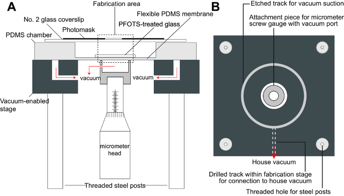
Figure 1. Fabrication set-up for hydrogel-based micromachines. A) Schematic of fabrication stage. This schematic shows the various components of the fabrication set-up including the PDMS chamber in which the hydrogels are formed within the fabrication area, a vacuum-enabled stage which holds down the PDMS chamber as well as attaches the flexible membrane to a micrometer head for height control, and top substrate consisting of a glass coverslip that is either untreated or coated with PDMS. B) Schematic of the top view of the fabrication stage (without PDMS chamber). The UV light source is then positioned such that the incident angle of the light is perpendicular to the horizontal plane of the fabrication stage (not shown in figure). Please click here to view a larger version of this figure.
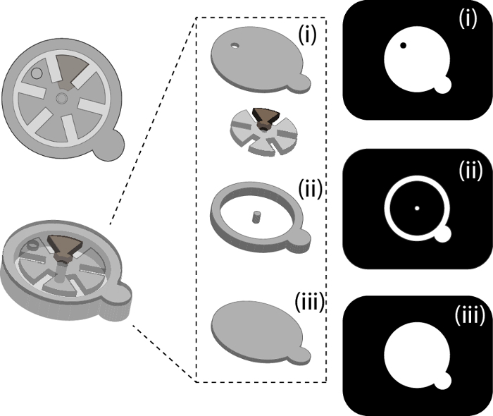
Figure 2. Schematic of single-gear hydrogel-based device and photomasks used for each layer. A) Schematic of the top- and oblique-view of a typical hydrogel-based device that can be fabricated using this strategy. This device consists of a single gear that contains an iron-doped segment which allows for magnetic control. B) Schematic of the individual layers and components within the device. This single-gear device consists of a top sealing layer (i), support structures such as the post for the iron-doped gear and the walls of the device (ii) as well as a bottom layer (iii). C) Photomask designs used to fabricate the single-gear device. The photomasks are designed dark field; desired features are left transparent while the background is dark. This panel shows the photomask designs corresponding to the top sealing layer (i), support structures (ii) and bottom layer (iii). Please click here to view a larger version of this figure.
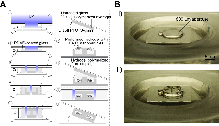
Figure 3. Layer-by-layer photolithography of hydrogel-based micromachines. A) Schematic of step-by-step process for device fabrication within the fabrication area of the PDMS chamber. 1: A small volume of PEGDA prepolymer is pipetted onto the glass coverslip bonded to the flexible membrane of the PDMS chamber (bottom substrate). A piece of untreated glass coverslip is used as the top substrate and a photomask is placed on top of this top substrate. The height of the bottom substrate is brought to the desired height (Z1) using the micrometer head. The hydrogel prepolymer is then exposed to UV light through the photomask. The top substrate can then be lifted off the PDMS chamber and the hydrogel remains adhered to the top substrate (inset). This layer is then reserved for later use. 2: Step 1 is repeated but the top substrate is now replaced with PDMS-coated glass. The polymerized hydrogel will remain adhered to the bottom substrate. 3: The height of the bottom substrate is lowered (Z2> Z1) and more prepolymer can be added to the fabrication area. A second photomask is used and the prepolymer is exposed to UV light once again. 4: Step 3 can be repeated (Z3 >Z2) until the desired support structures are created. (i) Once the support structures are completed, the top substrate can be removed to allow for access to fabrication area for introduction of any preformed hydrogel components (e.g., iron-doped gear). (ii) Once the preformed components have been placed and properly aligned, the hydrogel layer from Step 1 can be placed on top of the fabricated structure and aligned. 5: All the layers are then exposed to UV light through a photomask that seals the edges of the device. (i) The sealing step seals the entire device while the interior components are shielded from further UV exposure. (ii) The sealed device can then be lifted off the fabrication chamber as it would preferentially adhere to the top substrate. Please click here to view a larger version of this figure.
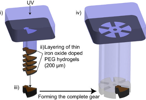
Figure 4. Steps for iron-oxide nanoparticle doping of hydrogel components. (i) UV light is exposed through a photomask defining the iron oxide-doped segment within the hydrogel gear. (ii) Thin (200 µm) layers of iron oxide-doped hydrogel is polymerized each time and stacked on top of each other. (iii) The layer of thin layers creates a segment with total height of 1 mm. This segment is left in the fabrication layer. (iv) Un-doped prepolymer is then deposited into the fabrication area and a photomask that defines the complete shape of the gear is then used during cross-linking. This enables the formation of the complete gear with an iron oxide-doped segment. Please click here to view a larger version of this figure.
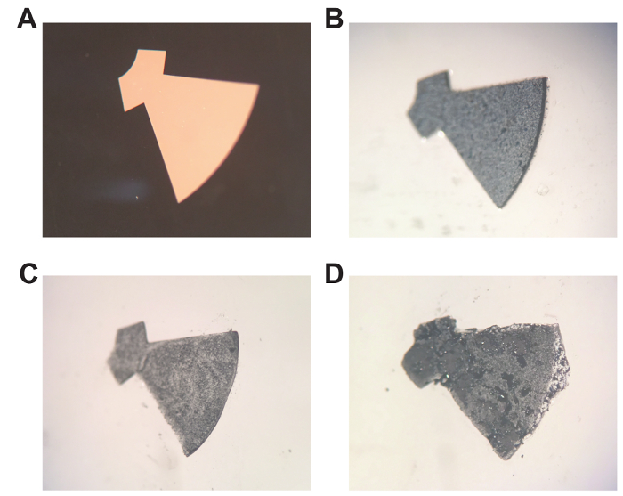
Figure 5. Photopolymerization of iron oxide-doped hydrogel components. A) Photomask of gear segment to be doped with iron oxide nanoparticles. B) Iron oxide-doped hydrogel that has been optimally polymerized (10 s exposure). C) Iron oxide-doped hydrogel that has been under-polymerized (4 s exposure). D) Iron oxide-doped hydrogel that has been over-polymerized (20 s exposure). Please click here to view a larger version of this figure.
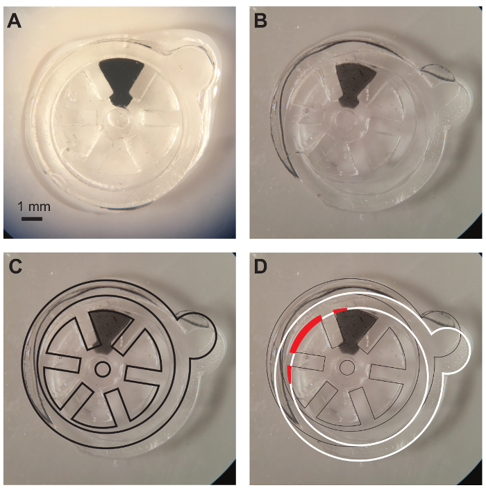
Figure 6. Alignment of hydrogel layers during sealing of device. A) Image showing the correct alignment of hydrogel layers with free-moving gear that is entirely within the void of the device. B) Image showing device with misaligned hydrogel layers (B, C, and D are images of the same device but with different layers highlighted). C) Same image as in (B) but with black outlines elucidating bottom layers which are correctly aligned. The gear is correctly placed within the bottom layers. D) Same image as in (B) but with white outlines showing the misaligned top layer of hydrogel. The gear has been partially polymerized during the sealing step and portions of the gear (red fill) has been anchored to the bulk material of the device. This renders the device non-functional. Please click here to view a larger version of this figure.
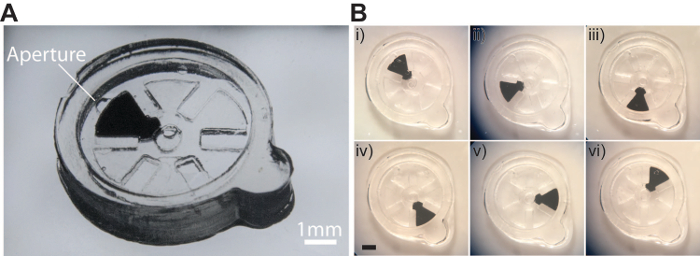
Figure 7. Actuation of a single-gear hydrogel-based micromachine. A) Image showing the fabricated device. B) Images showing the different orientations of the gear upon actuation. (i) From its initial orientation (0°), the gear is rotated by (ii) 60°, (iii) 120°, (iv) 180°, (v) 240°, and 300°. Scale bar is 1 mm Please click here to view a larger version of this figure.
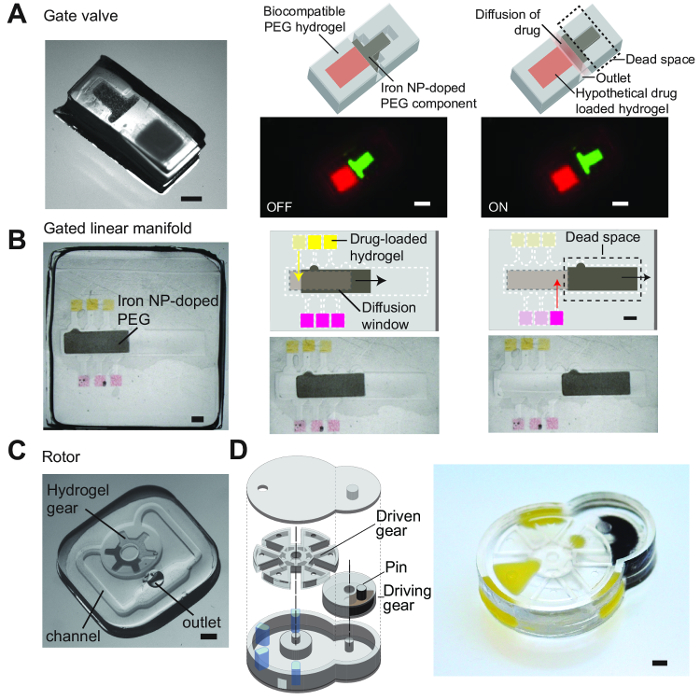
Figure 8. Versatile fabrication of various designs for hydrogel-based micromachines. A) A simple gate valve which controls the release of drugs from a single reservoir. The linear movement of the iron oxide-doped hydrogel component gates the diffusion of a hypothetical drug out through and outlet. B) A gated linear manifold which controls the release of drugs from multiple reservoirs. Each reservoir contains hypothetical drugs and the movement of the iron oxide-doped component gates the movement of drugs out of these reservoirs through a window of hydrogel that allows for the diffusion of these drugs out to the exterior. C) A simple rotor that can be actuated to spin about an axis. D) A sophisticated design based on the Geneva drive. A driving gear with a pin is able to engage a larger driven gear and produce intermittent movement; a full rotation of the driving gear rotates the driven gear by 60°. All scale bars are 1 mm. From Chin, S. Y. et al. Additive manufacturing of hydrogel-based materials for next-generation implantable medical devices. Science Robotics. 2 (2), (2017). Reprinted with permission from AAAS17. Please click here to view a larger version of this figure.
Discussion
This technique is a facile and rapid method for layer-by-layer photolithography of hydrogel microstructures. Using an additive manufacturing approach, we can easily build a variety of 3D structures out of biocompatible materials and even incorporate moving parts. This would thus enable the formation of entirely biocompatible microdevices. The technique is based on simple repetition of lithography steps, which is enabled by the precise control of the height of the bottom substrate via a micrometer head. Traditional fabrication techniques used in the MEMS industry, involving harsh processing techniques and sacrificial materials, is often not compatible with the processing of soft hydrogels. Other methods for 3D printing hydrogels, such as extrusion-based methods, are limited to spatial resolutions above 200 µm and print speeds of mm/s for simple structures that do not include moving parts18,19. Stereolithography (SLA) and digital light project (DLP) based bioprinters maybe be able to achieve better resolutions but are also a lot costlier to setup. These fabrication strategies are also not able to easily print overhangs without supporting substrate materials, which could be difficult to introduce and remove from the completed device. We circumvent this by aligning and polymerizing a pre-formed sealing layer to the fabricated support structure as a final step to form the completed device. The design of the fabrication set-up gives the user easy access to the fabricated structures and allows for the easy alignment of various components with the use of alignment marks.
The strategy presented here is also a lot faster than other techniques of similar resolutions; the total time taken for the demonstrated fabrication of the device with a rotating is about 15 minutes. Another added advantage of this fabrication strategy, though not demonstrated in this protocol but shown in our previous work17, is the ability for the user to quickly and easily change the type of polymer used between steps which can be done in small volumes. In this way, one can create devices that are a composite of different types of hydrogels. The device fabricated using this strategy also has the added advantage of contactless actuation as the gear contains a segment that is doped with iron oxide nanoparticles, rendering the gear sensitive to magnetic actuation and can thus be actuated using an external magnet. Additionally, the device is entirely biocompatible and hence may be safely implanted in vivo.
An important feature of this technique is the treatment of the different glass substrates, which enables the user to preferentially adhere or repel the polymerized hydrogel to either the bottom or top glass substrate. When a combination of untreated glass is used with a PFOTS-treated glass surface (bottom substrate), formed hydrogels will preferentially adhere to untreated glass, as they are repelled from the fluorinated surface of PFOTS-treated glass. Conversely, when PDMS-coated glass is used with the PFOTS-treated bottom substrate, hydrogels will tend to remain on the PFOTS-treated surface as PDMS surfaces more strongly repel the formed hydrogels. This feature allows one to build upwards, adhere hydrogels such that they are immobilized on glass substrates and can be reserved for alignment to other structures at a later point in time, or even build downwards. This adds to the flexibility of the technique and types of designs that can be fabricated as well as enables the incorporation and sealing in of independent, free-moving hydrogel components.
During the layer-by-layer fabrication, it is important to optimize the polymerization time used. Hydrogels should be optimally cross-linked such that they form at full thickness as well as at high fidelity as compared to the shapes defined by the photomask. This is dependent on the power of the lamp and the type of hydrogel used. Although not shown in this protocol, the polymerization time decreases with increasing lamp power and increases with increasing PEG chain length and decreasing concentrations of PEGDA used. Other factors that affect the amount of energy available for photopolymerization, such as the change in opacity of the prepolymer due to the addition of iron oxide nanoparticles (Figure 4), will also affect the polymerization time. Optimization for cross-linking conditions for different hydrogel compositions is thus required before the start of the fabrication process of devices.
The use of alignment marks on the photomasks and the proper alignment of the hydrogel layers, especially the final sealing layer, are important to ensure that proper sealing is performed, and the interior components are not inadvertently cross-linked to the surrounding support structures during the fabrication process. This would prevent these components from freely moving during magnetic actuation. As shown in Figure 5, a misaligned top sealing layer and photomask results in the crosslinking and anchoring of a portion of the gear to the bulk material of the device itself. As a result, this gear does not rotate when actuated with a magnet.
The devices can be actuated using strong permanent magnets such as neodymium magnets. These magnets generate strong magnetic forces when in close range to ferromagnetic materials and care should be taken to prevent injury. The device can be actuated to move without the magnet coming in contact with the device; the magnet can be held or placed ~1cm away from the device. The movement of the iron-doped components should mirror the movement of the magnet and can be actuated to move continuously or oriented intermittently as desired. The device can be manually actuated or an actuation set-up can be used. The magnet can be attached to any actuator (e.g., servo motor) to rotational movement. The speed of rotation of the magnet, and hence the speed of rotation of the iron-doped component, can be controlled using a microcontroller. This provides for a more precise method of actuation.
Figure 8 shows schematics and images of various designs from previous work that were fabricated using this same technique and demonstrate the versatility of this method. These designs range from simple devices that resemble valves (Figure 8A) to more complicated and sophisticated designs that draw inspiration from the Geneva drive design (Figure 8D) that comprise of 2 engaged gears that produce intermittent movement. The smallest features that can be generated using this technique were typically about 100 µm and each design is composed of multiple layers (3 to 6 layers). Different types of hydrogel compositions (with differing mechanical strengths and porosity) can also be polymerized and bonded to each other. Hence, one can easily combine the types of hydrogels to be used within a device depending on the required function of the different components within the device.
Disclosures
The authors have nothing to disclose
Acknowledgements
This work was supported by an NSF CAREER award, NIH R01 grant (HL095477-05), and NSF ECCS-1509748 grant. S.Y.C. was supported by the National Science Scholarship (PhD), which was awarded by the Agency for Science, Technology and Research (Singapore). We thank Keith Yeager for help with building the fabrication set-up, and Cyrus W. Beh for photographs of the set-up and devices.
Materials
| Name | Company | Catalog Number | Comments |
|---|---|---|---|
| Poly(ethylene glycol) (n) diacrylate [MW 400Da] | Polysciences, Inc | 01871-250 | PEGDA reagent for prepolymer |
| Darocur 1173 | Ciba Specialty Chemicals, Inc | - | Photoinitiator |
| Iron oxide (II, III) | Sigma Aldrich | 637106-25G | Iron oxide nanoparticles |
| Trichloro(1H,1H,2H,2H-perfluorooctyl)silane | Sigma Aldrich | 448931 | Fluorinated compound that is used to vapor silanize the PDMS chamber to prevent adhesion of hydrogel to the glass coverslip that is bonded to the flexible PDMS membrane with prolonged use of the PDMS chamber |
| Petri dish, glass | Sigma Aldrich | BR455743 | Glass petri dishes for casting PDMS layers for forming PDMS chamber |
| Sylgard 184 Silicone Elastomer Kit (PDMS) | Dow Corning | 240-4019862 | PDMS for fabrication chamber |
| Glass coverslips (No. 2), 50 x 45 mm | Fisher Scientific | FIS#12-543F | Glass substrates that cover the fabrication chamber |
| Fisherbrand Straight Flat Tip Forceps 4.75in | Fisher Scientific | FIS#16-100-112 | Tweezers for handling polymerized hydrogel layers/devices |
| Omnicure S2000 | Cadence Technologies Pte Ltd | 010-00148R | UV lamp |
| 5 mm Adjustable Collimating Adaptor | Cadence Technologies Pte Ltd | 810-00042 | Collimator for UV lightsource |
| Photomasks | CAD/Art Services Inc | - | Photomasks used to define hydrogel microstructures |
| Adobe Illustrator | Adobe | - | Designing of photomasks |
References
- Elman, N. M., Ho Duc, H. L., Cima, M. J. An implantable MEMS drug delivery device for rapid delivery in ambulatory emergency care. Biomedical Microdevices. 11 (3), 625-631 (2009).
- Gensler, H., Sheybani, R., Li, P. Y., Mann, R. L., Meng, E. An implantable MEMS micropump system for drug delivery in small animals. Biomedical Microdevices. 14 (3), 483-496 (2012).
- Grayson, A. C. R., et al. BioMEMS review: MEMS technology for physiologically integrated devices. Proceedings of the IEEE. 92 (1), 6-21 (2004).
- Frost, M., Meyerhoff, M. E. In vivo chemical sensors: tackling biocompatibility. Analytical Chemistry. 78 (21), 7370-7377 (2006).
- Voskerician, G., et al. Biocompatibility and biofouling of MEMS drug delivery devices. Biomaterials. 24 (11), 1959-1967 (2003).
- Ainslie, K. M., Desai, T. A. Microfabricated implants for applications in therapeutic delivery, tissue engineering, and biosensing. Lab Chip. 8 (11), 1864-1878 (2008).
- Burdick, J. A., Anseth, K. S. Photoencapsulation of osteoblasts in injectable RGD-modified PEG hydrogels for bone tissue engineering. Biomaterials. 23 (22), 4315-4323 (2002).
- Drury, J. L., Mooney, D. J. Hydrogels for tissue engineering: scaffold design variables and applications. Biomaterials. 24 (24), 4337-4351 (2003).
- Alcantar, N. A., Aydil, E. S., Israelachvili, J. N. Polyethylene glycol-coated biocompatible surfaces. Journal of Biomedical Materials Research Part A. 51 (3), 343-351 (2000).
- Cruise, G. M., et al. In vitro and in vivo performance of porcine islets encapsulated in interfacially photopolymerized poly(ethylene glycol) diacrylate membranes. Cell Transplantation. 8 (3), 293-306 (1999).
- Hoare, T. R., Kohane, D. S. Hydrogels in drug delivery: Progress and challenges. Polymer. 49 (8), 1993-2007 (2008).
- Ryu, W., Huang, Z., Prinz, F. B., Goodman, S. B., Fasching, R. Biodegradable micro-osmotic pump for long-term and controlled release of basic fibroblast growth factor. Journal of Controlled Release. 124 (1-2), 98-105 (2007).
- Lee, J. W., Park, J. H., Prausnitz, M. R. Dissolving microneedles for transdermal drug delivery. Biomaterials. 29 (13), 2113-2124 (2008).
- Hinton, T. J., et al. Three-dimensional printing of complex biological structures by freeform reversible embedding of suspended hydrogels. Science Advances. 1 (9), e1500758(2015).
- Tseng, H., et al. Fabrication and mechanical evaluation of anatomically-inspired quasilaminate hydrogel structures with layer-specific formulations. Annals of Biomedical Engineering. 41 (2), 398-407 (2013).
- Grogan, S. P., et al. Digital micromirror device projection printing system for meniscus tissue engineering. Acta Biomaterialia. 9 (7), 7218-7226 (2013).
- Chin, S. Y., et al. Additive manufacturing of hydrogel-based materials for next-generation implantable medical devices. Science Robotics. 2 (2), (2017).
- Diogo, G. S., Gaspar, V. M., Serra, I. R., Fradique, R., Correia, I. J. Manufacture of beta-TCP/alginate scaffolds through a Fab@home model for application in bone tissue engineering. Biofabrication. 6 (2), 025001(2014).
- Hockaday, L. A., et al. Rapid 3D printing of anatomically accurate and mechanically heterogeneous aortic valve hydrogel scaffolds. Biofabrication. 4 (3), 035005(2012).
Reprints and Permissions
