This work provides a method for the fabrication of droplet-based microfluidic platforms and the application of polyacrylamide microspheres for microsphere-PCR amplification. The microsphere-PCR method makes it possible to obtain single-stranded DNA amplicons without separating double-stranded DNA.
Method Article
A Droplet-Based Microfluidic Approach and Microsphere-PCR Amplification for Single-Stranded DNA Amplicons
* These authors contributed equally
Opens in a new tab
In This Article
Summary
Loading...
$$\rightleftharpoonup{xx}$$
$$\longleftharp{xx}$$,
$$\longrightharp{xx}$$,
Abstract
Loading...
$$\rightleftharpoonup{xx}$$
$$\longleftharp{xx}$$,
$$\longrightharp{xx}$$,
Droplet-based microfluidics enable the reliable production of homogeneous microspheres in the microfluidic channel, providing controlled size and morphology of the obtained microsphere. A microsphere copolymerized with an acrydite-DNA probe was successfully fabricated. Different methods such as asymmetric PCR, exonuclease digestion, and isolation on streptavidin-coated magnetic beads can be used to synthesize single-stranded DNA (ssDNA). However, these methods cannot efficiently use large amounts of highly purified ssDNA. Here, we describe a microsphere-PCR protocol detailing how ssDNA can be efficiently amplified and separated from dsDNA simply by pipetting from a PCR reaction tube. The amplification of ssDNA can be applied as potential reagents for the DNA microarray and DNA-SELEX (Systematic evolution of ligands by exponential enrichment) processes.
Introduction
Loading...
$$\rightleftharpoonup{xx}$$
$$\longleftharp{xx}$$,
$$\longrightharp{xx}$$,
Single-stranded DNA (ssDNA) has been extensively considered as a molecular recognition element (MRE) due to its intrinsic properties for DNA-DNA hybridization1,2. The development of ssDNA synthetic systems can lead to biological applications such as DNA microarrays3, oligotherapeutics, diagnostics, and integrated molecular sensing based on complementary interactions4,5.
To date, micrometer-scale polymer particles have been successfully demonstrated using microfluidic devices. Several microfluidic techniques have been proven to be powerful for producing highly homogenous microspheres on continuous flow in the microchannel environment6,7.
In the study of Lee et al.8, a droplet-based microfluidic platform for the microfluidic synthesis of copolymerizable oligo-microsphere and ssDNA amplification was reported. The microfluidic platform consists of two PDMS (polydimethylsiloxane) layers: an upper part with a microfluidic channel network for generating microsphere and a bottom flat part. These consist of three kinds of PDMS fluidic channels: 1) a flow focusing channel for droplet generation, 2) a serpentine channel for mixing two solutions, and 3) a sequential polymerization channel for microsphere solidification. Once two immiscible flows are introduced into a single PDMS fluidic channel, the flows can be forced through the narrow orifice structure. The flow behaviors such as channel geometry, flow-rate, and viscosity affect the size and morphology of the microsphere. Therefore, the main liquid stream can be divided into microscale monospheres9,10.
Here, a detailed microsphere-PCR protocol is provided for the amplification of ssDNA. First, a droplet-based microfluidic device design process is described. Then, the way in which polyacrylamide microspheres can be functionalized with random DNA template in a complementary manner is explained. Finally, a microsphere-PCR protocol for amplifying ssDNA is shown.
Protocol
Loading...
$$\rightleftharpoonup{xx}$$
$$\longleftharp{xx}$$,
$$\longrightharp{xx}$$,
1. Fabrication of a PDMS Microfluidic Platform
- Prepare 20 mL of liquid PDMS prepolymer by mixing base polymer and catalyst in a volume ratio of 10:1. Pour 10 mL of the liquid PDMS onto a prepared SU-8 mold on a silicon wafer for the upper part of the microfluidic network. For the bottom flat part, pour the same volume of liquid PDMS on the silicon wafer without a mold structure.
Note: The microfluidic network is designed in a CAD program and then converted into a photomask in order to fabricate a master using the typical photolithography process (See Supplemental Figures). This master is comprised of the negative photoresist SU-8 mold on the silicon wafer11. - Place two silicon wafers coated with liquid PDMS prepolymer on the hot plate and cure at 75 °C for 30 min.
- Manually peel off the cured PDMS layer from the SU-8 mold. Align a 1.5 mm diameter round hole punching tool to the oil port on the replicated microfluidic network for interfacing micron-scale flow channels with the macro fluid samples. Punch out the through-hole manually.
- Repeat this punching process three times for the formation of the two solutions and the outlet port.
- Perform hydrophilic surface treatment on both the upper and bottom PDMS layers using a hand-held corona treater12 for several seconds per sample.
- Stack two plasma-treated PDMS layers and heat at 90 °C for 30 minutes using a hot plate for the PDMS-to-PDMS bonding process. Supply the pressurized water using the syringe pump into three inlet ports for the structural bonding and leakage testing of the fabricated device.
2. Production of Polyacrylamide Oligo-Microspheres
- Prepare bead-mixture detailed in Table 1.
- Vortex and briefly centrifuge the standard ssDNA acrydite labeled probe (Ap, 100 μM) and acrylamide:bis (19:1) stock solution.
- Prepare solution I by mixing 25 μL of 40% acrylamide bis solution, 10 μL of ssDNA (acrydite probe), 10 μL of 5x TBE buffer (1.1 M Tris; 900 mM borate; 25 mM EDTA), and 5 μL of water. Prepare solution II with 50 μL of 20% ammonium persulfate.
- Prepare two syringes individually filled with solution I and solution II, and mount them onto the pump to introduce solution flows into the microfluidic platform. Prepare mineral oil mixed with 0.4% TEMED for surface solidification of the microsphere.
Note: TEMED is well-known as a free radical stabilizer. Free radicals can accelerate the rate of polymer formation with ammonium persulfate (APS) in order to catalyze acrylamide polymerization. - Fill a glass bottle with 4 mL of the mineral oil to generate a continuous flow.
- Insert two tubes to two ports in the cap of the glass bottle as a microfluidic reservoir: the pneumatic port for applying the compressed air into the glass bottle from the air compressor and the fluid port for supplying the pressurized oil to the micro channel network from the glass bottle. Connect tubes between the glass bottle and the oil port in the microfluidic device.
- Connect the tubes to the two solution ports in the microfluidic device in order to supply the two solutions from the syringe pumps. Insert tubes to the outlet port in order to transfer the generated microsphere into the beaker.
- Set the flow rate of the syringe pump to 0.4 - 0.7 mL/h. Adjust compressed air pressure of the compressor using a regulator (82 - 116 kPa). Set the rotational speed (500 rpm) of the magnetic stirrer bar in the glass beaker on a hot plate. Operate the syringe pump and supply the compressed air generated by an external compressor into the glass bottle using the ON/OFF control of an electromagnetic valve13.
- Observe the formation of microspheres in the flow-focusing geometry and solidification of generated microspheres in the glass beaker with a digital microscope.
Note: The size and production speed of the microsphere depend on the flowrate of solutions and the pressure applied for the mineral oil flow (Table 2).
3. Performing Polyacrylamide Oligo-Microspheres Counts
- For hemocytometer quantification, take a small amount (approximately 100 μL) of aqueous solution of polyacrylamide oligo-microspheres and place on the glass hemocytometer, and gently fill the microsphere suspension up the well of the counting chamber.
Note: For further details, see http://www.abcam.com/protocols/counting-cells-using-a-haemocytometer. - Use a microscope and hand tally counter to count microspheres in one set of 16 squares. Then, move the hemocytometer to the next set of the chamber and carry on counting until all four sets of 16 corners are counted.
- Determine the average microsphere count and calculate the number of microspheres in the original bead suspension.
- Transfer 100 μL of microspheres to a 1.5 mL microcentrifuge tube. Remove the supernatant through gentle centrifuging (400 x g) and pipetting.
4. Performing DNA Hybridization on the Surface of Polyacrylamide Oligomicrosphere
Note: An identical DNA probe with a 5’-NH2-group instead of 5’-acrytide modification is added into solution I and tested for Ap-containing microspheres in parallel. DNA hybridization results are shown in Figure 2. The Cy3-labeled complementary oligonucleotide probes (cAp) solution should be placed in a dark room.
- Resuspend Cy3-cAp using 100 μL of 1xTE buffer (TE buffer: 10 mM Tris and 1μM EDTA, pH 8.0) in order to achieve a final concentration of 100 μM. For example, resuspend 1 pmol of cAp in 100 mL of TE buffer and transfer to a microcentrifuge tube covered with aluminum foil.
Note: For strand sequences, see Table 3. - Add 100 μM of Cy3-cAp to a sterile 1.5 mL microcentrifuge tube containing Ap-copolymerized microspheres.
- Tap the tube a few times to mix and incubate at room temperature in the dark for 1 h.
- Discard the supernatant and remove residual buffer through pipetting.
- Rinse three times with 500 μL of TE buffer.
- Resuspend microspheres by gently tapping the microcentrifuge tube. Then, repeat step 4.4.
- Place microspheres on the glass slide (75 mm x 50 mm) and cover with aluminum foil prior to imaging.
5. Asymmetric PCR for Amplifying ssDNA
- Prepare an asymmetric PCR reagent mix for amplifying ssDNA to be analyzed. Thaw the reagents in Table 4 on ice. Do not keep the Taq polymerase enzyme (50 U/µL) on ice, but rather store it at -20 °C until needed.
- Gently vortex all reagents and then briefly centrifuge tubes at 10,000 x g for 10 s.
- Combine all reagents as described in Table 4.
- Place samples into a thermocycler and start the asymmetric PCR under the following conditions: 25 cycles (95 °C for 30 s, 52 °C for 30 s, and 72 °C for 30 s), 85 °C for 5 min, hold at 4 °C.
6. Microsphere-PCR for Amplifying ssDNA
Note: This section describes the protocol for amplifying ssDNA in a PCR reaction tube. Microsphere-PCR reactions were performed in 50 μL of reaction volume. The detailed sequences used to amplify ssDNA are listed in Table 5. In this case, Ap on the surface of microspheres can anneal to random DNA templates in a complementary manner. This is a very important step for producing complementary DNA strands (antisense DNA strand, Figure 3). The DNA extended is used as a template for microsphere-PCR amplification.
- Prepare microsphere-PCR reagent mix. Thaw the reagents in Table 6 on ice; however, do not keep the Taq polymerase enzyme on ice. Store it at -20 °C until needed.
- Gently vortex all reagents and then briefly centrifuge tubes at 10,000 x g for 10 s.
- Obtain approximately ~25 microspheres through microscopic counting.
Note: The number of microspheres in one reaction tube are calculated using a light microscope with 40X magnification. About ~25 microspheres are used for microsphere-PCR amplification. More detailed information is in Step 3. - Combine all reagents as described in Table 6.
- Place samples into a thermocycler and start the asymmetric PCR under the following conditions: 25 cycles (95 °C for 30 s, 52 °C for 30 s, and 72 °C for 30 s), 85 °C for 5 min, hold at 4 °C.
- Following amplification, add 8 μL of 6x loading buffer and load 15 μL of each sample into 2% agarose gel. Then, perform electrophoresis at 100 V for 35 min in 1x TAE (Tris-acetate-EDTA, 40 mM Tris acetate, 1 mM EDTA, pH 8.2) buffer.
7. Confocal Microscopy Acquisition
Note: The results of microsphere-DNA probe hybridization are imaged under a confocal microscope. Image analysis is performed using ImageJ.
- Fix hybridized microspheres to the stage of the microscope in a holder.
- Select the laser (Helium/Neon laser, 543 nm line) and turn it on in laser control.
- Select the objective lens in microscope control.
- Select the desired filter for Cy3 and channel in configuration control.
- Start the experiment and observe the sample. Settings for the confocal microscope are summarized in Table 7.
Results
Loading...
$$\rightleftharpoonup{xx}$$
$$\longleftharp{xx}$$,
$$\longrightharp{xx}$$,
The fabricated polymeric droplet-based microfluidic platform consists of two PDMS layers (Figure 1a). Three kinds of microfluidic channel networks are used for generating microspheres: 1) Flow-focusing geometry as shown in Figure 1b, 2) a serpentine channel for mixing solution I and solution II, and 3) a polymerization channel for microsphere solidification. The height of all channels was 60 μm. The channel length for mixing and polymerization were 74.35 mm and 94.45 mm, respectively. The widths of the microchannel for two immiscible fluid flows and the one for mineral oil flow were 100 μm and 200 μm, respectively. The orifice structure used for microsphere formation was of 50 μm length and 25 μm width. The angle of the diffuser structure was 37°. A lab-based pneumatic control system for continuous flow of the mineral oil and two syringe-pumps for the solution flow (Figure 1c) were used for generating microspheres in the microfluidic platform (Figure 1d). The production speed of microspheres was about 30 microspheres per second when the flow rate of solutions and applied pressure were at 0.6 mL/h and 108 kPa, respectively (Table 2). Its diameter in the micro channel is 78.7 ± 2.5 μm. The on-flow synthesis of microspheres can be successfully manipulated using the microfluidic device. Bead sizes were measured after swelling. The average diameter of the resulting microspheres was 150.4 ± 12.8 μm. The size variations were about 8.5%. The microspheres undergo swelling in water, resulting in an enormous size increase.
The copolymerizable property of microsphere can be varied. We incorporated a 5'-acrydite-DNA probe into the microsphere solution (solution I, see Table 1). Following co-polymerization, a complementary DNA probe is labeled with fluorescent dye, Cy3, at room temperature for 1 h. Confocal microscopy can be used to prove the synthesis of copolymerizable oligomicrospheres as well as functional hybridization on the surface of microspheres. Fluorescent images of the microsphere are shown in Figure 2. If microspheres are correctly functionalized with the 5'-acrydite-DNA probe, they should result in coverage of fluorescent activity on the surface during the hybridization experiment. If copolymerization did not occur correctly, the optical microsphere image would exhibit internal-contamination inside the microspheres. As shown in Figure 2, there is no interference of random-interior orientation. This result allowed us to carry out the DNA probe presentation in a 3-dimensional (3-D) arrangement and microsphere-PCR. It should be noted that an identical DNA probe with a 5'-NH2-group instead of a 5'-acrytide modification did not copolymerize during on-flow synthesis of microsphere8.
When working with microspheres, manipulating the 3-D surface with a DNA oligo-probe is a much faster process14. Therefore, an on-flow microsphere synthesis platform can provide a tool for ssDNA amplification and purification, as outlined in Figure 3. The anti-sense DNA template (-, complementary template) can be extended by adding a random DNA template (+, template). In this case, the initially copolymerized 5'-Ap provides a 3'-OH end for DNA polymerization after annealing to its complementary template (76 nt). Microsphere-PCR can be performed in a single PCR microtube using functionalized microspheres, a random DNA template, and a Tag-forward primer. In order to distinguish the resultant ssDNA amplicons from random DNA template (+ template, 76 nt), the forward primer has an additional 24 nucleotide tag. If the forward primer does not have an additional tag sequence, it is very hard to recognize between ssDNA amplicons and the initial random DNA template.
An asymmetric PCR experiment was performed. We were able to observe dsDNA contaminants as shown in Figure 4. In most cases, it is necessary to isolate ssDNA using streptavidin-coated magnetic beads and exonuclease digestion. However, microsphere-PCR makes efficient use of a single primer (Tag-forward primer) to accumulate ssDNA in aqueous phase. It is expected that dsDNA contaminants will attach to the surface of microspheres. Therefore, ssDNA amplicons can be obtained through pipetting without the need for centrifugation. The resultant ssDNA was demonstrated by comparing it to the synthetic size markers (76 nt ssDNA and 100 nt ssDNA) through gel electrophoresis analysis.
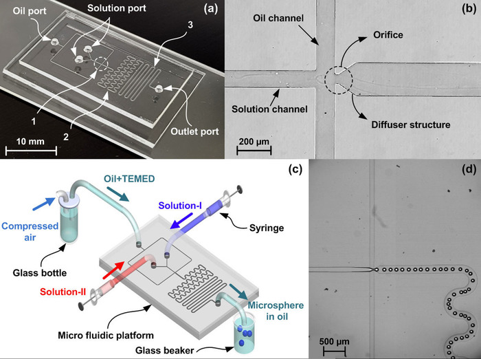
Figure 1: The microfluidic platform. (a) Fabricated microfluidic platform, (b) enlarged view of the flow-focusing geometry, (c) experimental set-up, and (d) Captured images showing continuous generation of microspheres. 1: Micro channel structure for flow focusing geometry, 2: for mixing solutions, 3: for microsphere solidification. Please click here to view a larger version of this figure.
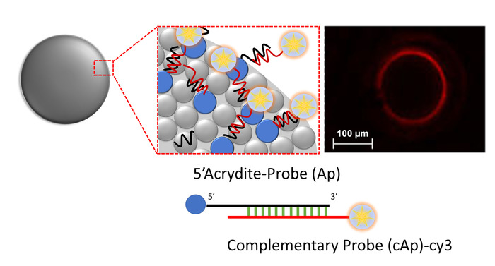
Figure 2: Fluorescent readout of DNA hybridization on the surface of microspheres. 5'-Acrydite-modified DNA probes (Ap) were capable of hybridizing with complementary Cy3 labeled DNA probes (cAp). Please click here to view a larger version of this figure.

Figure 3: Illustration of the microsphere-PCR protocol. Please click here to view a larger version of this figure.

Figure 4: Comparison between conventional asymmetric PCR and microsphere-PCR. M; ssDNA marker (76mer and 100mer), Lane 1; Asymmetric PCR, Lane 2; Microbeads-PCR. Reprinted with permission from previous work8. Please click here to view a larger version of this figure.
| Reagent | Volume in mix (μL) | Final Concentration | |
| Solution I | 40% Acrylamide:bis solution (19:1) | 25 | 10% |
| 100 μM Acrydite probe (Ap, 5’-Acrydite-(TTTTTTT, linker sequence) AGA TTG CAC TTA CTA TCT-3’) | 10 | 10 μM | |
| 5X TBE buffer (Tris-base-EDTA) | 10 | 0.5X | |
| Water | 5 | - | |
| Solution II | 20% Ammonium persulfate | 50 | 10% |
| Solution III | TEMED (N,N,N′,N′-Tetramethylethylenediamine) | 8 | 0.40% |
| Mineral oil | 1000 | - | |
Table 1. Reagent mix components for on-flow polyacrylamide microsphere synthesis.
| Operational condition | Microsphere production speed | |
| Solution flowrate | Oil pressure | |
| (mL/h) | (kPa) | ( / sec) |
| 0.4 | 82 | 7.1 |
| 0.5 | 94 | 13.3 |
| 0.6 | 108 | 28.9 |
| 0.7 | 116 | 36.5 |
Table 2. Summary of operational conditions and produced microsphere.
| DNA probe | Sequences |
| Cy3 labeled complementary oligonucleotide probe (cAp) | 5’-Cy3-AGATAGTAAGTGCAATCT-3’ |
| Tag (first 24 nt)-forward primer | 5’- GGT AAT ACG ACT CAC TAT AGG GAG ATA CCA GCT TAT TCA ATT-3’ |
Table 3. Sequence information of DNA probes.
| Reagent | Volume for 1x reaction (μL) | Final concentration |
| Random DNA template | 1 | 1 ng/μL |
| Tag-forward primer | 1 | 0.4 μM |
| Reverse primer | 1 | 0.02 μM |
| 10X Taq buffer | 5 | 1X |
| 10 mM of dNTP | 4 | 2.5 mM |
| Ex taq (1000U) | 0.2 | 1 U |
| Water | 37.8 | - |
| Total | 50 | - |
Table 4. Asymmetric PCR reagent mix components in 20 μL reaction.
| Template | Sequence | Length (nt) |
| Random DNA template | 5’- ATA CCA GCT TAT TCA ATT (Random sequence, 40 mer) AGA TAG TAA GTG CAA TCT-3’ | 76 |
| Tag-Forward primer (Tag-F) | 5’- GGT AAT ACG ACT CAC TAT AGG GAG ATA CCA GCT TAT TCA ATT-3’ | 42 |
| Reverse primer | 5’- AGA TTG CAC TTA CTA TCT-3’ | 18 |
Table 5. Sequence information for Microsphere-PCR.
| Reagent | Volume for 1x reaction (μL) | Final concentration |
| Ap-Microspheres | ~25 microspheres | - |
| Random DNA template | 1 | 1 ng/μL |
| Tag-Forward primer | 1 | 0.4 μM |
| 10X Taq buffer | 5 | 1X |
| 10 mM dNTP | 4 | 2.5 mM |
| Ex taq (1000U) | 0.2 | 1 U |
| Water | 37.8 | - |
| Total | 50 | - |
Table 6. Microsphere-PCR reagent mix components in 50 μL reaction.
| Scan mode | Plane |
| Scaling | X: 2.49 μm, Y: 2.49 μm |
| Stack size | X: 1272.79 μm, Y: 1272.79 μm |
| Scan zoom | 0.7 |
| objective | EC Plan-Neofluar 10 x / 0.3 M27 |
| Average | 1 |
| Pinhole | Ch2: 104 um |
| Filters | Ch3: LP 420 |
| Beam splitters | MBS: HFT 488 / 543, DBS1: mirror, DBS2: NFT 515, FW1: None |
| Wavelength | 543 nm 100.0 % |
Table 7. Settings for the confocal microscope.
Discussion
Loading...
$$\rightleftharpoonup{xx}$$
$$\longleftharp{xx}$$,
$$\longrightharp{xx}$$,
Contaminants of dsDNA are a major issue in ssDNA amplification. It remains difficult to minimize dsDNA amplification in conventional asymmetric PCR amplification15. In addition, although technical improvements for generating ssDNA have enabled us to increase the efficiency of sample throughput, ssDNA isolation is still problematic due to its high costs and incomplete purification yields.
Asymmetric PCR is one of the most challenging methods used when working with ssDNA. This method applies unequal amounts of primer (e.g., 20: 1 ratio) in order to generate large amounts of ssDNA. However, it is very difficult to optimize every amplification reaction to yield ssDNA. Thus, the byproducts (dsDNA) must be eliminated from the resultants4.
In order to generate ssDNA without additional separation steps, we produced polyacrylamide microspheres to expose DNA probes based on the acrydite copolymerization method. Our DNA attachment method was easily adapted by using a droplet-based microfluidic platform. Copolymerized oligomicrospheres having microscale diameters were successfully produced. Consequently, microsphere-PCR was used to amplify the ssDNA in a single-tube reaction. Of course, to adapt this procedure for other PCR experiments, commonly necessary adjustments (e.g., changing the amplification cycle, annealing temperature, and template sequences) are required. In conclusion, microsphere-PCR has been detailed here, making it available for bioassay development, DNA sequencing, and DNA microarray analysis.
Disclosures
Loading...
$$\rightleftharpoonup{xx}$$
$$\longleftharp{xx}$$,
$$\longrightharp{xx}$$,
The authors have no conflicts of interest to disclose.
Acknowledgements
Loading...
$$\rightleftharpoonup{xx}$$
$$\longleftharp{xx}$$,
$$\longrightharp{xx}$$,
This study is supported by a project entitled "Cooperative Research Program for Agriculture Science & Technology Development (Project No. PJ0011642)" funded by the Rural Development Administration, Republic of Korea. This research was also partly supported by a grant (NRF-2017R1A2B4012253) of the Basic Science Research Program through the National Research Foundation (NRF) funded by the Ministry of Science, ICT & Future Planning, Republic of Korea. This research was also supported by a grant (N0000717) of the Education program for Creative and Industrial Convergence funded by the Ministry of Trade, Industry and Energy, Republic of Korea.
Materials
| Name | Company | Catalog Number | Comments |
|---|---|---|---|
| liquid polydimethylsiloxane, PDMS | Dow Corning Inc. | Sylgard 184 | Components of chip |
| 40% Acrylamide:bis solution (19:1) | Bio-rad | 1610140 | Components of Copolymerizable oligo-microsphere |
| Ammonium persulfate, APS | Sigma Aldrich | A3678 | Hardener of acrylamide:bis solution |
| N,N,N′,N′-Tetramethylethylenediamine, TEMED | Sigma Aldrich | T9281 | Catalyst of ammonium persulfate |
| Mineral oil | Sigma Aldrich | M5904 | Table 1. Solution III. Component of microsphere reagents |
| Cy3 labeled complementary oligonucleotide probes | Bioneer | synthesized | Table 3. Sequence information |
| ssDNA acrydite labeled probe | Bioneer | synthesized | Table 1. Solution I. Component of microsphere reagents |
| Tris | Biosesang | T1016 | Components of TE buffer, pH buffer solution |
| EDTA | Sigma Aldrich | EDS | Components of TE buffer, removal of ion (Ca2+) |
| Ex taq | Takara | RR001A | ssDNA amplification |
| Confocal microscope | Carl Zeiss | LSM 510 | Identifying oligonucleotides expossure of microsphere surface |
| Light Microscope | Nikon Instruments Inc. | eclipse 80i | Caculating number of microspheres |
| T100 Thermal Cycler | Bio-rad | 1861096 | ssDNA amplification |
| Hand-held Corona Treater | Electro-Technic | BD-20AC Laboratory Corona Treater | Hydrophilic surface treatment |
| Hot plate | As one | HI-1000 | heating plate for curing of liquid PDMS |
| Syringe pump | kd Scientific | 78-1100 | Uniform flow of Solution I and Solution II |
| Compressor | Kohands | KC-250A | Flow control of Solution III |
| Bright-Line Hemacytometer | Sigma Aldrich | Z359629 | Caculating number of microspheres |
References
Loading...
$$\rightleftharpoonup{xx}$$
$$\longleftharp{xx}$$,
$$\longrightharp{xx}$$,
- The use of exonuclease III for preparing single stranded DNA for use as a template in the chain terminator sequencing method. Nucleic Acids Research. 6 (3), 831-848 (1979).">Smith, A. J. The use of exonuclease III for preparing single stranded DNA for use as a template in the chain terminator sequencing method. Nucleic Acids Research. 6 (3), 831-848 (1979).
- Aptabody-aptatope interactions in aptablotting assays. Nanoscale. 9 (22), 7464-7475 (2017).">Sekhon, S. S., et al. Aptabody-aptatope interactions in aptablotting assays. Nanoscale. 9 (22), 7464-7475 (2017).
- Profiling RNA polymerase-promoter interaction by using ssDNA-dsDNA probe on a surface addressable microarray. Chembiochem. 8 (14), 1667-1670 (2007).">Ng, J. K., Ajikumar, P. K., Stephanopoulos, G., Too, H. P. Profiling RNA polymerase-promoter interaction by using ssDNA-dsDNA probe on a surface addressable microarray. Chembiochem. 8 (14), 1667-1670 (2007).
- Defining the copper binding aptamotif and aptamer integrated recovery platform (AIRP). Nanoscale. 9 (8), 2883-2894 (2017).">Sekhon, S. S., et al. Defining the copper binding aptamotif and aptamer integrated recovery platform (AIRP). Nanoscale. 9 (8), 2883-2894 (2017).
- Effects of Xenopus laevis mitochondrial single-stranded DNA-binding protein on primer-template binding and 3'-->5' exonuclease activity of DNA polymerase gamma. Journal of Biological Chemistry. 271 (31), 18939-18946 (1996).">Mikhailov, V. S., Bogenhagen, D. F. Effects of Xenopus laevis mitochondrial single-stranded DNA-binding protein on primer-template binding and 3'-->5' exonuclease activity of DNA polymerase gamma. Journal of Biological Chemistry. 271 (31), 18939-18946 (1996).
- On-demand one-step synthesis of monodisperse functional polymeric microspheres with droplet microfluidics. Langmuir. 31 (13), 3982-3992 (2015).">Yu, X., Cheng, G., Zhou, M. D., Zheng, S. Y. On-demand one-step synthesis of monodisperse functional polymeric microspheres with droplet microfluidics. Langmuir. 31 (13), 3982-3992 (2015).
- Membrane-Integrated Glass Capillary Device for Preparing Small-Sized Water-in-Oil-in-Water Emulsion Droplets. Langmuir. 31 (25), 7166-7172 (2015).">Akamatsu, K., Kanasugi, S., Nakao, S., Weitz, D. A. Membrane-Integrated Glass Capillary Device for Preparing Small-Sized Water-in-Oil-in-Water Emulsion Droplets. Langmuir. 31 (25), 7166-7172 (2015).
- On-Flow Synthesis of Co-Polymerizable Oligo-Microspheres and Application in ssDNA Amplification. PLoS One. 11 (7), e0159777(2016).">Lee, S. H., et al. On-Flow Synthesis of Co-Polymerizable Oligo-Microspheres and Application in ssDNA Amplification. PLoS One. 11 (7), e0159777(2016).
- Formation of dispersions using "flow focusing" in microchannels. Applied Physics Letters. 82 (3), 364-366 (2003).">Anna, S. L., Bontoux, N. B., Stone, H. A. Formation of dispersions using "flow focusing" in microchannels. Applied Physics Letters. 82 (3), 364-366 (2003).
- Droplet formation via squeezing mechanism in a microfluidic flow-focusing device. Computers & Fluids. 100, 218-226 (2014).">Gupta, A., Matharoo, H. S., Makkar, D., Kumar, R. Droplet formation via squeezing mechanism in a microfluidic flow-focusing device. Computers & Fluids. 100, 218-226 (2014).
- Poly(dimethylsiloxane) as a material for fabricating microfluidic devices. Accounts of Chemical Research. 35 (7), 491-499 (2002).">McDonald, J. C., Whitesides, G. M. Poly(dimethylsiloxane) as a material for fabricating microfluidic devices. Accounts of Chemical Research. 35 (7), 491-499 (2002).
- PDMS bonding by means of a portable, low-cost corona system. Lab on a Chip. 6 (12), 1548-1549 (2006).">Haubert, K., Drier, T., Beebe, D. PDMS bonding by means of a portable, low-cost corona system. Lab on a Chip. 6 (12), 1548-1549 (2006).
- Integrated Microfluidic Selex Using Free Solution Electrokinetics. Journal of the Electrochemical Society. 164 (5), B3122-B3129 (2017).">Olsen, T. R., et al. Integrated Microfluidic Selex Using Free Solution Electrokinetics. Journal of the Electrochemical Society. 164 (5), B3122-B3129 (2017).
- Oligodeoxyribonucleotide probe accessibility on a three-dimensional DNA microarray surface and the effect of hybridization time on the accuracy of expression ratios. BMC Biotechnology. 3, 6(2003).">Dorris, D. R., et al. Oligodeoxyribonucleotide probe accessibility on a three-dimensional DNA microarray surface and the effect of hybridization time on the accuracy of expression ratios. BMC Biotechnology. 3, 6(2003).
- Essential strategies to optimize asymmetric PCR conditions as a reliable method to generate large amount of ssDNA aptamers. Biotechnology and Applied Biochemistry. 64 (4), 541-548 (2017).">Heiat, M., Ranjbar, R., Latifi, A. M., Rasaee, M. J., Farnoosh, G. Essential strategies to optimize asymmetric PCR conditions as a reliable method to generate large amount of ssDNA aptamers. Biotechnology and Applied Biochemistry. 64 (4), 541-548 (2017).
Reprints and Permissions
Request permission to reuse the text or figures of this JoVE article
Request Permission