

Summary
A method called negative additive manufacturing is used to produce near fully dense complex shaped boron carbide parts of various length scales. This technique is possible via the formulation of a novel suspension involving resorcinol-formaldehyde as a unique gelling agent that leaves behind a homogenous carbon sintering aid after pyrolysis.
Abstract
Boron carbide (B4C) is one of the hardest materials in existence. However, this attractive property also limits its machineability into complex shapes for high wear, high hardness, and lightweight material applications such as armors. To overcome this challenge, negative additive manufacturing (AM) is employed to produce complex geometries of boron carbides at various length scales. Negative AM first involves gelcasting a suspension into a 3D-printed plastic mold. The mold is then dissolved away, leaving behind a green body as a negative copy. Resorcinol-formaldehyde (RF) is used as a novel gelling agent because unlike traditional hydrogels, there is little to no shrinkage, which allows for extremely complex molds to be used. Furthermore, this gelling agent can be pyrolyzed to leave behind ~50 wt% carbon, which is a highly effective sintering aid for B4C. Due to this highly homogenous distribution of in situ carbon within the B4C matrix, less than 2% porosity can be achieved after sintering. This protocol highlights in detail the methodology for creating near fully dense boron carbide parts with highly complex geometries.
Introduction
Boron carbide (B4C), with a Vickers hardness of about 38 GPa, is known as the third hardest commercially available material, behind diamond (~115 GPa) and cubic boron nitride (~48 GPa). This particular property, along with a low density (2.52 g/cm3), makes it attractive for defense applications such as armors1. B4C also has a high melting point, superior wear resistance, and high neutron absorption cross section2,3,4. However, utilization of these favorable mechanical properties typically requires B4C to be sintered to a high density. Hot pressing is a conventional method for sintering B4C to full densification. This technique is often limited to simple geometries with limited curvature and fairly uniform thickness. Expensive and labor-intensive machining with polycrystalline diamond tooling or laser cutting is required to introduce finer or more complex features.
Alternatively, colloidal forming techniques with pressure-less sintering can produce near-full density parts that require minimal to no machining. Due to a lack of external pressure during consolidation, sintering aids are normally added to the ceramic medium to increase the effectiveness of pressureless sintering. Carbon is commonly used as a sintering aid for B4C5,6,7.Various carbon sources, such as nanoparticle powders or carbonized organics from pyrolysis, can be used. Homogeneous distribution of the carbon sintering aid along grain boundaries is an important factor for obtaining uniform sintering of B4C. Therefore, carbon concentration and B4C particle size are also important and interrelated factors for sintering parts to high density8.
One of the most promising colloidal forming techniques for obtaining complex shaped ceramic parts is gelcasting. This technique involves casting a ceramic suspension with an organic monomer into a mold which polymerizes in situ to act as a gel9,10,11. The gel serves as a binder to form a green body in the shape of the mold that is strong enough to be handled without breakage in subsequent processing steps. Previously impossible 3D mold geometries can now be produced through low-cost polymer-based additive manufacturing (AM) techniques such as stereolithography (SLA) and fused deposition modeling (FDM)12. The recent availability of 3D printers has opened new possibilities for designing ceramics with highly complex geometries.
Negative additive manufacturing is a technique that combines gelcasting with sacrificial 3D-printed molds. The complexity of the ceramic part is directly related to the complexity of the mold design. Mold designs can now be incredibly sophisticated with the advent of high resolution plastic 3D printers. For example, 3D scanning tools can be used to capture an individual's contours and be incorporated into molds. By using negative AM, lightweight ceramic armors tailored to the individual's body size and shape can be created. Such design customizations can provide lighter weight armors with enhanced mobility for users.
Other common ceramic AM techniques such as direct ink write (DIW), selective laser sintering (SLS), and binder jetting (BJ) are also effective in producing complex shaped ceramic parts. However, most of these techniques are only useful for producing fine porous structures and are not efficient when scaling up to large parts, such as armor applications13,14,15,16,17. Moreover, most of these techniques are not feasible for high volume production due to high expenses. Therefore, negative AM is a preferred and relatively inexpensive route for industrial-level production of large-scale parts.
The B4C suspensions used for gelcasting must be low in viscosity and contain a gelling agent and sintering aid. Resorcinol and formaldehyde are chosen for their ability to undergo polycondensation reactions to form a resorcinol-formaldehyde (RF) network, which helps to bind the B4C particles together. Traditional hydrogels used for gelcasting are limited to molds with hollow cores due to the high inward shrinkage experienced during the drying process18. Since RF is commonly used as an aerogel, there is little to no shrinkage, which permits the use of more intricately shaped molds. Another advantage of using RF is that the gelation rate can be controlled by altering the pH of the suspension (Figure 3). Additionally, suspensions containing either resorcinol or formaldehyde can be prepared in advanced and stored separately until they are ready for casting. Most importantly, the RF gel can be pyrolyzed to leave behind 50 wt% carbon19. This highly homogenous distribution of carbon can aid the densification of B4C to near-full densities during sintering. 15 wt% of RF relative to boron carbide is used in the formulation of the suspension to provide 7.5 wt% of carbon after pyrolysis of the cast parts.
The overall goal of this work is to combine traditional gelcasting techniques with inexpensive 3D printing capabilities and a unique gelling agent to obtain near-full density boron carbide parts with highly complex geometries. In addition to ceramics, negative AM can be applied to other material fields to create entirely new geometries of multi-material systems. The methodology described here expands on the work presented in Lu et al.8 and aims to provide a more detailed protocol for reproducing those results.
Subscription Required. Please recommend JoVE to your librarian.
Protocol
CAUTION: Please consult with the safety data sheets (SDS) of all materials, and wear proper protective equipment (PPE) when handling materials before casting and curing. Resorcinol and polyethylene imine are known to be toxic. Formaldehyde is both toxic and carcinogenic20. Preparation of ceramic suspensions should be done in chemical fume hoods or other properly ventilated work environments.
1. Negative Additive Manufacturing
- Preparation of a 120 mL two-part suspension
NOTE: A two-part suspension will be prepared to help prolong the shelf life of the suspensions before casting. One suspension (R-mix) will contain the resorcinol component, and the other (F-mix) will contain the formaldehyde component. Both suspensions will be mixed together to form a final suspension that will initiate the gelation process.- To create the R-mix, begin by dissolving 0.88 g of polyethylene imine (PEI) in 25.00 g of water using a planetary mixer.
- To create a separate F-mix, dissolve 0.88 g of polyethylene imine (PEI) in 16.83 g of water using a planetary mixer.
NOTE: Using a planetary mixer at 2000 rpm for at least several minutes will provide sufficient shearing forces to help dissolve the viscous PEI, resorcinol, and formaldehyde, and to suspend the boron carbide particles. PEI serves as the dispersing agent for the B4C particles - Dissolve 12.60 g of resorcinol powder into the R-mix. The solution should turn from a cloudy-white to a clear transparent solution after complete dissolution of the powder from mixing.
- Add 17.03 g of formaldehyde solution to the F-mix and ensure complete mixing.
- Incrementally add 5.25 g (12 increments until reaching 63.00 g) of boron carbide powder (1500F) into both the R-mix and F-mix separately.
- Add 6.50 g of acetic acid to the R-mix and F-mix and ensure complete mixing in each.
NOTE: At this point, the two-part suspensions will have 42 vol% of B4C and are ready to be combined for casting or stored for future use (if adequately sealed). Beware that if the suspensions sit for ~1 h or more, particle settling will occur. Ensure that the particles are resuspended by applying thorough agitation before using the suspensions. Also, three different commercial batches of boron carbides, 1250F, 1500F, and 3000F (named according to their approximate sieved mesh sizes), were originally tested. Each batch has a different particle size distribution, and the 1500F B4C batch was found to achieve the highest sintering density, as reported in Lu et al.8. Acetic acid can also be added before the B4C solids loading step as well, but adding at the end offers better ease of handling by limiting acetic acid odors.
- Preparation of the 3D printed molds for casting
- Prepare the mold design in a computer-aided design (CAD) software program.
- Print the molds using a Fused Deposition Modeling (FDM) 3D printer with acrylonitrile butadiene styrene (ABS) filaments.
NOTE: Acetone vapors can be used to smooth out the mold texture if desired21. The suggested nozzle and bed temperatures are 240 °C and 110 °C, respectively. Parameters such as layer thickness (0.2 mm), extrusion speed, and cooling rate are chosen to optimize the quality of the part with minimum deformations. This requires some trial and error with each unique printer system. A wall thickness of at least 1 mm is advised. The minimum feature size is 0.5 mm; however, it is suggested not to go below 1 mm. Molds from Lu et al.8 are available for download online in supporting material.
- Combination of the two-part suspension to prepare for casting
- Before combining, thoroughly agitate (by using a vortex or planetary mixer) the R-mix with the F-mix suspensions individually to ensure the B4C particles are well-suspended.
- Combine the R-mix and F-mix to obtain the final suspension.
NOTE: The pH of the combined suspension should be 2.8, which will provide about 30 minutes of working time to de-air and cast the final suspension before gelation starts occurring. The onset of gelation can be observed from the sharp increase in viscosity of the suspension. - Before casting, mix and apply vacuum (20-200 torr or 2.7-27 kPa) to the final suspension mixture for about 10 minutes to remove air bubbles without boiling the water. This can be accomplished by using a stirring plate at 200-300 rpm with a vacuum jar.
- Gelcasting
- Immediately pour the de-aired suspension into the 3D-printed molds.
- Place the molds inside a sealed glass container to prevent moisture loss during the curing process.
- Place the sealed container with the molds into a 60-80 °C oven to initiate the curing process.
- Allow the casts to cure for at least 8 hours for parts that are several centimeters in length scale or possibly longer for larger molds.
- Dissolution of the molds to obtain green bodies
- Remove the sealed container with the molds from the oven and allow it to cool to room temperature.
- Add enough acetone into the container until the mold is fully submersed. The amount will vary depending on the size and volume of the mold used (generally ~100 mL of acetone for a mold that is 50 cm3 in dimension).
NOTE: This process may take up to 2-4 days depending on the volume of plastic that needs to be dissolved away. Minimal agitation of the acetone bath or heating it slightly to 40 °C may help speed up the process. Execute caution when heating acetone bath, as it is a flammable chemical and may become explosive when combined with air in certain composition ranges. - Extract the free green body from the acetone bath after the ABS plastic is dissolved away.
NOTE: After the RF is cured, the mold can be dissolved away to obtain a solid green body shaped as a negative copy of the inner mold geometry. This green body should be strong enough to survive gentle and careful handling in the subsequent post-processing steps without breaking. - Place the green bodies in an oven at 80 °C to ensure complete drying and removal of all moisture.
NOTE: Drying time varies depending on the volume of the green body. Leaving the part to dry overnight (> 8 hours) is sufficient for green body sizes less than 1000 cm3. There is no harm in over-drying.
2. Carbonization
- After drying, place each green body in a 2-inch quartz tube lined with graphite foil and put them into a furnace with flowing gas [250 standard cubic centimeters of air (SCCM) consisting of 4 wt% H2(g) and 96 wt% Ar(g) to create a reducing atmosphere during the pyrolysis treatment].
- Heat the green bodies inside the furnace at 5 °C/min until 1050 °C and hold for 3 hours.
NOTE: The gel-cast green bodies will have 15 wt% of RF relative to the B4C and will provide about 7.5 wt% in carbon after the pyrolysis process. This process removes much of the resorcinol-formaldehyde residue and will severely contaminate the furnace if no trap is used. - Ensure that the green bodies come out uniformly darker in color, indicating the presence of carbon from the pyrolysis treatment.
3. Sintering
NOTE: After sintering, the surface roughness of the samples will improve slightly compared to the surface roughness of the molds used. This is a consequence of the 57-58 vol% shrinkage of the samples from sintering.
- Place the carbonized parts in a graphite furnace with vacuum backfilled flowing helium gas (420 SCCM) for sintering. Apply 280 SCCM to the front and pyrometer windows and 140 SCCM directly into the sample chamber with an inlet pressure of ~170 kPa.
- Heat up the furnace to 2290 °C (20 K/min to 2000 °C then 3 K/min to 2290 °C) and hold for 1 hour to achieve optimal densification of the parts.
NOTE: Archimedes density is a common and quick technique to measure the density of the sintered boron carbide parts. Archimedes density kits can be added onto analytical balance scales to measure the density of samples or manually determined22. Boron carbide with 7.5 wt% in carbon will have a theoretical maximum density (TMD) of 2.49 g/cm3. Parts sintered at 2290 °C from this methodology will result in 2.43 ± 0.01 g/cm3 which is 97.6 ± 0.4% TMD.
Subscription Required. Please recommend JoVE to your librarian.
Representative Results
Following the outlined procedure (Figure 1), complex shaped boron carbide parts with carbon (B4C/C) can be sintered up to 97.6 ± 0.4% of theoretical max density with a Vicker's hardness of 23.0 ± 1.8 GPa8. Several possible examples of sintered B4C/C parts are demonstrated (Figure 2). These examples show the fine textural features that can be copied by the gelcasting technique. This is advantageous for creating parts that require precise meso-scale features. Rheology of the final B4C suspension was determined for different pHs. A pH 2.8 suspension was measured as having the lowest viscosity for over 20 minutes, which is adequate for mixing, de-airing, and casting (Figure 3).
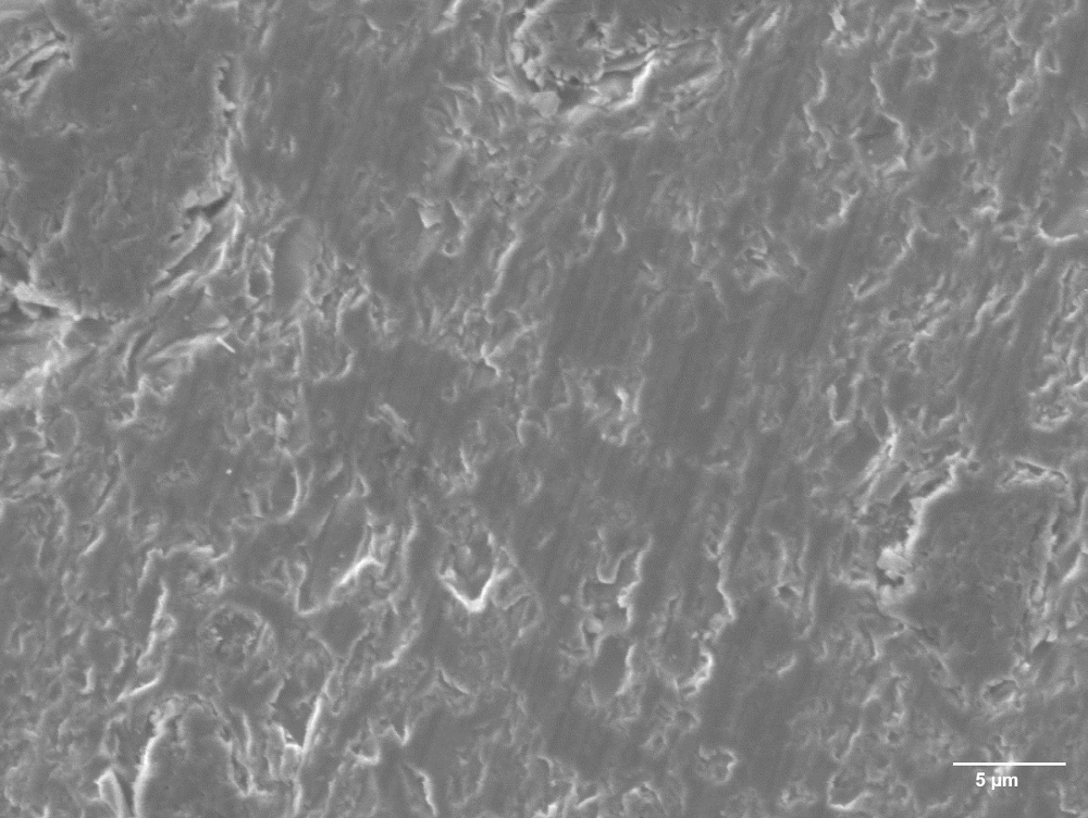
Further scanning electron microscopy indicated that uniform networks of carbon are coated onto the B4C particles after the pyrolysis of RF (Figure 4A and 4B). After casting and post-heat treatment steps, characterization using X-ray diffraction (XRD) confirmed the evolution of carbon as graphite (Figure 4C). Microstructural image of a fully sintered boron carbide sample revealed low porosity in the final part, which is highly desirable (Figure 5).

Figure 1: Depiction of the entire negative AM process for producing high density complex shaped boron carbides. This schematic provides a step-by-step overview of the entire fabrication process, from 3D printing of the mold to sintering of the final ceramic part. This figure has been modified with permission from Lu et al.8. Please click here to view a larger version of this figure.

Figure 2: Sintered complex shaped B4C/C parts with >97% density prepared from negative AM. (a) Gyroid; (b) Celtic Knot; (c) Cubic Lattice. The slight textural difference for each shape is due to differences in the quality of the 3D-printed molds used (dark black regions are carbon residues left on the surface after pyrolysis of the molds and can be rubbed off). This figure has been modified with permission from Lu et al.8. Please click here to view a larger version of this figure.

Figure 3: Rheology of the final B4C suspension. (a) Complex viscosity as a function of time for different pH suspensions with B4C and resorcinol-formaldehyde. Thickening is defined as the viscosity at 1 Pa∙s. (b) Time to reach thickening for the different pH suspensions. This figure has been modified with permission from Lu et al.8. A rheometer with attached parallel circular plates at a constant 30% oscillation strain and 1 Hz frequency was used to measure complex viscosity. All samples were measured at room temperature except for one pH 2.8 sample where the environmental temperature chamber in the instrument was used to provide heat (16.2 °C/min) until 80 °C was reached. Please click here to view a larger version of this figure.

Figure 4: Scanning electron microscopy and XRD were used to identify the presence of carbon network within the boron carbide matrix after RF gel pyrolysis. Boron carbide 1500F particles (a) without carbon coating and (b) with 7.5 wt% carbon coating are shown. (c) XRD of different thermal treatment stages of the B4C cast. This figure has been modified with permission from Lu et al.8. XRD spectra were collected on an X-ray diffractometer. Samples were mounted on a polymer clay and leveled flat. A LynxEye 1-dimensional linear Si strip detector was used with a variable divergence slit of 6 mm and a 0.5° anti-scatter slit. The source was Ni-filter Cu radiation (λ = 1.5406 Å) from a sealed X-ray tube operated at 40 kV and 40 mA. The source and detector were stepped scanned together at fixed angles from the sample with a combined 2θ of 20-80° at a rate of 0.02°/s. Post-processing algorithms from the XRD analysis software were used to strip away contributions from background noise and the K-alpha 2 radiation. A scanning electron microscope at 10.0 kV accelerating voltage on secondary electron mode was used to image the B4C particles. Please click here to view a larger version of this figure.

Figure 5: A saw-cut cross-sectional surface of a 2290 °C sintered 1500F boron carbide sample at ~97% density. This figure has been modified with permission from Lu et al.8. Please click here to view a larger version of this figure.
Subscription Required. Please recommend JoVE to your librarian.
Discussion
The methodology of negative additive manufacturing described in the protocol allows complex shaped boron carbide parts to be produced at nearly full density after sintering at an optimal temperature of 2290 °C. The first several steps related to preparation and casting are the most critical for generating a high-quality cast with minimal defects. If the viscosity of the suspension is too high, poor mixing will occur. The porosity of the sintered part is also affected since increased viscosity hinders air bubble removal. If the final suspension has been sitting idle for too long after mixing and de-airing, the increase in viscosity will be problematic for filling in small cavities in irregularly shaped 3D-printed molds.
Another issue to be aware of is Stoke's settling effect in the aqueous suspensions. If the suspension viscosity is sufficiently low after casting and not immediately cured, boron carbide particles in the suspensions will settle, causing a concentration gradient in the green bodies. Improperly cast parts will deform, with higher shrinkage at the top compared to the bottom during sintering. To remedy this problem, boron carbide with multi-modal particle size distributions can be utilized to minimize non-uniform shrinkage issues during sintering. The gelation rate of RF, which is highly dependent on the pH and temperature of the mixture, is another important factor to consider. Higher pH and temperatures correspond to faster polymerization kinetics, which will be observed as an increase in viscosity of the suspension. Reducing the pH of suspensions allows for longer working time during casting and also for curing to be initiated instantaneously as a thermal set.
Although negative AM is an easily scalable technique for high volume production of large complex shaped parts, this method is limited in producing miniature parts. Green bodies of all ceramic casts have an inherent green strength. The green strength of a cast part will be weak if the dimensions are sufficiently small. For instance, a green body less than 1 mm thick will easily break from the internal shrinkage stresses during the curing process after casting compared to a green body that is greater than 10 mm thick. Therefore, the mold material's elasticity and stiffness are important parameters since higher shrinkage stresses will occur if a stiffer mold is used, due to thermal expansion of the mold from the 80 °C heat treatment. We have demonstrated that relatively soft molds such as hexanediol diacrylate (HDDA) can be used to produce highly ordered lattices with ~100 µm feature sizes without breakage and for creating meso-scale composites8,23.
In conclusion, negative AM is a simple technique that combines gelcasting with inexpensive plastic 3D printing to produce complex shaped ceramic parts. The advantage of the methodology described here is its ability to scale up for high volume production while being cost-effective. Future work will include higher B4C solids loading in suspensions to limit shrinkage during sintering. Mechanical testing is also underway to evaluate the strength properties of these materials. Nonetheless, negative AM is not limited to only the materials and systems presented in this protocol. Various gelling agents and 3D-printed molds from other AM techniques or materials can also be used. For example, Franchin et al.24 created porous sacrificial template molds with polyactic acid (PLA) using geopolymers as the inorganic component. These PLA sacrificial templates can be thermally removed when desired24. Therefore, the general technique described in this protocol can be applied to a vast domain of materials, which will open up new possibilities for the mass development of complex shaped ceramics, metals, and other composite systems.
Subscription Required. Please recommend JoVE to your librarian.
Disclosures
The authors have nothing to disclose.
Acknowledgments
This work was performed under the auspices of the U.S. Department of Energy by Lawrence Livermore National Laboratory under Contract DE-AC52-07NA27344. IM release LLNL-JRNL-750634.
Materials
| Name | Company | Catalog Number | Comments |
| Boron carbide powder 1250F | Tetrabor Ceramics | Lot 211M419 | >96% purity |
| Boron carbide powder 1500F | Tetrabor Ceramics | Lot 209M102/9 | >96% purity |
| Boron carbide powder 3000F | Tetrabor Ceramics | Lot 111m53/9 | >96% purity |
| Polyethylene Imine (PEI) | Sigma Aldrich | MKBP3417V | Averaged MW ~25,000 by L.S. |
| Resorcinol | Sigma Aldrich | MKBG6751V | BioXtra, ≥99% |
| Formaldehyde | Fisher Scientific | F79-1 | 37% by weight; Stabilized with 10-15% Methanol |
| Acetic Acid | Sigma Aldrich | SKU 695092 | Glacial ≥99.7% |
| Acetone | Sigma Aldrich | SKU 179124 | ACS Reagent Grade ≥99.5% |
| Water | LLNL In-house (Milli-Q) | ||
| Planetary Mixer | Thinky | AR-250 | Fits 150mL and 300mL Thinky containers |
| Acrylonitrile butadiene styrene (ABS) plastic filament | eSUN | Natural color | |
| Taz 6 (3D printer) | Lulzbot | FDM 3D printer | |
| 4%H2/96%Ar gas | Air Gas | UHP | 4% Hydrogen, balanced Argon |
| Helium gas | Air Gas | UHP | Helium |
| Heating oven | Neytech | Vulcan 9493308 | Oven for 80 °C curing |
| Quartz tube furnace | Applied Test Systems, Inc. | LEA 05-000075 | Furnace for 1050 °C carbonization |
| Graphite furnace | Thermal Technology LLC | Sintering furnace | |
| Scanning Electron Microscope (SEM) | Jeol | JSM-7401F | |
| pH meter | Thermo Scientific | Orion 4 Star | calibrated with buffer standards |
| Rheometer | TA Instrument | AR2000ex | For measurement of viscosity |
| X-ray Diffractometer (XRD) | Bruker | AX D8 Advanced | |
| Analytical balance | Mettler Toledo | XS104 | |
| Bruker EVA | XRD Analysis Software |
References
- An, Q. Prediction of superstrong τ -boron carbide phase from quantum mechanics. Physical Review B. 95 (10), 100101 (2017).
- Thévenot, F. Boron carbide - A comprehensive review. Journal of the European Ceramic Society. 6, 205-225 (1990).
- Lee, H., Speyer, R. F. Pressureless sintering of boron carbide. Journal of the American Ceramic Society. 86, 1468-1473 (2003).
- Deng, J. X. Erosion wear of boron carbide ceramic nozzles by abrasive air-jets. Materials Science and Engineering: A. 408, 227-233 (2005).
- Schwetz, K. A., Grellner, W. The influence of carbon on the microstructure and mechanical properties of sintered boron-carbide. Journal of Less-Common Metals. 82, 37-47 (1981).
- Elektroschmelzwerk Kempten Gmbh. Process for the production of dense sintered shaped articles of polycrystalline boron carbide by pressureless sintering. US. Schwetz, K. A., Vogt, G. , 4195066 (1980).
- Suzuki, H., Hase, T., Maruyama, T. Effect of carbon on sintering of boron carbide. Journal of the Ceramic Association, Japan. 87, 430-433 (1979).
- Lu, R., et al. Complex shaped boron carbides from negative additive manufacturing. Materials & Design. 148, 8-16 (2018).
- Omatete, O. O., Janney, M. A., Nunn, S. D. Gelcasting: From laboratory development toward industrial production. Journal of the European Ceramic Society. 17, 407-413 (1997).
- Yang, J., Yu, J., Huang, Y. Recent developments in gelcasting of ceramics. Journal of the European Ceramic Society. 31, 2569-2591 (2011).
- Gilissen, R., Erauw, J. P., Smolders, A., Vanswijgenhoven, E., Luyten, J. Gelcasting a near net shape technique. Materials & Design. 21, 251-257 (2000).
- Travitzky, N., et al. Additive manufacturing of ceramic-based materials. Advanced Engineering Materials. 16, 729-754 (2014).
- Zocca, A., Colombo, P., Gomes, C. M., Gunster, J. Additive Manufacturing of Ceramics: Issues, Potentialities, and Opportunities. Journal of the American Ceramic Society. 98, 1983-2001 (2015).
- Deckers, J., Vleugels, J., Kruthl, J. P. Additive Manufacturing of Ceramics: A Review. Journal of Ceramic Science and Technology. 5, 245-260 (2014).
- Costakis, W. J., Rueschhoff, L. M., Diaz-Cano, A. I., Youngblood, J. P., Trice, R. W. Additive manufacturing of boron carbide via continuous filament direct ink writing of aqueous ceramic suspensions. Journal of the European Ceramic Society. 36, 3249-3256 (2016).
- Colombo, P., Schmidt, J., Franchin, G., Zocca, A., Gunster, J. Additive manufacturing techniques for fabricating complex ceramic components from preceramic polymers. American Ceramic Society Bulletin. 96, 16-23 (2017).
- Olsson, A., Hellsing, M. S., Rennie, A. R. New possibilities using additive manufacturing with materials that are difficult to process and with complex structures. Physica Scripta. 92, 053002 (2017).
- Dhara, S., Kamboj, R. K., Pradhan, M., Bhargava, P. Shape forming of ceramics via gelcasting of aqueous particulate slurries. Bulletin of Materials Science. 25, 565-568 (2002).
- Lewicki, J. P., Fox, C. A., Worsley, M. A. On the synthesis and structure of resorcinol-formaldehyde polymeric networks - Precursors to 3D-carbon macroassemblies. Polymer. 69, 45-51 (2015).
- Swenberg, J. A., et al. Formaldehyde Carcinogenicity Research: 30 Years and Counting for Mode of Action, Epidemiology, and Cancer Risk Assessment. Toxicologic Pathology. 41, 181-189 (2013).
- Kuo, C. C., Chen, C. M., Chang, S. X. Polishing mechanism for ABS parts fabricated by additive manufacturing. The International Journal of Advanced Manufacturing Technology. 91, 1473-1479 (2017).
- Kires, M. Archimedes' principle in action. Physics Education. 42, 484-487 (2007).
- Zheng, X., et al. Design and optimization of a light-emitting diode projection micro-stereolithography three-dimensional manufacturing system. Review of Scientific Instruments. 83, 125001 (2012).
- Franchin, G., Colombo, P. Porous Geopolymer Components through Inverse Replica of 3D Printed Sacrificial Templates. Journal of Ceramic Science and Technology. 6, 105-111 (2015).
