A sitting platform has been developed and assembled that passively destabilizes sitting posture in humans. During the user's stabilizing task, an inertial measurement unit records the device's motion, and vibrating elements deliver performance-based feedback to the seat. The portable, versatile device may be used in rehabilitation, assessment, and training paradigms.
Method Article
A Vibrotactile Feedback Device for Seated Balance Assessment and Training
In This Article
Summary
Abstract
Postural perturbations, motion tracking, and sensory feedback are modern techniques used to challenge, assess, and train upright sitting, respectively. The goal of the developed protocol is to construct and operate a sitting platform that can be passively destabilized while an inertial measurement unit quantifies its motion and vibrating elements deliver tactile feedback to the user. Interchangeable seat attachments alter the stability level of the device to safely challenge sitting balance. A built-in microcontroller allows fine-tuning of the feedback parameters to augment sensory function. Posturographic measures, typical of balance assessment protocols, summarize the motion signals acquired during timed balance trials. No dynamic sitting protocol to date provides variable challenge, quantification, and sensory feedback free of laboratory constraints. Our results demonstrate that non-disabled users of the device exhibit significant changes in posturographic measures when balance difficulty is altered or vibrational feedback provided. The portable, versatile device has potential applications in rehabilitation (following skeletal, muscular, or neurological injury), training (for sports or spatial awareness), entertainment (via virtual or augmented reality), and research (of sitting-related disorders).
Introduction
Upright sitting is a prerequisite for other human sensorimotor functions, including skilled movements (e.g., typing) and perturbed balance tasks (e.g., riding on a train). To rehabilitate and improve sitting and related functions, modern balance training techniques are used: unstable surfaces perturb sitting1,2 and motion tracking quantifies balance proficiency3,4. Balance training outcomes improve when vibration is delivered to the body using patterns that match performance5. Such sensory feedback is evidently effective as a rehabilitation and training method; yet, current sensory feedback methods are geared towards standing balance and require laboratory-based equipment6,7.
The purpose of the work presented here is to build a portable device that can be sat upon and passively destabilized to various degrees while built-in instruments record its position and deliver vibrational feedback to the sitting surface. This combination of tools integrates previous work on wobble chairs2,4 and vibrational feedback5,6,7, making the benefits of these tools more powerful and accessible. Also presented are a procedure to train upright sitting and an analysis of the quantitative outcomes, following the established literature on posturographic measures8. These methods are appropriate for studying the effects of sitting balance exercise with an unstable surface when combined with vibrational feedback. Anticipated applications include sports training, general improvement of motor coordination, assessment of balance proficiency, and rehabilitation following skeletal, muscular, or neurological injury.
Protocol
All methods described here have been approved by the Health Research Ethics Board of the University of Alberta.
1. Construction and Assembly of Structural Components
- Construct an attachment interface for interchangeable hemispherical bases: weld a base nut to a steel weld plate.
- Use a computer numerical controlled (CNC) milling machine to construct a cylindrical chassis, lid, and base from polyethylene as shown in Figure 1. Bolt the base plate to the base and the base to the chassis.
NOTE: The mill features for attachment of bolts and other parts are according to the drawing files and 3D solid model files provided (see Supplementary Files 1 and 2). All structural components have a corresponding solid model and drawing that are available for download and can be used to replicate the construction process. - Use a milling machine to construct a cylindrical polyvinyl chloride sleeve that fits onto a threaded rod, as shown in Figure 1. Make the sleeve 37 mm long, with an outer diameter of 32 mm.
- Weld steel flanges to each side of a steel hitch, as shown in Figure 1. Bolt the hitch to the front of the base.
- Use a CNC turning machine to construct 5 identical cylinders from polyethylene, each with a height of 63 mm and a diameter of 152 mm. In the center of the top surface of each cylinder, cut a 32 mm hole to a depth of 38 mm so that it fits the cylindrical sleeve (see Step 1.3. above) with some interference.
- On the bottom surface of each cylinder, use a CNC turning machine to cut a uniformly curved base with a unique radius of curvature for each of the 5 cylinders, maintaining the overall height of 63 mm, as shown in Figure 2.
NOTE: The radius of curvature and height of the base determine the stability of the device. The suggested radii of curvature for this height are between 110 mm (very unstable) and 250 mm (slightly unstable), as shown in Table 1. - Construct a leg support attachment as shown in Figure 3, by first welding a 70 mm steel hitch insert perpendicularly to one end of a 575 mm steel extrusion. At the other end, clamp a 300 mm cylindrical steel footrest to the extrusion.
NOTE: For detailed part dimensions, see Supplementary File 1 (drawings) and Supplementary File 2 (3D solid models). - Use a bandsaw to cut a rectangular steel bar (29 mm by 100 mm) to a length of approximately 160 mm so that it weighs 3.6 kg. Insert the steel bar at the back of the chassis to counterbalance the leg support attachment, as shown in Figure 1.
- Assemble the device as shown in Figure 4. Connect the leg support by inserting clevis pins through the hitch and hitch insert. Adjust the location of the clamp to the desired foot rest height. Thread the rod into the base stud such that approximately 35 mm of the rod protrudes from the base. Insert the protruding rod into the desired curved base.
- Apply grip tape or another suitable upholstery to the lid. Put on the lid.
2. Instrumenting the Device
- Acquire a microcontroller (see the Table of Materials), an inertial measurement unit and eight vibrating tactors. Connect the inertial measurement unit and vibrating tactors to the microcontroller.
- Program the microcontroller such that it reads antero-posterior (AP) and medio-lateral (ML) tilt angles from the inertial measurement unit and turns the vibrating tactors on or off based on the tilt angles. See Supplementary File 3 (exemplary microcontroller script) and Step 2.2.1.
NOTE: Inertial measurement units that utilize accelerometers and gyroscopes are prone to error. Perform a positional calibration of the sensors: rest the device on a level surface and use this position as a baseline for all following measurements. Use a motion capture system or similar approach to validate the tilt angle measurements and ensure that they are sufficiently accurate throughout the expected range of use (spatial and temporal). Ensure the vibrating tactors operate at a frequency of no more than 200 Hz, so as to induce a one-to-one response of sensory receptors in human skin or muscle9.- Upload the microcontroller script that generates vibrotactile cues based on a feedback control signal that represents a weighted sum of AP (or ML) tilt angle and velocity.
NOTE: The computer activates three tactors closest to the left, right, front, or back of the surface when the control signal exceeds a threshold in that direction; or five tactors if an AP and ML threshold are surpassed simultaneously; none of the tactors are active when the control signal is below the threshold in both directions (i.e., in the no-feedback zone).
- Upload the microcontroller script that generates vibrotactile cues based on a feedback control signal that represents a weighted sum of AP (or ML) tilt angle and velocity.
- Secure the inertial measurement unit in the center of the chassis. Arrange the vibrating tactors on a regular octagon with a radius of 10 cm, centered 8 cm anterior of the center of the chassis so that they will lie under the seat of an average-sized person10. A photograph of one potential arrangement is shown in Figure 4.
NOTE: If the vibrating tactors are not powerful enough to vibrate the user, improve the interface between tactor and skin by cutting holes into the lid and fixating the vibrators to rest flush with the surface. If the method used to secure the vibrators in place causes dampening of the vibration, consider using a two-part mounting enclosure with a loose-fit locating pin, as shown in Figure 5. - Connect the microcontroller to a laptop or desktop computer via a universal serial bus (USB) or other suitable communication method. Open the user interface, shown in Figure 6.
NOTE: Alternatively, connect the microcontroller to a battery or other power source. This improves the portability of the device, but precludes a user interface.
3. Exemplary Assessment and Training Protocol
- Recruit consenting participants who are free of neurological or musculoskeletal disorders and acute or chronic back pain. Record each participant’s age, weight, and height. Then, for each participant, carry out the following procedure.
- Open the user interface (Figure 6). The compass graph shows the device’s tilt angle plus half its tilt velocity in the AP direction (vertical axis) and ML direction (horizontal axis).
- Prior to each balance trial, instruct the participant to don noise-cancelling headphones, fold his or her arms across the chest, maintain an upright posture as much as possible, and verbally cue the experimenter of being ready.
- Perform twenty 30 second seated balance trials in series11, taking breaks as warranted to avoid fatigue, stopping at any time if necessary.
- Sequence the trials as follows (example only): randomly select one of two “base stability level/eye condition” combinations, hereafter called balance conditions (more difficult base and eyes open; or less difficult base and eyes closed)12. Perform four trials of the first balance condition to familiarize the participant with the task and to identify appropriate control signal thresholds for the vibrating tactors in the seat (see Step 3.4.5 below).
NOTE: It is more difficult to maintain balance on a base with a small radius of curvature than on a base with a large radius of curvature (Table 1 shows the relative stability of all five interchangeable bases). Four trials have been found to be sufficient to achieve a stable performance of the balance task2. - Randomly select three of the next six trials to be control trials: switch the vibrating tactors off for the duration of these trials. To turn the vibrational feedback on or off, toggle the Feedback slider to the desired setting in the user interface. Repeat this sequence of ten trials for the second balance condition.
- Label the current difficulty and eye condition by selecting from the drop-down menus in the Trial Parameters section of the user interface. Click Record to start the trial.
NOTE: The participants’ safety is paramount. The experimenter should supervise all balance activities and be prepared to assist in the event of balance loss. Clear the area of any potential hazards and be aware of local emergency protocols. - For trials with eyes open, instruct the participant to focus on a fixed point straight ahead to help maintain balance. For trials with eyes closed, use a blindfold to ensure that the participant is completely deprived of visual feedback.
NOTE: For balance paradigms where the movement of the feet should be restricted, attach the foot support and insert the counterbalance beneath the lid. - An algorithm computes which AP and ML feedback thresholds to use and displays them in the Q3 column of the user interface. After four familiarization trials, copy the values shown in the Q3 column into the Write Column, and then click Refresh to update the feedback thresholds shown on the compass graph (pink) based on the fourth familiarization trial.
NOTE: The computed threshold values displayed in the Q3 column of the interface are equal to the third quartile for each tilt direction (AP, ML) during the previous trial. This feedback scheme is based on the notion that balance function is improved when feedback is optimized for each individual13,14, while providing too much feedback may detriment learning15. Once the two threshold values have been selected for a given individual, they can be kept constant for that individual to be able to assess improvements over time or with an intervention.
- Sequence the trials as follows (example only): randomly select one of two “base stability level/eye condition” combinations, hereafter called balance conditions (more difficult base and eyes open; or less difficult base and eyes closed)12. Perform four trials of the first balance condition to familiarize the participant with the task and to identify appropriate control signal thresholds for the vibrating tactors in the seat (see Step 3.4.5 below).
- As the AP and ML tilt angles are automatically stored, in real-time, in a text file for analysis, analyze the AP and ML signals to characterize sitting performance for each of the experimental conditions.
- In time domain, calculate the following posturographic measures from each time series8: root-mean-square (a measure of the variance of the motion) and the mean velocity (a measure of the average angular speed of the motion).
- In frequency domain, calculate the following posturographic measures from each time series8: centroidal frequency (a measure of the motion’s overall frequency) and frequency dispersion (a measure of the variance in the motion’s frequency)8.
- Use a linear mixed model to estimate and characterize the effects of two fixed-effects factors, (1) the balance condition (stability level and eye condition combined) and (2) vibrotactile feedback, on each of the posturographic measures (dependent variables), considering the correlation of repeated measurements from each participant16 (one random-effects factor).
- Test for significance of the fixed effects by computing the ratio of the variance between the group means to the variance of the residuals, and comparing the result to an F-distribution.
Results
Table 2 shows, for each experimental condition, the posturographic measures derived from observations of the AP and ML support surface tilts, averaged over 144 balance trials performed by 12 participants (2 x 2 x 3 trials per participant).
Effect of Changing the Balance Condition: The base condition was chosen to be dependent on the eye condition (i.e., when the eyes were closed, the base was more stable). Thus, the base and eye condition together were considered one independent variable (balance condition). Observations of AP tilt were significantly different between the two balance conditions for root-mean-square, centroidal frequency, and frequency dispersion (according to F-tests of the estimated change, α = 0.05). The computed change in each of the measures (mean and standard deviation) is shown in Figure 7 and Figure 8. Consistent with other reports, these posturographic measures can discriminate between balance tasks4.
Effect of Changing the Feedback Condition: During trials when the vibrotactile feedback system was active, the centroidal frequency of AP tilt observations was significantly higher than during the control trials (according to F-tests of the estimated change, α = 0.05). The computed change in each of the posturographic measures (mean and standard deviation) is shown in Figure 9 and Figure 10. Consistent with other reports, this vibrotactile feedback protocol has a measurable effect on balance performance17.
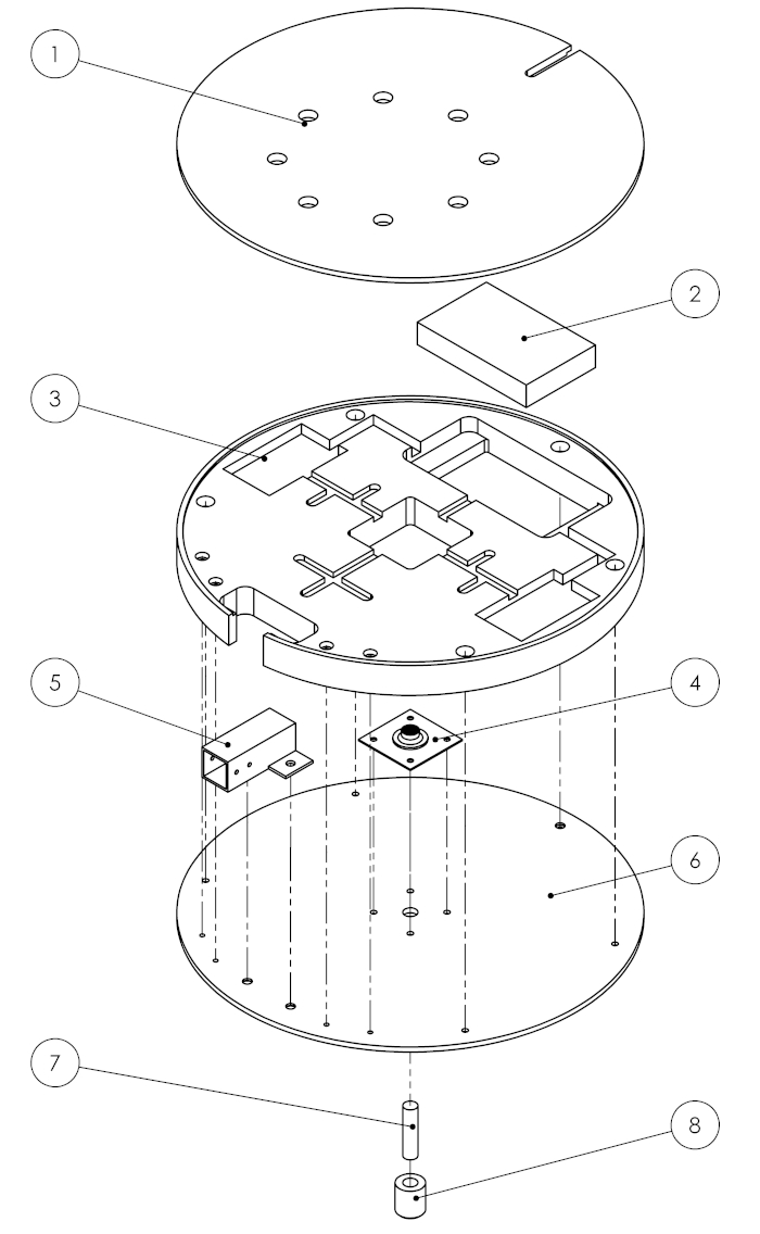
Figure 1: Exploded view of the chassis assembly. Structural components include: (1) lid; (2) counterweight; (3) cylindrical chassis; (4) base stud; (5) hitch for attachment of leg support attachment (Figure 3); (6) base; and (7,8) rod, and sleeve for attachment of one of five interchangeable cylinders (Figure 2). Please click here to view a larger version of this figure.
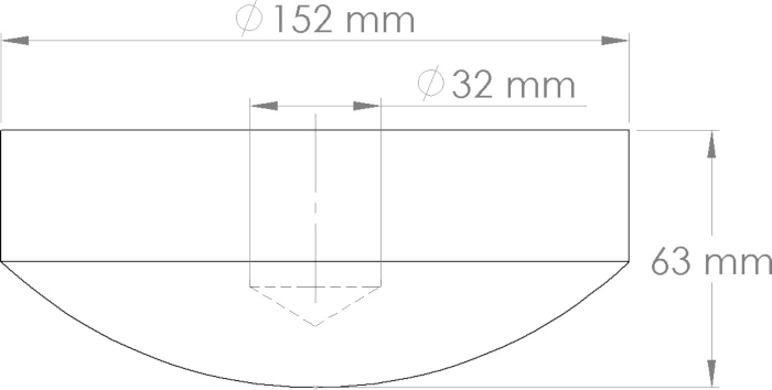
Figure 2: Side view of a curved base module. Each of the five modules has a total height of 63 mm and a unique radius of curvature, which modulates the difficulty of maintaining balance on the sitting surface. Please click here to view a larger version of this figure.
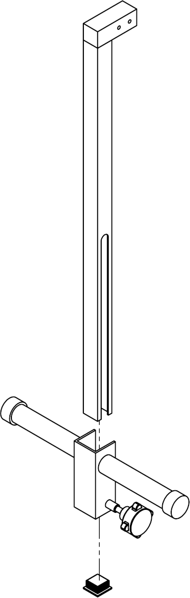
Figure 3: Exploded view of the leg support attachment. The leg support, consisting of a hitch, clamp, and square finishing plug, is 600 mm long and can be removed during transportation of the device or to permit the user to swing the legs freely during balance exercise. For detailed part dimensions, see Supplementary Files 1 (drawings) and 2 (3D solid models). Please click here to view a larger version of this figure.
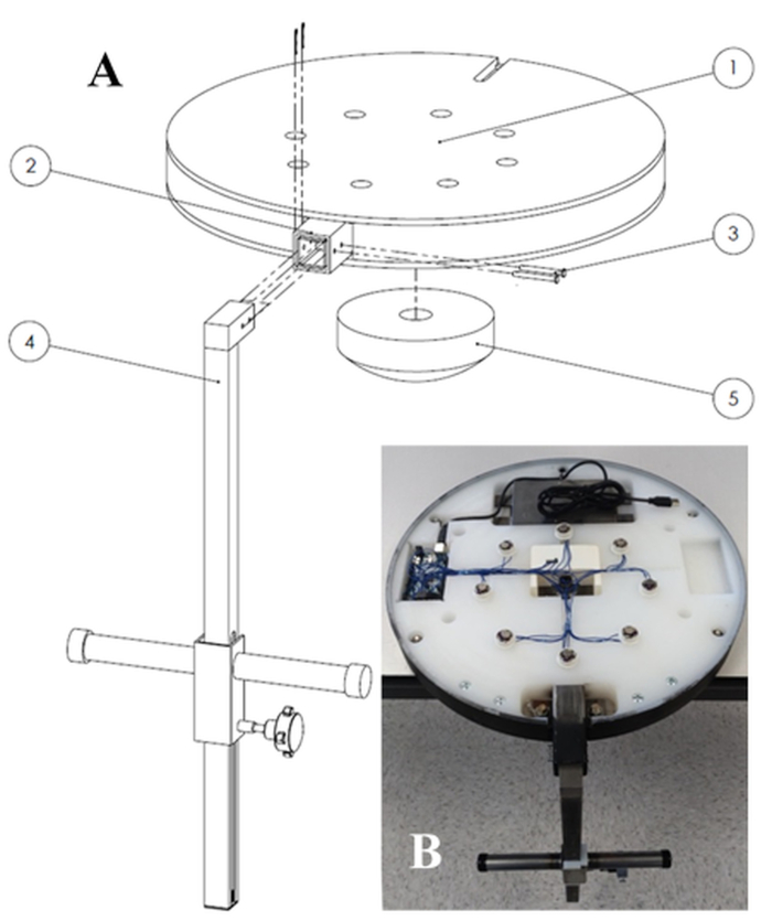
Figure 4: A vibrotactile feedback device for seated balance assessment and training. (A) Exploded view of the device's attachments. The components shown here are: (1) the base, chassis, and lid; (2) the steel extrusion for footrest attachment; (3) two clevis pins to secure the footrest; (4) the footrest attachment of adjustable height; and (5) one of five curved base modules. These components can be separated to facilitate transportation or storage. For detailed part dimensions, see Supplementary Files 1 (drawings) and 2 (3D solid models). (B) Top view photograph of the device. The lid has been removed to reveal electronic instrumentation, including: an inertial measurement unit housed by a custom-printed enclosure (center); a microcontroller board with universal serial bus connection (left); eight electronic vibrators held in custom-printed enclosures (mid-region); and a steel bar (top) to counterbalance the footrest This figure has been modified from Williams et al.18. Republished with permission of ASME, from "Design and Evaluation of an Instrumented Wobble Board for Assessing and Training Dynamic Seated Balance" in the Journal of Biomechanical Engineering, AD Williams, QA Boser, AS Kumawat, K Agarwal, H Rouhani, AH Vette, vol. 140, April 2018; permission conveyed through Copyright Clearance Center, Inc. Please click here to view a larger version of this figure.
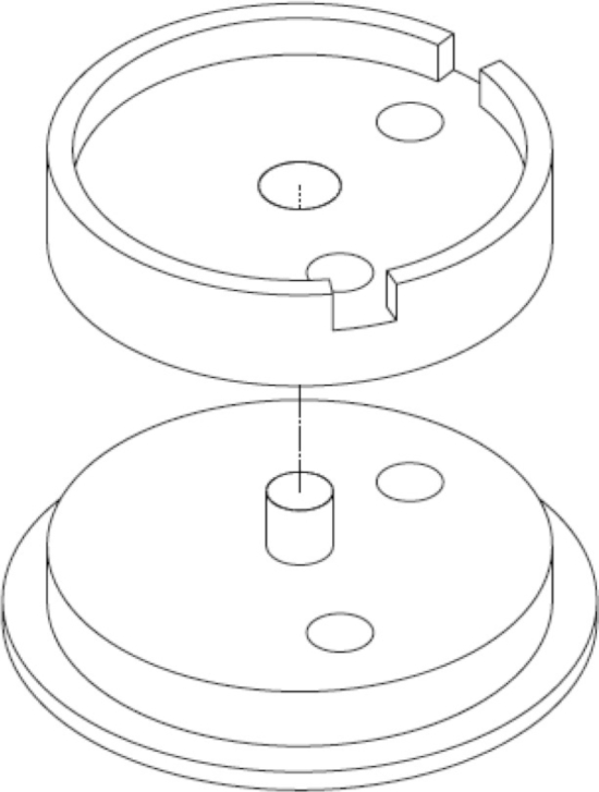
Figure 5: Two-part mounting enclosure for vibrating tactors. A 4 mm hole in the tactor enclosure (top) fitted loosely on a 3 mm locating pin in the mounting platform (bottom) to minimize vibration dampening. For detailed part dimensions, see Supplementary Files 1 (drawings) and 2 (3D solid models). Please click here to view a larger version of this figure.
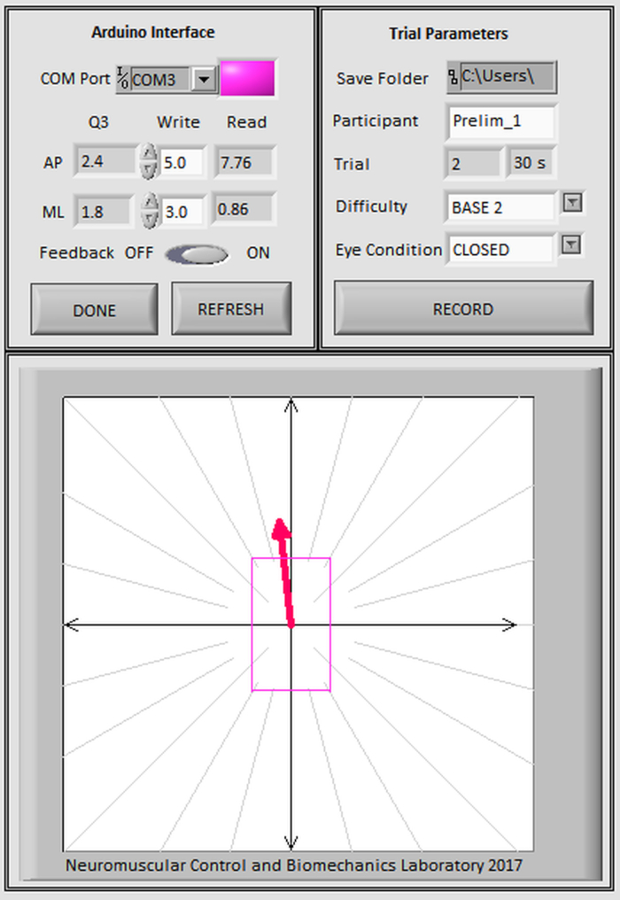
Figure 6: User interface. This user interface allows users to select vibrotactile feedback thresholds and acquire data. The length and direction of the vector on the graph are proportional to the kinematics of the device. The rectangle reflects the AP and ML thresholds for feedback. This figure has been modified from Williams et al.18. Republished with permission of ASME, from "Design and Evaluation of an Instrumented Wobble Board for Assessing and Training Dynamic Seated Balance" in the Journal of Biomechanical Engineering, AD Williams, QA Boser, AS Kumawat, K Agarwal, H Rouhani, AH Vette, vol. 140, April 2018; permission conveyed through Copyright Clearance Center, Inc. Please click here to view a larger version of this figure.
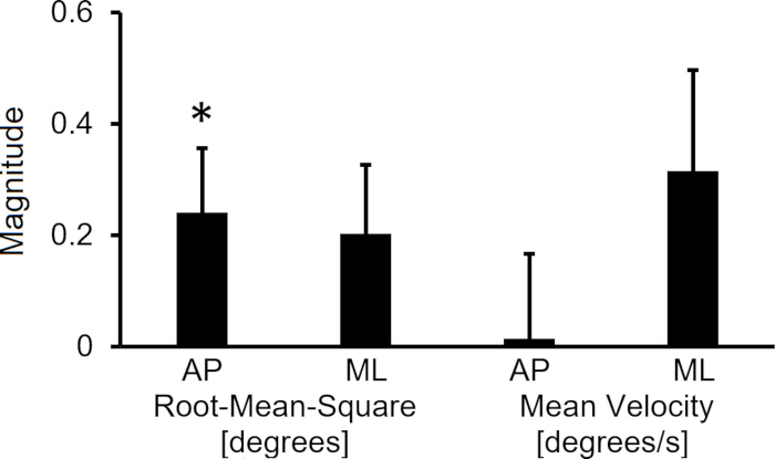
Figure 7: Results of task manipulation in time-domain. Change in time-domain posturographic measures when participants close their eyes and concurrently switch to a more stable base (mean and standard deviation; asterisk represents significant change according to F-test, α = 0.05). Please click here to view a larger version of this figure.
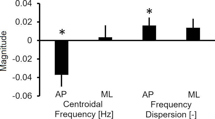
Figure 8: Results of task manipulation in frequency domain. Change in frequency-domain posturographic measures when participants close their eyes and concurrently switch to a more stable base (mean and standard deviation; asterisks represent significant change according to F-test, α = 0.05). Please click here to view a larger version of this figure.
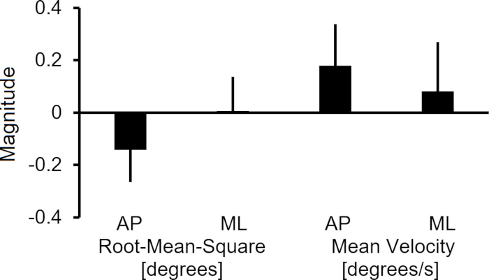
Figure 9: Results of vibrotactile feedback in time-domain. Change in time-domain posturographic measures when participants are provided with performance-based vibrotactile feedback (mean and standard deviation; no changes were statistically significant according to F-test, α = 0.05). Please click here to view a larger version of this figure.
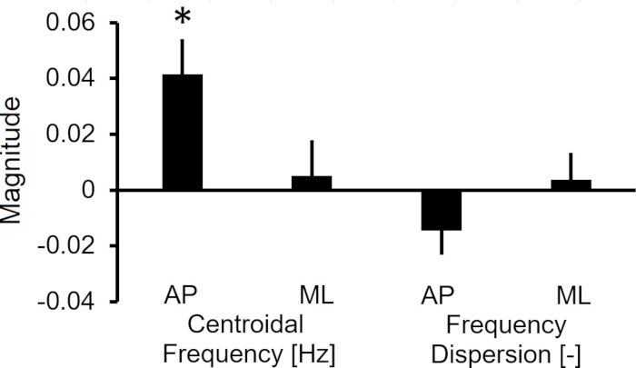
Figure 10: Results of vibrotactile feedback in frequency domain. Change in frequency-domain posturographic measures when participants are provided with performance-based vibrotactile feedback (mean and standard deviation; asterisk represents significant change according to F-test, α = 0.05). Please click here to view a larger version of this figure.
| Radius of curvature (cm) | ||
| Most stable | 25 | Less difficult to balance |
| 20 | ||
| 15 | ||
| 13 | ||
| Least stable | 11 | More difficult to balance |
Table 1: Geometrical properties of the interchangeable bases. The total height of each base module is 63 mm; thus, a base with a smaller radius of curvature, when attached to the device, is less stable than a base with a larger radius of curvature.
| Posturographic Measure | Tilt Direction | Experimental Condition | |||
| Eyes Open | Eyes Closed | ||||
| Very Unstable Surface | Mildly Unstable Surface | ||||
| Vibration | Vibration | Vibration | Vibration | ||
| Off | On | Off | On | ||
| Root-Mean-Square | Antero-Posterior | 1.60 | 1.62 | 2.01 | 1.70 |
| [degrees] | Medio-Lateral | 1.53 | 1.61 | 1.80 | 1.74 |
| Mean Velocity | Antero-Posterior | 2.75 | 3.01 | 2.85 | 2.94 |
| [degrees/s] | Medio-Lateral | 3.04 | 3.14 | 3.38 | 3.44 |
| Centroidal Frequency | Antero-Posterior | 0.418 | 0.449 | 0.370 | 0.423 |
| [Hz] | Medio-Lateral | 0.462 | 0.467 | 0.465 | 0.471 |
| Frequency Dispersion | Antero-Posterior | 0.659 | 0.654 | 0.685 | 0.661 |
| [-] | Medio-Lateral | 0.651 | 0.651 | 0.662 | 0.669 |
Table 2: Results by balance and feedback conditions. Summary measures derived from AP and ML tilts during unstable sitting trials. Support surface stability plus eye condition as well as vibration level are the manipulated variables. Average measures were calculated across all participants.
Supplementary File 1: Please click here to download this file.
Supplementary File 2: Please click here to download this file.
Supplementary File 3: Please click here to download this file.
Discussion
Methods for constructing a portable, instrumented, sitting device are presented. The device is portable and durable, building on previous studies of wobble chairs2,4 and vibrational feedback5,6,7 to make the benefits of these tools more powerful and accessible. Follow the assembly protocol in reverse to prepare the device for transportation or storage. The difficulty of the balance task can be modulated by attaching bases with different curvatures. The selection of task difficulty is critical; users should be destabilized to facilitate active training without risking injury.
Real-time observation and adjustment of the built-in instruments relies on serial communication between the microcontroller and the user interface; dysfunction of the device requires both software and hardware troubleshooting. Ensure that all hardware connections are secure. Monitor the serial output of the microcontroller for unexpected bytes. Probe the user interface program for errors. If a problem persists, consult an experienced mechatronics designer.
Balance proficiency is characterized by posturographic measures derived from kinematic observations of the sitting surface. Alternatively, observe the center of pressure exerted on a force plate, which correlates with the surface tilt angle2, but requires additional equipment. Posturographic measures have varying reliability between sessions2 and varying sensitivity to balance improvement or disorder19. The root-mean-square, mean velocity, centroidal frequency, and frequency dispersion are common posturographic measures that were observed to be linearly independent of each other. Consider modifying the signal analysis protocol to address particular assessment objectives.
The device delivers vibrotactile stimuli to the seat in accordance with balance task performance. The optimal configuration of haptic feedback control is the subject of continuous study and a critical step in this protocol, as certain feedback strategies may impair motor learning20. Existing vibrotactile feedback methods are proven to improve standing balance function and many other motor tasks6,7. Seat-embedded tactors make the vibrotactile feedback technique accessible for seated balance paradigms. Future applications may include sports training, spatial orientation training, virtual or augmented reality gaming, assessment of balance proficiency, research of balance disorders, and rehabilitation following skeletal, muscular, or neurological injury.
Disclosures
The authors have nothing to disclose.
Acknowledgements
The authors acknowledge the design efforts of the undergraduate students Animesh Singh Kumawat, Kshitij Agarwal, Quinn Boser, Benjamin Cheung, Caroline Collins, Sarah Lojczyc, Derek Schlenker, Katherine Schoepp, and Arthur Zielinski. This study was partially funded through a Discovery Grant from the Natural Sciences and Engineering Research Council of Canada (RGPIN-2014-04666).
Materials
| Name | Company | Catalog Number | Comments |
|---|---|---|---|
| Chassis | McMaster-Carr | 8657K421 | Moisture-Resistant LDPE Polyethylene Sheet 1-1/2" Thick, 24" X 24" |
| Lid | McMaster-Carr | 8657K414 | Moisture-Resistant LDPE Polyethylene Sheet 1/4" Thick, 24" X 24" |
| Base | McMaster-Carr | 8657K414 | Moisture-Resistant LDPE Polyethylene Sheet 1/4" Thick, 24" X 24" |
| Grip-Tape | McMaster-Carr | 6243T471 | Nonabrasive Antislip Tape, Textured, 6" Wide Strip, 2' Long, Black |
| Base Nut | McMaster-Carr | 90596A039 | Steel Round-Base Weld Nut, 5/8"-11 Thread Size |
| Weld Plate | McMaster-Carr | 1388K142 | Low-Carbon Steel Sheet 1/16" Thick, 3" X 3", Ground Finish |
| Threaded Rod | McMaster-Carr | 90322A170 | 3" 5/16"-18 Medium-Strength Alloy Steel Threaded Stud |
| Sleeve | McMaster-Carr | 8745K19 | Chemical-Resistant PVC (Type I) Rod 1-1/4" Diameter |
| Square Flange | McMaster-Carr | 8910K395 | Low Carbon Steel Bar, 1/8" Thick, 1" Wide |
| Hitch | McMaster-Carr | 4931T123 | Bolt-Together Framing Heavy-Duty Steel, 1-1/2" Square |
| Curved Base | McMaster-Carr | 8745K48 | PVC Rod, 6" Diameter |
| Hitch Insert | McMaster-Carr | 6535K313 | Bolt-Together Framing Heavy-Duty Steel, 1" Square |
| Extrusion | McMaster-Carr | 6545K7 | 1045 Cold Drawn Steel Square Bar Stock, 1' X 1" Wide, Unpolished |
| Clamp | Vlier | TH103A | Adjustable Torque Knob |
| Footrest | McMaster-Carr | 6582K431 | 4130 Steel Tubing, 1" X 1" Wide, 0.065" Wall Thickness, Unpolished Mill Finish |
| Counterwieght | McMaster-Carr | 8910K67 | Low-Carbon Steel Rectangular Bar 1-1/8" Thick, 4" Width |
| Clevis Pin | McMaster-Carr | 97245A616 | Zinc-Plated Steel Clevis Pin with Hairpin Cotter Pin, 3/16" Diameter, 1-9/16" Usable Length |
| Microprocessor | Arduino | MEGA 2560 | Microcontroller board with 54 digital I/O pins and USB connection |
| Inertial Measurement Unit | x-io Technologies Ltd. | x-IMU | Inertial Measurement Unit and Attitude Heading Reference System with enclosure |
| Vibrating Tactor | Precision Microdrives | DEV-11008 | Lilypad Vibe Board, available from SparkFun Electronics |
References
- Behm, D. G., Muehlbauer, T., Kibele, A., Granacher, U. Effects of Strength Training Using Unstable Surfaces on Strength, Power and Balance Performance Across the Lifespan: A Systematic Review and Meta-analysis. Sports Medicine. 45, 1645-1669 (2015).
- Larivière, C., Mecheri, H., Shahvarpour, A., Gagnon, D., Shirazi-Adl, A. Criterion validity and between-day reliability of an inertial-sensor-based trunk postural stability test during unstable sitting. Journal of Electromyography and Kinesiology. 23, 899-907 (2013).
- Paillard, T., Noé, F. Techniques and Methods for Testing the Postural Function in Healthy and Pathological Subjects. BioMed Research International. 2015, (2015).
- Williams, J., Bentman, S. An investigation into the reliability and variability of wobble board performance in a healthy population using the SMARTwobble instrumented wobble board. Physical Therapy in Sport. 25, 108(2017).
- Wall, C., Kentala, E. Effect of displacement, velocity, and combined vibrotactile tilt feedback on postural control of vestibulopathic subjects. Journal of Vestibular Research. 20, 61-69 (2010).
- Alahakone, A. U., Arosha Senanayake,, N, S. M. Vibrotactile feedback systems: Current trends in rehabilitation, sports and information display. IEEE/ASME International Conference on Advanced Intelligent Mechatronics. , 1148-1153 (2009).
- Shull, P. B., Damian, D. D. Haptic wearables as sensory replacement, sensory augmentation and trainer - a review. Journal of NeuroEngineering and Rehabilitation. 12, 12-59 (2015).
- Prieto, T. E., Myklebust, J. B., Hoffmann, R. G., Lovett, E. G., Myklebust, B. M. Measures of postural steadiness: Differences between healthy young and elderly adults. IEEE Transactions on Biomedical Engineering. 43, 956-966 (1996).
- Ribot-Ciscar, E., Vedel, J. P., Roll, J. P. Vibration sensitivity of slowly and rapidly adapting cutaneous mechanoreceptors in the human foot and leg. Neuroscience Letters. , 130-135 (1989).
- Churchill, E., McConville, J. T. Sampling and Data Gathering Strategies for Future USAF Anthropometry. , (1976).
- Lee, H., Granata, K. P. Process stationarity and reliability of trunk postural stability. Clinical Biomechanics. 23, 735-742 (2008).
- Silfies, S. P., Cholewicki, J., Radebold, A. The effects of visual input on postural control of the lumbar spine in unstable sitting. Human Movement Science. 22, 237-252 (2003).
- Loughlin, P., Mahboobin, A., Furman, J. Designing vibrotactile balance feedback for desired body sway reductions. Annual International Conference of the IEEE Engineering in Medicine and Biology Society. , 1310-1313 (2011).
- Goodworth, A. D., Wall, C., Peterka, R. J. Influence of feedback parameters on performance of a vibrotactile balance prosthesis. IEEE Transactions on Neural Systems and Rehabilitation Engineering. 17, 397-408 (2009).
- Marchal-Crespo, L., Reinkensmeyer, D. J. Review of control strategies for robotic movement training after neurologic injury. Journal of NeuroEngineering and Rehabilitation. 6, 20-35 (2009).
- Lee, B., Kim, J., Chen, S., Sienko, K. H. Cell phone based balance trainer. Journal of NeuroEngineering and Rehabilitation. 9, 1-14 (2012).
- Sienko, K. H., Balkwill, M. D., Wall, C. Biofeedback improves postural control recovery from multi-axis discrete perturbations. Journal of NeuroEngineering and Rehabilitation. 9, 53-64 (2012).
- Williams, A., et al. Design and Evaluation of an Instrumented Wobble Board for Assessing and Training Dynamic Seated Balance. Journal of Biomechanical Engineering. 140, 1-10 (2017).
- van Dieën, J. H., Koppes, L. L. J., Twisk, J. W. R. Postural sway parameters in seated balancing; their reliability and relationship with balancing performance. Gait Posture. 31, 42-46 (2010).
- Sigrist, R., Rauter, G., Riener, R., Wolf, P. Augmented visual, auditory, haptic, and multimodal feedback in motor learning: A review. Psychonomic Bulletin and Review. 20, 21-53 (2013).
Reprints and Permissions
