Key procedures to optimize the sealing process and achieve real-time monitoring of the metal-to-glass seal (MTGS) structure are described in detail. The embedded fiber Bragg grating (FBG) sensor is designed to achieve online monitoring of temperature and high-level residual stress in the MTGS with simultaneous environmental pressure monitoring.
Method Article
Optimized Sealing Process and Real-Time Monitoring of Glass-to-Metal Seal Structures
1Institute of Nuclear and New Energy Technology, Key Laboratory of Advanced Reactor Engineering and Safety of Ministry of Education, Collaborative Innovation Center for Advanced Nuclear Energy Technology, Tsinghua University, 2Institute of Nuclear and New Energy Technology, Beijing Key Laboratory of Fine Ceramics, Tsinghua University
Opens in a new tab
In This Article
Summary
Loading...
$$\rightleftharpoonup{xx}$$
$$\longleftharp{xx}$$,
$$\longrightharp{xx}$$,
Abstract
Loading...
$$\rightleftharpoonup{xx}$$
$$\longleftharp{xx}$$,
$$\longrightharp{xx}$$,
Residual stress is an essential factor to keeping the hermeticity and robustness of a glass-to-metal seal structure. The purpose of this report is to demonstrate a novel protocol to characterize and measure residual stress in a glass-to-metal seal structure without destroying the insulation and hermeticity of sealing materials. In this research, a femto-laser inscribed fiber Bragg grating sensor is used. The glass-to-metal seal structure that is measured consists of a metal shell, sealing glass, and Kovar conductor. To make the measurements worthwhile, the specific heat treatment of metal-to-glass seal (MTGS) structure is explored to obtain the model with best hermeticity. Then, the FBG sensor is embedded into the path of sealing glass and becomes well-fused with the glass as the temperature cools to RT. The Bragg wavelength of FBG shifts with the residual stress generated in sealing the glass. To calculate the residual stress, the relationship between Bragg wavelength shift and strain is applied, and the finite element method is also used to make the results reliable. The online monitoring experiments of residual stress in sealing glass are carried out at different loads, such as high temperature and high pressure, to broaden functions of this protocol in harsh environments.
Introduction
Loading...
$$\rightleftharpoonup{xx}$$
$$\longleftharp{xx}$$,
$$\longrightharp{xx}$$,
Metal-to-glass sealing is a sophisticated technology that combines interdisciplinary knowledge (i.e., mechanics, materials, and electrical engineering) and is widely applied in aerospace1, nuclear energy2, and biomedical applications3. It has unique advantages such as higher temperature and pressure endurance compared with organic material sealing structures. According to the difference of coefficient of thermal expansion (CTE), MTGS can be divided into two types: matched seal and mismatched seal4. As for the matched seal, the CTE of metal (αmetal) and sealing glass (αglass) are nearly the same to reduce the thermal stress in sealing materials. However, to keep good hermeticity and mechanical robustness of the seal structure in harsh environments (i.e., high temperature and high pressure), the mismatched seal displays better performance than the matched seal. Due to the difference between αmetal and αglass, the residual stress generates in sealing glass after the annealing process of MTGS structure. If the residual stress is too large (even exceeding the threshold value), the sealing glass displays small defects, such as cracks. If the residual stress is too small, the sealing glass loses its hermeticity. As a result, the value of residual stress is an important measurement.
Analysis of residual stress in MTGS structures has aroused research interests of many groups around the world. The numerical model of axial and radial stress was built based on thin shell theory5. The finite element method was applied to obtain the global stress distribution of an MTGS structure after the annealing process, which was consistent with experimental results6,7. However, because of limitations involving small size and electromagnetic interference, many advanced sensors are not suitable for these circumstances. The indentation crack length method was reported to measure the residual stress in the sealing material of MTG; however, this method was destructive and could not achieve real-time online monitoring of stress changes in glass.
Fiber Bragg grating (FBG) sensors are small in size (~100 µm) and resistant to electromagnetic interference and harsh environments8. In addition, the components of the fiber are similar to those of sealing glass (SiO2), so FBG sensors have no effects on the hermeticity and insulation of the sealing material. FBG sensors have been applied to the residual stress measurement in composite structures9,10,11, and results showed that it displayed good measuring precision and signal response. Simultaneous temperature and stress measurements may be achieved by fiber Bragg grating arrays on one optical fiber12,13.
A novel protocol based on an FBG sensor is demonstrated in this study. The appropriate preparation for the special MTGS structure has been explored by adjusting the maximum heat temperature to ensure the good hermeticity of the MTGS structure. The FBG sensor is embedded in the prepared path of sealing glass to fuse the FBG and glass together after the heat treatment. Then, the residual stress can be obtained by the Bragg wavelength shift of the FBG. The MTGS structure with the FBG sensor is placed under high temperature and high pressure environments to achieve online monitoring of residual stress under changing loads. In this study, the detailed steps to produce an MTS structure with a FBG sensor are outlined. The results show the feasibility of this novel protocol and establish the foundation for the failure diagnosis of an MTGS structure.
Access restricted. Please log in or start a trial to view this content.
Protocol
Loading...
$$\rightleftharpoonup{xx}$$
$$\longleftharp{xx}$$,
$$\longrightharp{xx}$$,
1. Production of MTGS structure with good hermeticity
NOTE: The procedures for MTGS structure include the preparations for components of the combined structure, the heat treatment process, and examinations for the performance of MTGS samples. The complete MTGS structure consists of a steel shell, Kovar conductor, and sealing glass. See the diagram and dimensions shown in Figure 1 and Table 1, respectively.
- Pour the granulated glass powder (~1.1 g) into the mold, then place the mold onto the press machine to process the granulated glass as shown in Figure 2a,b.
- Switch on the press machine (push the red button) to compact the granulated glass into the glass cylinder as shown in Figure 2c,d.
NOTE: The density control of glass cylinder is important for the performance of the MTGS structure, because too many pores in the glass cylinder will lead to failure of the hermeticity of MTGS structure. - Place the glass cylinder into the heating furnace to be sintered (see Figure 3).
- The sintered glass cylinder, steel shell, and Kovar conductor are manufactured with a special graphite gasket, as shown in Figure 4. Place this model onto the quartz septum in the heating furnace using a claw for heat treatment (see Figure 4). Keep the cooling rate as 0.5 °C/min to avoid breaking of the optical fiber.
- Use visual inspection to identify the surface topography of sealing glass after retrieving the model from the heating furnace.
- Use the high pressure pipeline to examine the hermeticity of MTGS model. Install the model onto the pipeline by the card sleeve type joint. Slowly change the pressure from 1 MPa to 8 MPa, holding each pressure for 24 h.
- Use the scanning electron microscope (SEM) to identify the microscopic interface between sealing glass and metal parts as shown in Figure 5. Use 15 kV and 500x magnification to observe the interface clearly.
NOTE: From the macrography examination and SEM results, the standard maximum heating temperature is set as 450 °C to obtain the MTGS model with good hermeticity. The standard heating treatment is defined as follows: increase the temperature from (room temperature) RT to 450 °C in increments of 5 °C/min, then drop the temperature to RT as 0.5 °C/min.
2. Residual stress measurement in sealing glass
NOTE: The FBG sensor is designed as an appropriate method to measure the stress in the MTGS. The grating length of the FBG sensor is 5 mm to match the height of the glass (5 mm) well.
- Compact the granulated glass powder into the glass cylinder as described in steps 1.1–1.2.
NOTE: The height of glass cylinder is important, because if the cylinder is too high (>6 mm), it will be difficult to make a through path for the FBG sensor without destroying the glass material. - Drill the glass cylinder using drill speed of 5,000 rpm to produce three equally spaced through-holes to prepare paths for optical fiber sensors (diameter 0.45 mm). Sinter the glass cylinder with holes using the same heat treatment as shown in Figure 4.
- Manufacture the MTGS model as described in step 1.4. Then, put the fiber through the path in sealing glass and position the grating region of the FBG exactly within the glass.
NOTE: Because the flow in the vertical furnace can blow up the grating region, which leads to the mismatching of FBG and glass, the tail of optical fiber must be hung with a small nail to keep the position of FBG accurate. - Fuse the head of optical fiber with a FC connector by the fusion splicers. Then, match the FC connector with the OPM-T400, which is an interrogator to demodulate the wavelength data and spectrum of FBG. The OPM-T400 is connected to a computer, and the supporting software on the computer can obtain experimental data.
- Process the whole model in a furnace by the standard heat treatment obtained previously. Raise the temperature from RT to 450 °C as 5 °C/min, then drop the temperature to RT in increments of 0.5 °C/min. The grating region will become fused with the sealing glass as it is heated to melt. When the temperature cools down to RT, the glass will solidify and the FBG sensor will become well-fused with the sealing material.
- Record the real-time Bragg wavelength data using the software (shown in Figure 6). The only factor inducing changes of wavelength and spectrum is the residual stress generated in sealing glass, because the temperature before and after this step is both RT.
NOTE: The residual stress can be calculated through the strain-wavelength relationship of FBG14 and Hook’s law, as shown below.
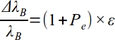

Where: the ΔλB is the Bragg wavelength shift induced by the residual stress, λB is the initial wavelength of FBG, Pe is the strain-optic coefficient, ε is the residual strain in the glass, E is the Young’s modulus of sealing glass, and σ is the residual stress in the glass.
3. Preventing the failure of MTGS structure under high temperature
NOTE: When working at a high temperature, the hermeticity of the MTGS structure will be affected, because the thermal expansion of steel shell leads to the decrease of residual stress in sealing glass. Thus, it is possible this protocol can prevent the failure of hermeticity due to the online monitoring of residual stress change in sealing glass.
- Manufacture the MTGS model as done in step 1.4. The type of FBG to monitor temperature and stress simultaneously is the fiber Bragg grating array sensor, including two grating regions on one fiber, with a 10 mm distance between these two sensors.
NOTE: These two grating are defined as FBG-1 and FBG-2. The initial Bragg wavelengths of FBG-1 and FBG-2 are 1545 nm and 1550 nm, respectively. - Place FBG-1 into the sintered glass cylinder to monitor the stress and temperature. Place FBG-2 outside the glass to monitor the temperature only, as shown in Figure 7a,b. In this way, FBG-1 is affected by both temperature and residual stress change, and FBG-2 is only affected by temperature of sealing glass.
- Place the MTGS model with optical fiber in the furnace as described in steps 2.2–2.3. Use the standard heat treatment to process the MTGS model with an embedded FBG sensor.
- Impose temperatures of 100 °C, 200 °C, 300 °C, and 400 °C onto the model and hold each temperature for 100 min.
NOTE: FBG-1 monitors the stress and temperature simultaneously expressed as the Bragg wavelength shift ΔλB-1, and FBG-2 monitors the temperature change by ΔλB-2 as shown in Figure 8a,b. The relationships between Bragg wavelength shift and measured parameters are shown as follows:

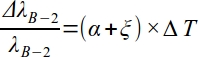
Where: ξ is thermo-optic coefficient, α is thermal expansion coefficient of optical fiber, and ΔT is temperature change before and after the experiment. The ΔλB-3 induced by residual stress can be separated through subtracting ΔλB-1 from ΔλB-2 (see Figure 8c). This is the demodulation method for simultaneous temperature and stress monitoring of sealing glass at high temperatures.
4. Monitoring high pressure
NOTE: The pressure loads on the MTGS structure will have effects on the residual stress in sealing glass, so the MTGS model with the embedded FBG sensor is a potential method to monitor the high pressure change.
- Prepare the same MTGS model with the FBG sensor as described in step 2.2–2.3. After the FBG is well-fused with MTGS model, use the claw to take the model out of the furnace.
- Manufacture the MTGS model with the FBG sensor onto a high pressure helium pipeline by the bite type tube fittings as shown in Figure 9. Adjust the pressure from 1 MPa to 7 MPa by pressure reducing the valve to impose changing pressure loads on the sealing structure.
- The Bragg wavelength shift ΔλB is recorded as shown in Figure 10. At the same time, the related residual stress change can be calculated using Equation 1 and Equation 2.
5. Theoretical analysis of MTGS structure
- Use the modeling software to build the 3D model for MTGS structure, and the dimensions are taken from Table 1 to keep the experimental model and theoretical model consistent.
- Import the 3D model into the finite element analysis software. Assign mechanical properties to the steel shell, sealing glass and Kovar conductor, as shown in Table 2.
- The grid type of the whole model is Hex shape (see Figure 11). The mesh method of the sealing glass and steel shell are sweep, and the Kovar conductor is meshed by structured method. Refine the mesh of sealing glass to guarantee the accuracy of theoretical results. The elements number of Kovar conductor, sealing glass and steel shell are 143700, 20350, and 13400, respectively.
- Set the initial increment, minimum increment, and maximum increment of the static analysis step as 0.01, 1.00 x 10⁻⁸ and 1.00 x 10⁻², respectively.
- Ensure that the interfaces between the sealing glass and metal parts are bounded. First, impose the changing temperature load (from 370 °C to 20 °C) to simulate the solidification progress of the MTGS model. The stress distribution after this process is shown in Figure 12.
- Impose different temperatures (from 100 °C to 400 °C) onto the whole model to simulate the online monitoring experiments under thermal loads. Under the other circumstance, changing pressure loads (from 1 MPa to 7 MPa) are imposed on the sealing glass to simulate the online monitoring under high pressure. The boundary conditions are shown in Figure 13.
- The numerical results of stress and strain distribution of the whole model are obtained from the destination file shown in Figure 14. Extract the analysis path in the sealing glass shown in Figure 13, of which the position is the monitoring path for FBG sensors in Figure 6a to provide comparison with the measuring results by FBG.
Access restricted. Please log in or start a trial to view this content.
Results
Loading...
$$\rightleftharpoonup{xx}$$
$$\longleftharp{xx}$$,
$$\longrightharp{xx}$$,
From the results of Figure 5, the standard heat treatment to produce the MTGS models with high pressure endurance is explored, and the models can satisfy the examinations (i.e., light transmissions, pressure endurance, SEM, etc.). Thus, the produced MTGS structure can be applied to keep hermeticity in harsh environments.
The FBG can be well-fused with MTGS structure, and the residual strain in sealing glass will be reflected by Bragg wavelength shift after the hea...
Access restricted. Please log in or start a trial to view this content.
Discussion
Loading...
$$\rightleftharpoonup{xx}$$
$$\longleftharp{xx}$$,
$$\longrightharp{xx}$$,
The critical steps for the stress measuring of sealing material of MTGS structure at high temperature and high pressure include 1) manufacturing of the MTGS models with the FBG sensor, of which the grating region is located at the middle of sealing glass; 2) heating of the whole model using a standard heat treatment process, and after the model cools to RT, the FBG sensor will becomes well-fused with MTGS model, and the residual stress can be measured by Bragg wavelength shift; 3) placing of the complete model into the f...
Access restricted. Please log in or start a trial to view this content.
Disclosures
Loading...
$$\rightleftharpoonup{xx}$$
$$\longleftharp{xx}$$,
$$\longrightharp{xx}$$,
The authors have nothing to disclose.
Acknowledgements
Loading...
$$\rightleftharpoonup{xx}$$
$$\longleftharp{xx}$$,
$$\longrightharp{xx}$$,
This work has been supported by the National S&T Major Project of China (ZX069).
Access restricted. Please log in or start a trial to view this content.
Materials
| Name | Company | Catalog Number | Comments |
|---|---|---|---|
| ABAQUS | Dassault SIMULA | ABAQUS6.14-5 | The software to carry out numerical simulation. |
| Fiber Bragg grating sensors | Femto Fiber Tec | FFT.FBG.S.00.02 Single | apodized FBG |
| Fusion splicer | Furukawa Information Technologies and Telecommunications | S123M12 | FITEL's line of fusion splicers provides an excellent solution for both field and factory splicing applications? |
| Glass powder | Shenzhen Sialom Advanced Materials Co.,Ltd | LC-1 | A kind of low melting-point glass powder (380?). |
| Graphite mold | Machining workshop of Tsinghua University | Graphite | The mold to locate each part of the metal-to-glass structure. |
| Heating furnace | Tianjin Zhonghuan Electric Furnace Technology Co., Ltd | SK-G08123-L | vertical tubular furnace |
| Kovar conductor | Shenzhen Thaistone Technology Co., Ltd | 4J29 | A common material used for the electrical penetration in the metal-to-glass seal structure |
| Optical interrogator | Wuhan Gaussian Optics CO.,LTD | OPM-T400 | FBG spectrum analysis modules |
| Pro/Engineer | Parametric Technology Corporation | PROE5.0 | The software to establish the 3D geometry. |
| Steel shell | Beijing Xiongchuan Technology Co., Ltd | 316 stainless steel | A kind of austenitic stainless steel |
References
Loading...
$$\rightleftharpoonup{xx}$$
$$\longleftharp{xx}$$,
$$\longrightharp{xx}$$,
- Alves, F. J., Baptista, A. M., Marques, A. T. Metal and ceramic matrix composites in aerospace engineering. Advanced Composite Materials for Aerospace Engineering. , 59-99 (2016).
- Dai, S., et al. Sealing Glass-Ceramics with Near Linear Thermal Strain, Part I: Process Development and Phase Identification. Journal of the American Ceramic Society. 99 (11), 3719-3725 (2016).
- Karmakar, B. Glasses and glass-ceramics for biomedical applications. Functional Glasses and Glass-Ceramics. , 253-280 (2017).
- Shekoofa, O., et al. Analysis of residual stress for mismatch metal–glass seals in solar evacuated tubes. Solar Energy Materials and Solar Cells. 128, 421-426 (2014).
- Lei, D., Wang, Z., Li, J. The calculation and analysis of glass-to-metal sealing stress in solar absorber tube. Renewable Energy. 35 (2), 405-411 (2010).
- Lei, D., Wang, Z., Li, J. The analysis of residual stress in glass-to-metal seals for solar receiver tube. Materials & Design. 31, 1813-1820 (2010).
- Dai, S., et al. Sealing glass-ceramics with near-linear thermal strain, part III: Stress modeling of strain and strain rate matched glass-ceramic to metal seals. Journal of the American Ceramic Society. 100 (8), 3652-3661 (2017).
- Hill, K. O., Meltz, G. Fiber Bragg grating technology fundamentals and overview. Journal of Lightwave Technology. 15 (8), 1263-1276 (1997).
- Prussak, P., et al. Evaluation of residual stress development in FRP-metal hybrids using fiber Bragg grating sensors. Production Engineering - Research and Development. 12, 259-267 (2018).
- Hu, H., et al. Investigation of non-uniform gelation effects on residual stresses of thick laminates based on tailed FBG sensor. Composite Structures. 202, 1361-1372 (2018).
- Colpo, F., Humbert, L., Botsis, J. Characterisation of residual stresses in a single fibre composite with FBG sensor. Composites Science & Technology. 67 (9), 1830-1841 (2007).
- Jin, L., et al. An embedded FBG sensor for simultaneous measurement of stress and temperature. IEEE Photonics Technology Letters. 18 (1), 154-156 (2005).
- Sampath, U., et al. Polymer-coated FBG sensor for simultaneous temperature and strain monitoring in composite materials under cryogenic conditions. Applied Optics. 57 (3), 492-497 (2018).
- Kersey, A., et al. Fiber grating sensors. Journal of Lightwave Technology. 15 (8), 1442-1463 (1997).
- Mihailov, S. J. Fiber Bragg Grating Sensors for Harsh Environments. Sensors. 12 (12), 1898-1918 (2012).
- Morey, W. W., Meltz, G., Weiss, J. M. Recent advances in fiber-grating sensors for utility industry applications. Proceedings of SPIE - The International Society for Optical Engineering. , 90-98 (1996).
- Jin, X., Yuan, S., Chen, J. On crack propagation monitoring by using reflection spectra of AFBG and UFBG sensors. Sensors and Actuators A: Physical. 285, 491-500 (2019).
- Kakei, A., et al. Evaluation of delamination crack tip in woven fibre glass reinforced polymer composite using FBG sensor spectra and thermo-elastic response. Measurement. 122, 178-185 (2018).
- Zhang, W., et al. The Analysis of FBG Central Wavelength Variation with Crack Propagation Based on a Self-Adaptive Multi-Peak Detection Algorithm. Sensors. 19 (5), 1056(2019).
Access restricted. Please log in or start a trial to view this content.
Reprints and Permissions
Request permission to reuse the text or figures of this JoVE article
Request Permission