This article presents an experimental/analytic framework to study human postural control. The protocol provides step-by-step procedures for performing standing experiments, measuring body kinematics and kinetics signals, and analyzing the results to provide insight into the mechanisms underlying human postural control.
A subscription to JoVE is required to view this content. Sign in or start your free trial.
Method Article
Experimental Methods to Study Human Postural Control
In This Article
Summary
Abstract
Many components of the nervous and musculoskeletal systems act in concert to achieve the stable, upright human posture. Controlled experiments accompanied by appropriate mathematical methods are needed to understand the role of the different sub-systems involved in human postural control. This article describes a protocol for performing perturbed standing experiments, acquiring experimental data, and carrying out the subsequent mathematical analysis, with the aim of understanding the role of musculoskeletal system and central control in human upright posture. The results generated by these methods are important, because they provide insight into the healthy balance control, form the basis for understanding the etiology of impaired balance in patients and the elderly, and aid in the design of interventions to improve postural control and stability. These methods can be used to study the role of somatosensory system, intrinsic stiffness of ankle joint, and visual system in postural control, and may also be extended to investigate the role of vestibular system. The methods are to be used in the case of an ankle strategy, where the body moves primarily about the ankle joint and is considered a single-link inverted pendulum.
Introduction
Human postural control is realized through complex interactions between the central nervous and musculoskeletal systems1. The human body in standing is inherently unstable, subject to a variety of internal (e.g., respiration, heartbeat) and external (e.g., gravity) perturbations. Stability is achieved by a distributed controller with central, reflex, and intrinsic components (Figure 1).
Postural control is achieved by: an active controller, mediated by the central nervous system (CNS) and spinal cord, which changes muscle activation; and an intrinsic stiffness controller that resists joint movement with no change in muscle activation (Figure 1). The central controller uses sensory information to generate descending commands that produce corrective muscle forces to stabilize the body. Sensory information is transduced by the visual, vestibular, and somatosensory systems. Specifically, the somatosensory system generates information regarding the support surface and joint angles; vision provides information regarding the environment; and the vestibular system generates information regarding the head angular velocity, linear acceleration, and orientation with respect to gravity. The central, closed-loop controller operates with long delays that may be destabilizing2. The second element of the active controller is reflex stiffness, which generates muscle activity with short latency and produces torques resisting joint movement.
There is a latency associated with both components of active controller; consequently, joint intrinsic stiffness, which acts with no delay, plays an important role in postural control3. Intrinsic stiffness is generated by passive visco-elastic properties of contracting muscles, soft tissues and inertial properties of the limbs, which generates resistive torques instantaneously in response to any joint movement4. The role of the joint stiffness (intrinsic and reflex stiffness) in postural control is not clearly understood, since it changes with operating conditions, defined by muscle activation4,5,6 and joint position4,7,8, both of which change with the body sway, inherent to standing.
Identifying the roles of the central controller and joint stiffness in postural control is important, as it provides the basis for: diagnosing the etiology of balance impairments; the design of targeted interventions for patients; assessment of the risk of falls; the development of strategies for fall prevention in the elderly; and the design of assistive devices such as orthotics and prosthetics. However, it is difficult, because the different sub-systems act together and only the overall resulting body kinematics, joint torques, and muscle electromyography can be measured.
Therefore, it is essential to develop experimental and analytical methods that use the measurable postural variables to evaluate each subsystem’s contribution. A technical difficulty is that the measurement of postural variables is done in closed-loop. As a result, the inputs and outputs (cause and effect) are interrelated. Consequently, it is necessary to: a) apply external perturbations (as inputs) to evoke postural reactions in responses (as outputs), and b) employ specialized mathematical methods to identify system models and disentangle cause and effect9.
The present article focuses on postural control when an ankle strategy is used, that is, when the movements occur primarily about the ankle joint. In this condition, upper body and lower limbs move together, consequently, the body can be modeled as a single-link inverted pendulum in sagittal plane10. The ankle strategy is used when the support surface is firm and the perturbations are small1,11.
A standing apparatus capable of applying appropriate mechanical (proprioceptive) and visual sensory perturbations and recording the body kinematics, kinetics, and muscle activities has been developed in our laboratory12. The device provides the experimental environment needed to study the role of ankle stiffness, central control mechanisms, and their interactions by generating postural responses using visual or/and somatosensory stimuli. It is also possible to extend the device to study the role of vestibular system by the application of direct electrical stimulation to the mastoid processes, that can generate a sensation of head velocity and evoke postural responses12,13.
Others have also developed similar devices to study human postural control, where linear piezo electric actuators11, rotary electrical motors14,15, and linear electrical motors16,17,18 were used to apply mechanical perturbations to ankle in standing. More complex devices also have been developed to study multi-segment postural control, where it is possible to apply multiple perturbations to ankle and hip joints simultaneously19,20.
Standing apparatus
Two servo-controlled electrohydraulic rotary actuators move two pedals to apply controlled perturbations of ankle position. The actuators can generate large torques (>500 Nm) needed for postural control; this is especially important in cases such as forward lean, where the body’s center of mass is far (anterior) from ankle axis of rotation, resulting in large values of ankle torque for postural control.
Each rotary actuator is controlled by a separate proportional servo valve, using pedal position feedback, measured by a high-performance potentiometer on the actuator shaft (Table of Materials). The controller is implemented using a MATLAB-based xPC real-time, digital signal processing system. The actuator/servo-valve together have a bandwidth of more than 40 Hz, much larger than bandwidth of the overall postural control system, ankle joint stiffness, and the central controller21.
Virtual reality device and environment
A virtual reality (VR) headset (Table of Materials) is used to perturb the vision. The headset contains an LCD screen (dual AMOLED 3.6’’ screen with a resolution of 1080 x 1200 pixels per eye) that provides the user with a stereoscopic view of the media sent to the device, offering three-dimensional depth perception. The refresh rate is 90 Hz, sufficient to provide a solid virtual sense to the users22. The field of view of the screen is 110°, enough to generate visual perturbations similar to real world situations.
The headset tracks the rotation of the user’s head and alters the virtual view accordingly so that the user is fully immersed in the virtual environment; therefore, it can provide the normal visual feedback; and it can also perturb vision by rotating the visual field in sagittal plane.
Kinetic measurements
Vertical reaction force is measured by four load cells, sandwiched between two plates beneath the foot (Table of Materials). Ankle torque is measured directly by torque transducers with a capacity of 565 Nm and a torsional stiffness of 104 kNm/rad; it also can be measured indirectly from the vertical forces transduced by the load cells, using their distances to ankle axis of rotation23, assuming that horizontal forces applied to the feet in standing are small2,24. Center of pressure (COP) is measured in sagittal plane by dividing the ankle torque by the total vertical force, measured by the load cells23.
Kinematic measurements
Foot angle is the same as pedal angle, because when an ankle strategy is used, the subject’s foot moves with the pedal. Shank angle with respect to the vertical is obtained indirectly from the linear displacement of the shank, measured by a laser range finder (Table of Materials) with a resolution of 50 μm and bandwidth of 750 Hz25. Ankle angle is the sum of the foot and shank angles. Body angle with respect to the vertical is obtained indirectly from the linear displacement of the mid-point between the left and right posterior superior iliac spines (PSIS), measured using a laser range finder (Table of Materials) with a resolution of 100 μm and bandwidth of 750 Hz23. Head position and rotation are measured with respect to the global coordinate system of the VR environment by the VR system base stations that emit timed infrared (IR) pulses at 60 pulses per second that are picked up by the headset IR sensors with sub-millimeter precision.
Data acquisition
All signals are filtered with an anti-aliasing filter with a corner frequency of 486.3 and then sampled at 1000 Hz with high performance 24-bit/8-channel, simultaneous-sampling, dynamic signal acquisition cards (Table of Materials) with a dynamic range of 20 V.
Safety mechanisms
Six safety mechanisms have been incorporated into the standing apparatus to prevent injuries to subjects; the pedals are controlled separately and never interfere with each other. (1) The actuator shaft has a cam, which mechanically activates a valve that disconnects hydraulic pressure if the shaft rotation exceeds ± 20° from its horizontal position. (2) Two adjustable mechanical stops limit the range of motion of the actuator; these are set to each subject’s range of motion prior to each experiment. (3) Both the subject and the experimenter hold a panic button; pressing the button disconnects hydraulic power from the actuators and causes them to become loose, so they can be moved manually. (4) Handrails located at either side of the subject are available to provide support in case of instability. (5) The subject wears a full body harness (Table of Materials), attached to rigid crossbars in the ceiling to support them in case of a fall. The harness is slack and does not interfere with normal standing, unless the subject becomes unstable, where the harness prevents the subject from falling. In the case of fall, the pedal movements will be stopped manually either by the subject, using the panic button or by the experimenter. (6) The servo-valves stop the rotation of the actuators using fail-safe mechanisms in case of electrical supply interruption.
Access restricted. Please log in or start a trial to view this content.
Protocol
All experimental methods have been approved by the McGill University Research Ethics Board and subjects sign informed consents before participating.
1. Experiments
NOTE: Each experiment involves the following steps.
- Pre-test
- Prepare a definite outline of all trials to be performed and make a checklist for data collection.
- Provide the subject with a consent form with all the necessary information, ask them to read it thoroughly, answer any questions, and then have them sign the form.
- Record the subject’s weight, height, and age.
- Subject preparation
- Electromyography measurement
- Use single differential electrodes (Table of Materials) with an inter-electrode distance of 1 cm for the measurement of electromyography (EMG) of ankle muscles.
- Use an amplifier (Table of Materials) with an overall gain of 1000 and a bandwidth of 20−2000 Hz.
- To ensure a high signal to noise ratio (SNR) and minimal cross-talk, locate and mark the electrode attachment areas according to guidelines provided by the Seniam project26, as below: (1) for the medial gastrocnemius (MG), the most prominent bulge of the muscle; (2) for the lateral gastrocnemius (LG), 1/3 of the line between the head of the fibula and the heel; (3) for soleus (SOL), 2/3 of the line between the medial condyles of the femur and the medial malleolus; (4) for tibialis anterior (TA), 1/3 of the line between the tip of the fibula and the tip of the medial malleolus.
- Shave the marked areas with a razor and clean the skin with alcohol. Allow the skin to dry thoroughly.
- Shave a bony area on the patella for the reference electrode, and clean with alcohol.
- Have the subject lie in a relaxed supine position.
- Place the reference electrode on the shaved area of the patella.
- Attach the electrodes one by one to the shaved areas of the muscles, using double sided tape, taking care to ensure that the electrodes are fixed to the skin securely.
- After placing each electrode, ask the subject to perform a plantarflexing/dorsiflexing contraction against resistance and examine the waveforms on an oscilloscope to ensure that the EMG signal has a high SNR. If the signal SNR is poor, move the electrodes until a location with a high SNR is found.
- Make sure that the subject’s movements are not hindered by the EMG cables.
- Kinematic measurements
- Attach a reflective marker to the shank with a strap, to be used for shank angle measurement.
NOTE: Place the shank marker as high as is possible on the shank to generate the largest possible linear displacement for a given rotation, therefore, improving angular resolution. - Have the subject put on the body harness.
- Attach a reflect marker to the subject’s waist with a strap, to be used for upper body angle measurement. Ensure that the waist reflective marker is placed at the mid-point between the left and right PSISs and that the subject’s clothing does not cover the waist reflective surface.
- Have the subject get on the standing apparatus.
- Adjust the subject’s foot position to align the lateral and medial malleoli of each leg to the pedal’s axis of rotation.
- Outline the subject’s foot positions with a marker and instruct them to keep their feet in the same locations during the experiments. This ensures the axes of rotation of ankles and actuators remain aligned throughout the experiments.
- Adjust the vertical position of the laser range finders to point to the center of the reflective markers. Adjust the horizontal distance between the laser range finder and reflective markers, so that the range finders work in their mid-range and do not saturate during quiet standing.
- Have the subject lean forward and backward about the ankle and ensure that the lasers remain within their working range.
- Measure the height of the laser range finders with respect to the ankle axis of rotation.
NOTE: These heights are used to convert linear displacements to angles.
- Attach a reflective marker to the shank with a strap, to be used for shank angle measurement.
- Experimental protocols
- Inform the subject of what to expect for each trial condition.
- Instruct the subject to stand quietly with hands at the side while looking forward, and to maintain their balance as they do, when faced the real-world perturbations.
- For perturbed trials, start the perturbation and allow the subject to adapt to it.
- Start data acquisition once the subject has established a stable behavior.
- Provide the subject with sufficient rest period after each trial to avoid fatigue. Communicate with them to see if they need more time.
- Perform the following trials.
- For apparatus test, perform a 2-min test to examine the sensor data 2 h before subject’s arrival. Look for irregularly large noises or offsets in the recorded sensor data. If there are problems, resolve them before the subject arrives.
- For quiet standing, perform a 2-min quiet standing trial with no perturbations.
NOTE: This trial provides a reference, needed to determine if/how postural variables change in response to perturbations. - For perturbed experiments, run the perturbation and acquire data for 2−3 min. Apply pedal perturbations if the objective is to investigate the role of somatosensory system/ankle stiffness in standing. Apply visual perturbations if the objective is to examine the role of vision in postural control. Apply visual and pedal perturbations simultaneously if the objective is to examine the interaction of the two systems in postural control.
NOTE: Pedal perturbations are applied as the rotation of the standing device pedals. Similarly, visual perturbations are applied by rotating the virtual visual field, using the VR headset. The angle of the pedal/visual field follows a signal, selected depending on the study objectives. The discussion section provides details regarding the perturbation types, used for the study of postural control and the merits of each perturbation.
- Perform a minimum of 3 trials for each specific perturbation.
NOTE: Multiple trials is done to ensure reliability of the models when performing the analysis on the collected data; e.g., it is possible to cross validate the models. - Perform the trials in a random order to ensure the subjects do not learn to react to a specific perturbation; this also makes it possible to check for time-varying behavior.
- Check the data visually after each trial to ensure that the acquired signals are of high quality.
- Electromyography measurement
2. Identification of human postural control
- Non-parametric identification of the dynamic relation of body angle to visual perturbations
- Experiment
- Acquire visually perturbed trials for 2 min according to the steps in sections 1.1 and 1.2.
- Use a trapezoidal signal (TrapZ) with a peak-to-peak amplitude of 0.087 rad and a velocity of 0.105 rad/s.
- Hold the pedal position constant at the zero angle.
- Analysis
NOTE: Data analysis in sections 2.1.2 and 2.2.2 is performed using MATLAB.- Decimate the raw body angle and visual perturbation signals (such that the highest observable frequency is 10 Hz), using the following commands:


where



NOTE: For a sampling rate of 1 kHz, the decimation ratio must be 50 to have a highest frequency of 10 Hz. - Choose the lowest frequency of interest, which will determine the window length for power estimation.
NOTE: Here, a minimum frequency of 0.1 Hz is chosen, so the window length for power estimation is 1/0.1 Hz = 10 s. The frequency resolution is the same as the minimum frequency, and therefore, the calculations are done for 0.1, 0.2, 0.3, …, 10 Hz. - Choose the type of window and degree of overlap to find the power spectra.
NOTE: For a trial length of 120 s, 10 s Hanning windows with 50% overlap results in averaging of 23 segments for power spectrum estimation. Since we decimated the data to 20 Hz, a 10 s window has a length of 200 samples. - Use the
 function to find the frequency response (FR) of the system:

where




NOTE: The presented function computes the cross-spectrum between the decimated VR perturbation and body angle in the frequencies specified by  , using a Hanning window with the length specified by
  and the number of overlaps equal to
  (i.e., 50% overlap). Similarly, it computes the auto-spectrum of the VR input. Then, using the estimated cross-spectrum and auto-spectrum, it computes the FR of the system.
 - Find the gain and phase of the estimated FR in step 2.1.2.4, using the following commands:


where


- Calculate the coherence function using the following command:

where

NOTE: function follows a similar procedure as
  to find the coherence between
  and
and  .
. - Plot the gain, phase, and coherence as a function of frequency.


NOTE: The presented method can be extended to the case where both visual and mechanical perturbations are applied, where a multiple-input, multiple-output (MIMO) FR identification method must be used9. The identification can also be done using subspace method (which inherently deals with MIMO systems)27 or using parametric transfer function methods such as MIMO Box-Jenkins28. Both subspace and Box-Jenkins (and other methods) are implemented in MATLAB system identification toolbox.
- Decimate the raw body angle and visual perturbation signals (such that the highest observable frequency is 10 Hz), using the following commands:
- Experiment
- Parametric identification of ankle intrinsic stiffness in standing
- Experiment
- Perform mechanically perturbed trials for 2 min. Use a pseudo-random binary sequences (PRBS) perturbation with a peak-to-peak amplitude of 0.02 rad and a switching interval of 200 ms. Ensure that the pedal mean angle is zero.
- Analysis
- Differentiate the foot signal once to obtain foot velocity (
 , twice to obtain foot acceleration (
 and three times to obtain its jerk (
 Similarly differentiate the torque to obtain its velocity and acceleration, using the following command:

where



- Compute the location of the local maxima and local minima of the foot velocity to locate pulses, using the following command:
![Peak detection formula [v_max, locs_max]=findpeaks(θ_ƒ), used in data analysis.](/files/ftp_upload/60078/60078eq35.jpg "figure-protocol-36")

where




NOTE: function finds all the local maxima (positive foot velocity) and their locations. To find the local minima, the same function is used, but the sign of the foot angle velocity must be reversed.
 - Design an 8th order Butterworth low-pass filter with a corner frequency of 50 Hz, using the following command:





- Filter all the signals with zero-phase shift using the Butterworth filter:



NOTE: “filtfilt” function does not cause any shift in the filtered signal. Do not use the “filter” function, because it generates a shift. - Plot the foot velocity, and visually find an estimate of the time period between the extrema of the foot velocity and the start of the pulse (which is the first point with zero foot velocity before the peak velocity). For the perturbation in this study, this point occurred 25 ms before the velocity extrema found in step 2.2.2.2.
- For each pulse, compute the ankle background torque as the mean of the ankle torque of 25 ms prior to the start of the pulse, i.e., the mean of the torque in the segment starting 50 ms until 25 ms before the velocity extrema. Do this for the kth pulse with a positive velocity using the following command:



NOTE: This is done for both maximum and minimum velocities (negative foot velocity) found in step 2.2.2.2. - Find the minimum and maximum of all the background torques for all pulses, using the following command:


- For each pulse, extract the torque data of 65 ms after the pulse start (as the intrinsic torque segment), using the following command:


NOTE: This is also done for the first and second derivative of the ankle torque (to provide the first and second derivate of the intrinsic torque), as well as, foot angle, foot velocity, foot acceleration, and foot jerk. - Compute the change in the kth intrinsic torque segment from its initial value, using the following command:

NOTE: This is done similarly for foot angle to obtain .
. - Divide the torque range (obtained in step 2.2.2.7) into 3 Nm wide bins and find the pulses with background torque in each bin.
NOTE: This is done using “find” function and indexing. It is assumed that the intrinsic stiffness is constant in each bin, since the ankle background torque does not change significantly. - Estimate the intrinsic stiffness parameters of the extended intrinsic model (EIM)29, for the jth bin using the pulses in group j (
 ).
).
- Concatenate all the intrinsic torque responses in the jth bin to form the vector
 :
:
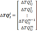
where is the ith (
 ) intrinsic torque response in group j.
NOTE: Similarly, concatenate foot angle, velocity, and acceleration, and first and second derivatives of the intrinsic torque of the jth group to be used in step 2.2.2.11.2. - Place the foot angle, velocity, acceleration and jerk, as well as the first and second derivative of the torque of the group j together to form the regressor matrix:

- Find the intrinsic stiffness parameters for the jth group using the backslash (\) operator:

- Extract the fourth element of
 as the low frequency intrinsic stiffness
 .
.
- Concatenate all the intrinsic torque responses in the jth bin to form the vector
- Perform steps in section 2.2.2.11 for all groups (bins) and estimate the corresponding low frequency intrinsic stiffness.
- Divide all the estimated low frequency stiffness values by the subject’s critical stiffness:

where m is the subject’s mass, g is gravitational acceleration, and is the height of the body’s center of mass above ankle axis of rotation, derived from anthropometric data30. This gives the normalized stiffness (
 ).
). - Convert the ankle background torque to ankle background COP position (
 ) by dividing the ankle background torques with the corresponding measured vertical forces.
 - Plot
 as a function of center of pressure.

where


- Differentiate the foot signal once to obtain foot velocity (
- Experiment
Access restricted. Please log in or start a trial to view this content.
Results
Pseudo random ternary sequence (PRTS) and TrapZ signals
Figure 2A shows a PRTS signal, which is generated by integrating a pseudo random velocity profile. For each sample time
Access restricted. Please log in or start a trial to view this content.
Discussion
Several steps are critical in performing these experiments to study human postural control. These steps are associated with the correct measurement of the signals and include: 1) Correct alignment of the shank ankle axis of rotation to that of the pedals, for the correct measurement of ankle torques. 2) Correct set-up of the range finders to ensure they work in their range and are not saturated during the experiments. 3) Measurement of EMG with good quality and minimal cross talk. 4) Application of appropriate perturbati...
Access restricted. Please log in or start a trial to view this content.
Disclosures
The authors have nothing to disclose.
Acknowledgements
This article was made possible by NPRP grant #6-463-2-189 from the Qatar National Research and MOP grant #81280 from the Canadian Institutes of Health Research.
Access restricted. Please log in or start a trial to view this content.
Materials
| Name | Company | Catalog Number | Comments |
|---|---|---|---|
| 5K potentiometer | Maurey | 112P19502 | Measures actuator shaft angle |
| 8 channel Bagnoli surface EMG amplifiers and electrodes | Delsys | Measures the EMG of ankle muscles | |
| AlienWare Laptop | Dell Inc. | P69F001-Rev. A02 | VR-ready PC laptop |
| Data acquisition card | National instruments | 4472 | Samples the analogue signals from the sensors |
| Directional valve | REXROTH | 4WMR10C3X | Bypasses the flow if the angle of actuator shaft goes beyond ±20° |
| Full body harness | Jelco | 740 | Protect the subjects from falling |
| Laser range finder | Micro-epsilon 1302-100 | 1507307 | Measures shank linear displacement |
| Laser range finder | Micro-epsilon 1302-200 | 1509074 | Measures body linear displacement |
| Load cell | Omega | LC302-100 | Measures vertical reaction forces |
| Proportional servo-valve | MOOG | D681-4718 | Controls the hydraulic flow to the rotary actuators |
| Rotary actuator | Rotac | 26R21VDEISFTFLGMTG | Applies mechanical perturbations |
| Torque transducer | Lebow | 2110-5k | Measures ankle torque |
| Virtual Environment Motion Trackers | HTC inc. | 1551984681 | Tracks the head motion |
| Virtual Reality Headset | HTC inc. | 1551984681 | Provides visual perturbations |
References
- Horak, F. B. Postural orientation and equilibrium: what do we need to know about neural control of balance to prevent falls? Age and Ageing. 35, 7-11 (2006).
- Morasso, P. G., Schieppati, M. Can muscle stiffness alone stabilize upright standing? Journal of Neurophysiology. 82 (3), 1622-1626 (1999).
- Kearney, R. E., Hunter, I. W. System identification of human joint dynamics. Critical Reviews in Biomedical Engineering. 18 (1), 55-87 (1990).
- Mirbagheri, M. M., Barbeau, H., Kearney, R. E. Intrinsic and reflex contributions to human ankle stiffness: variation with activation level and position. Experimental Brain Research. 135 (4), 423-436 (2000).
- Weiss, P. L., Hunter, I. W., Kearney, R. E. Human ankle joint stiffness over the full range of muscle activation levels. Journal of Biomechanics. 21 (7), 539-544 (1988).
- Golkar, M. A., Sobhani Tehrani, E., Kearney, R. E. Linear Parameter Varying Identification of Dynamic Joint Stiffness during Time-Varying Voluntary Contractions. Frontiers in Computational Neuroscience. 11, 35(2017).
- Weiss, P. L., Kearney, R. E., Hunter, I. W. Position dependence of ankle joint dynamics--I. Passive mechanics. Journal of Biomechanics. 19 (9), 727-735 (1986).
- Weiss, P. L., Kearney, R. E., Hunter, I. W. Position dependence of ankle joint dynamics--II. Active mechanics. Journal of Biomechanics. 19 (9), 737-751 (1986).
- Engelhart, D., Boonstra, T. A., Aarts, R. G. K. M., Schouten, A. C., van der Kooij, H. Comparison of closed-loop system identification techniques to quantify multi-joint human balance control. Annual Reviews in Control. 41, 58-70 (2016).
- Kiemel, T., Elahi, A. J., Jeka, J. J. Identification of the plant for upright stance in humans: multiple movement patterns from a single neural strategy. Journal of Neurophysiology. 100 (6), 3394-3406 (2008).
- Loram, I. D., Lakie, M. Direct measurement of human ankle stiffness during quiet standing: the intrinsic mechanical stiffness is insufficient for stability. Journal of Physiology-London. 545 (3), 1041-1053 (2002).
- Fitzpatrick, R., Burke, D., Gandevia, S. C. Loop gain of reflexes controlling human standing measured with the use of postural and vestibular disturbances. Journal of Neurophysiology. 76 (6), 3994-4008 (1996).
- Dakin, C. J., Son, G. M. L., Inglis, J. T., Blouin, J. S. Frequency response of human vestibular reflexes characterized by stochastic stimuli. The Journal of Physiology. 583 (3), 1117-1127 (2007).
- Vlutters, M., Boonstra, T. A., Schouten, A. C., vander Kooij, H. Direct measurement of the intrinsic ankle stiffness during standing. Journal of Biomechanics. 48 (7), 1258-1263 (2015).
- Casadio, M., Morasso, P. G., Sanguineti, V. Direct measurement of ankle stiffness during quiet standing: implications for control modelling and clinical application. Gait and Posture. 21 (4), 410-424 (2005).
- Sakanaka, T. E. Causes of Variation in Intrinsic Ankle Stiffness and the Consequences for Standing. , University of Birmingham. Doctoral dissertation (2017).
- Sakanaka, T. E., Lakie, M., Reynolds, R. F. Sway-dependent changes in standing ankle stiffness caused by muscle thixotropy. Journal of Physiology. 594 (3), 781-793 (2016).
- Peterka, R. J., Murchison, C. F., Parrington, L., Fino, P. C., King, L. A. Implementation of a Central Sensorimotor Integration Test for Characterization of Human Balance Control During Stance. Frontiers in Neurology. 9, 1045(2018).
- Engelhart, D., Schouten, A. C., Aarts, R. G., van der Kooij, H. Assessment of Multi-Joint Coordination and Adaptation in Standing Balance: A Novel Device and System Identification Technique. IEEE Transactions on Neural Systems and Rehabilitation Engineering. 23 (6), 973-982 (2015).
- Boonstra, T. A., Schouten, A. C., van der Kooij, H. Identification of the contribution of the ankle and hip joints to multi-segmental balance control. Journal of Neuroengineering and Rehabilitation. 10, 23(2013).
- Forster, S. M., Wagner, R., Kearney, R. E. A bilateral electro-hydraulic actuator system to measure dynamic ankle joint stiffness during upright human stance. Proceedings of the 25th Annual International Conference of the IEEE Engineering in Medicine and Biology Society. , Cancun, Mexico. (2003).
- Davis, J., Hsieh, Y. -H., Lee, H. -C. Humans perceive flicker artifacts at 500 Hz. Scientific Reports. 5, 7861(2015).
- Amiri, P., Kearney, R. E. Ankle intrinsic stiffness changes with postural sway. Journal of Biomechanics. 85, 50-58 (2019).
- van der Kooij, H., van Asseldonk, E., van der Helm, F. C. Comparison of different methods to identify and quantify balance control. Journal of Neuroscience Methods. 145 (1-2), 175-203 (2005).
- Amiri, P., MacLean, L. J., Kearney, R. E. Measurement of shank angle during stance using laser range finders. International Conference of the IEEE Engineering in Medicine and Biology. , Orlando, FL. (2016).
- The SENIAM project. , Available from: http://www.seniam.org/ (2019).
- Jalaleddini, K., Tehrani, E. S., Kearney, R. E. A Subspace Approach to the Structural Decomposition and Identification of Ankle Joint Dynamic Stiffness. IEEE Transactions on Biomedical Engineering. 64 (6), 1357-1368 (2017).
- Amiri, P., Kearney, R. E. A Closed-loop Method to Identify EMG-Ankle Torque Dynamic Relation in Human Balance Control. Conference Proceedings of the Annual International Conference of the IEEE Engineering in Medicine and Biology Society. , Berlin, Germany. (2019).
- Sobhani Tehrani, E., Jalaleddini, K., Kearney, R. E. Ankle Joint Intrinsic Dynamics is More Complex than a Mass-Spring-Damper Model. IEEE Transactions on Neural Systems and Rehabilitation Engineering. 25 (9), 1568-1580 (2017).
- NASA. Anthropometry and biomechanics. , Available from: http://msis.jsc.nasa.gov/sections/section03.htm (1995).
- Peterka, R. J. Sensorimotor integration in human postural control. Journal of Neurophysiology. 88 (3), 1097-1118 (2002).
- Amiri, P., Kearney, R. E. Ankle intrinsic stiffness is modulated by postural sway. Conference Proceedings of the Annual International Conference of the IEEE Engineering in Medicine and Biology Society. , Seogwipo, South Korea. (2017).
- Jeka, J. J., Allison, L. K., Kiemel, T. The dynamics of visual reweighting in healthy and fall-prone older adults. Journal of Motor Behavior. 42 (4), 197-208 (2010).
- Jilk, D. J., Safavynia, S. A., Ting, L. H. Contribution of vision to postural behaviors during continuous support-surface translations. Experimental Brain Research. 232 (1), 169-180 (2014).
- Winter, D. A., Patla, A. E., Prince, F., Ishac, M., Gielo-Perczak, K. Stiffness control of balance in quiet standing. Journal of Neurophysiology. 80 (3), 1211-1221 (1998).
- Pasma, J. H., Boonstra, T. A., van Kordelaar, J., Spyropoulou, V. V., Schouten, A. C. A Sensitivity Analysis of an Inverted Pendulum Balance Control Model. Frontiers in Computational Neuroscience. 11, 99(2017).
- Pasma, J. H., et al. Changes in sensory reweighting of proprioceptive information during standing balance with age and disease. Journal of Neurophysiology. 114 (6), 3220-3233 (2015).
- Pasma, J. H., et al. Impaired standing balance: The clinical need for closing the loop. Neuroscience. , 157-165 (2014).
- Engelhart, D., et al. Impaired Standing Balance in Elderly: A New Engineering Method Helps to Unravel Causes and Effects. Journal of the American Medical Directors Association. 15 (3), (2014).
- Pasma, J. H., Boonstra, T. A., Campfens, S. F., Schouten, A. C., Van der Kooij, H. Sensory reweighting of proprioceptive information of the left and right leg during human balance control. Journal of Neurophysiology. 108 (4), 1138-1148 (2012).
- Goodworth, A. D., Peterka, R. J. Sensorimotor integration for multisegmental frontal plane balance control in humans. Journal of Neurophysiology. 107 (1), 12-28 (2012).
- Kiemel, T., Zhang, Y., Jeka, J. J. Identification of neural feedback for upright stance in humans: stabilization rather than sway minimization. Journal of Neuroscience. 31 (42), 15144-15153 (2011).
- van der Kooij, H., van Asseldonk, E. H. F., Geelen, J., van Vugt, J. P. P., Bloem, B. R. Detecting asymmetries in balance control with system identification: first experimental results from Parkinson patients. Journal of Neural Transmission. 114 (10), 1333(2007).
- Fujisawa, N., et al. Human standing posture control system depending on adopted strategies. Medical and Biological Engineering and Computing. 43 (1), 107-114 (2005).
- Johansson, R., Magnusson, M., Fransson, P. A., Karlberg, M. Multi-stimulus multi-response posturography. Mathematical Biosciences. 174 (1), 41-59 (2001).
- Jeka, J., Oie, K., Schöner, G., Dijkstra, T., Henson, E. Position and Velocity Coupling of Postural Sway to Somatosensory Drive. Journal of Neurophysiology. 79 (4), 1661-1674 (1998).
- Peterka, R. J., Benolken, M. S. Role of somatosensory and vestibular cues in attenuating visually induced human postural sway. Experimental Brain Research. 105 (1), 101-110 (1995).
- Maki, B. E., Fernie, G. R. A system identification approach to balance testing. Progress in Brain Research. 76, 297-306 (1988).
- Johansson, R., Magnusson, M., Akesson, M. Identification of human postural dynamics. IEEE Transactions on Biomedical Engineering. 35 (10), 858-869 (1988).
- Maki, B. E., Holliday, P. J., Fernie, G. R. A Posture Control Model and Balance Test for the Prediction of Relative Postural Stability. IEEE Transactions on Biomedical Engineering. BME-34. 10 (10), 797-810 (1987).
- Werness, S. A., Anderson, D. J. Parametric analysis of dynamic postural responses. Biological Cybernetics. 51 (3), 155-168 (1984).
- Hwang, S., Agada, P., Kiemel, T., Jeka, J. J. Identification of the Unstable Human Postural Control System. Frontiers in Systems Neuroscience. 10, 22(2016).
- Ishida, A., Imai, S., Fukuoka, Y. Analysis of the posture control system under fixed and sway-referenced support conditions. IEEE Transactions on Biomedical Engineering. 44 (5), 331-336 (1997).
- Ishida, A., Miyazaki, S. Maximum likelihood identification of a posture control system. IEEE Transactions on Biomedical Engineering. 34 (1), 1-5 (1987).
- Ljung, L. System Identification: Theory for the User. , Prentice-Hall, Inc. Upper Saddle River, NJ. (1986).
- Forssell, U., Ljung, L. Closed-loop identification revisited. Automatica. 35 (7), 1215-1241 (1999).
- Horak, F. B., Nashner, L. M. Central programming of postural movements: adaptation to altered support-surface configurations. Journal of Neurophysiology. 55 (6), 1369-1381 (1986).
Access restricted. Please log in or start a trial to view this content.
Reprints and Permissions
