This manuscript describes a protocol for neutron radiography and computed tomography of biological samples using a High Flux Isotope Reactor (HFIR) CG-1D beamline to measure a metal implant in a rat femur, a mouse lung, and an herbaceous plant root/soil system.
Method Article
Neutron Radiography and Computed Tomography of Biological Systems at the Oak Ridge National Laboratory's High Flux Isotope Reactor
* These authors contributed equally
In This Article
Summary
Abstract
Neutrons have historically been used for a broad range of biological applications employing techniques such as small-angle neutron scattering, neutron spin echo, diffraction, and inelastic scattering. Unlike neutron scattering techniques that obtain information in reciprocal space, attenuation-based neutron imaging measures a signal in real space that is resolved on the order of tens of micrometers. The principle of neutron imaging follows the Beer-Lambert law and is based on the measurement of the bulk neutron attenuation through a sample. Greater attenuation is exhibited by some light elements (most notably, hydrogen), which are major components of biological samples. Contrast agents such as deuterium, gadolinium, or lithium compounds can be used to enhance contrast in a similar fashion as it is done in medical imaging, including techniques such as optical imaging, magnetic resonance imaging, X-ray, and positron emission tomography. For biological systems, neutron radiography and computed tomography have increasingly been used to investigate the complexity of the underground plant root network, its interaction with soils, and the dynamics of water flux in situ. Moreover, efforts to understand contrast details in animal samples, such as soft tissues and bones, have been explored. This manuscript focuses on the advances in neutron bioimaging such as sample preparation, instrumentation, data acquisition strategy, and data analysis using the High Flux Isotope Reactor CG-1D neutron imaging beamline. The aforementioned capabilities will be illustrated using a selection of examples in plant physiology (herbaceous plant/root/soil system) and biomedical applications (rat femur and mouse lung).
Introduction
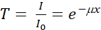
The principle of neutron radiography (nR) is based on the attenuation of neutrons through the matter that they traverse. Unlike X-rays that are scattered by the electron cloud of an atom, neutrons can be absorbed or scattered by its nucleus. Neutrons are sensitive to light elements, such as hydrogen (H), and can consequently be used to radiograph biological applications such as animal1,2,3,4,5,6,7 or human tissues8,9 and below-ground soil/root systems10,11,12,13,14,15. Neutron imaging is a complementary technique to X-ray imaging, which is capable of detecting heavy elements16,17,18. Attenuation-based nR is governed by the linear attenuation coefficients of the materials within the sample and by the thickness of the sample, as described by the Beer-Lambert law, which states that the transmitted beam is directly proportional to the amount of material and the path length through the material. Thus, the transmittance, T, can be calculated as:
 (1)
(1)
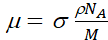
where I0 and I are, respectively, the incident and transmitted beam intensities; µ and x are the linear attenuation coefficient and the thickness of a homogeneous sample, respectively. The attenuation coefficient µ is given by:
 (2)
(2)
where σ is the sample's neutron attenuation cross-section (both scattering and absorption), ρ is its density, NA is Avogadro's number, and M is its molar mass.
Contrast in radiography of biological samples using low-energy neutrons (i.e., energies below 0.5 eV) is mostly due to a change in the density of H (for a fixed sample thickness). This is due to the probability of interaction of a neutron with the H nucleus, which is greater than with other nuclei present in biological samples, and the fact that the density of the H atom is paramount as it is the most abundant atom in biological samples.
Since its early stages, nR and neutron computed tomography (nCT) have been extensively used for materials and engineering applications19,20,21,22,23. The first demonstration experiments of neutron sensitivity to H in biological samples began in the mid-1950s24 with the measurements of plant specimens. The work continued through the 1960s with, for example, the radiography of a human chest25 or rats26, in which the use of contrast agents, such as gadolinium oxide (Gd2O3), was explored. Moreover, it was hypothesized that contrast in human tumor tissue versus normal tissue was due to a local increase in H content. During these initial trials, it was concluded that increased neutron flux and spatial resolution would improve the quality of nR and would likely increase its popularity as a complementary technique for industrial or biomedical applications. The most recent studies comprise nR and nCT measurements performed on cancer tissue specimens1 and sections of animal organs2,3,27 for biomedical and forensic applications.
Located at the Oak Ridge National Laboratory, Oak Ridge, TN, the High Flux Isotope Reactor (HFIR) is a powerful neutron source that produces neutrons by fission reaction. These neutrons have energies in the order of 2 MeV and are "cooled" in the reactor pool by kinetic reactions with heavy water to reach energies in the order of 100-300 eV. The optimization of a neutron experiment, whether scattering or imaging, starts with the understanding of the neutron source and beamline properties such as its beam intensity, energy distribution, and the effect of background (fast neutrons, delayed neutrons, gamma rays). In the HFIR cold guide hall where the imaging beamline is located, neutrons are further "cooled" by kinetic interactions with a liquid H moderator. They are then transported in a curved guide system away from the line of sight of the source, thus eliminating fast neutrons and gamma pollution. As illustrated in Figure 1, the CG-1D neutron-imaging beamline28,29 is placed on a cold guide, implying that the neutron energy range varies from a few meV to a few tens of eV (in this case, the corresponding usable neutron wavelength ranges from 0.8 to 10 Å) with a flux in the range of 107 n/(cm2∙s) at the sample position. A motorized aperture/diffuser system defines the pinhole geometry of the imaging instrument. Neutrons travel a distance of 6.59 m in a helium (He) filled flight tube with aluminum (Al) windows on each end. Flight tubes are used to transport neutrons while limiting air scatter such that the loss in beam intensity is minimum. For the measurements described in this manuscript, the diffuser is made of a 1 mm thick 50 nm aluminum oxide (Al2O3) nano-powder encased in an Al container. The diffuser reduces the beam artifacts coming from the neutron guide (which are magnified by the pinhole geometry of an imaging beamline), otherwise sharp horizontal and vertical intensity fluctuations are visible in the radiograph and normalization of the data becomes challenging. For the experiments illustrated here, neutrons are converted to light using a 25-μm-thick lithium-6 fluoride/zinc sulfide phosphor (6LiF/ZnS:Ag).
Collimation optimization depends on the sample-to-detector position, the required spatial resolution, and acquisition time. When the sample sits a few cm away from the scintillator, high collimations (L/D above 800, where L is the distance from the pinhole aperture of diameter, D, and the detector) yield better spatial resolution at the cost of neutron flux. Low collimation (L/D below 800) is preferable for in situ dynamic studies when time resolution prevails over spatial resolution. For the measurements described in this manuscript, L/D and spatial resolution were approximately 355 and 75 μm, respectively. Temporal resolution varied based on the signal-to-noise ratio (SNR). The sample was positioned as close to the scintillator as possible to reduce geometrical distortion such as blurring. Translation and rotation stages are available to set the sample close to the detectors and perform computed tomography (CT). CG-1D offers three types of detectors: a charge-coupled device (CCD) with 2048 pixels x 2048 pixels with a pixel pitch of 13.5 μm, a scientific complementary metal-oxide semiconductor (sCMOS) detector with 2560 pixels x 2160 pixels with a pixel pitch of 6.5μm, and a micro-channel plate (MCP) detector30,31 with 512 pixels x 512 pixels with a pixel size of 55μm. Scattered neutrons are absorbed with ~5 mm thick boron rubber to protect the detector chip from seeing neutrons. This absorption generates gamma rays that can be stopped by lead (Pb) placed between the boron rubber and the detector. Each detector is optimized for a different field-of-view (FOV) as well as spatial and time resolutions. For the rat femur and the mouse lung measurements, the CCD detector was utilized for its large FOV capability (~ 7 cm x 7 cm) and reasonable spatial resolution of approximately 75μm. The plant root/soil system’s nCT was performed with the sCMOS, as the goal was to acquire nCTs as quickly as possible at the cost of FOV (which was limited to ~ 5 cm x 4.2 cm); thus, spatial resolution evidently suffered. In these detectors, neutrons are either converted to light or an alpha particle for detection purposes. Rotating the sample around its vertical axis and acquiring radiographs at consecutive rotation angles allows the acquisition of nCT. The 3-dimensional volumetric rendered model of the sample under investigation is obtained by utilizing the in-house iMARS3D python-based Jupyter filtered-back-projection (FBP) notebook, pyMBIR or a commercial software, all described below.
Finally, neutrons that have not interacted with the sample or the detector are collected in a beam stop position approximately 1 m downstream from the detector system to minimize background noise. The CG-1D beam stop is 0.75 m wide, 0.5 m tall and 35 mm thick and made of B4C in epoxy. The beam stop is reinforced with 10 mm of 95% enriched lithium carbonate (6Li2CO3) in a fire-resistant epoxy where the neutron beam hits, with a cavity lined with 6Li, lead (Pb) and steel designed to contain the high rate of secondary gamma rays. The beam stop is directly attached to the steel shielding wall of the beamline. A photograph of the CG-1D beamline is given in Figure 2.
Three reconstruction software were used to reconstruct the three experimental data in 3D, respectively. The mouse lung sample reconstruction was performed using Octopus32, a commercial reconstruction software that utilizes FBP. Octopus software sits on a server PC and can be used to reconstruct data collected at the beamline. A reconstruction software, named iMARS3D, is available at CG-1D. It is based on the open source code TomoPY33 with added features such as automated tilt correction, post-processing filters, etc. iMARS3D includes pre-processing of the data (subtraction of the background and noise), cropping, median filtering (to correct for gamma strikes and dead pixels), automated beam intensity fluctuation correction and sample tilt correction. Once sinograms are created, further data processing such as ring artifact removal and smoothing are an option. The different steps of the reconstruction are saved on the analysis server (and later moved in the proposal shared folder), while the final 2D slices are immediately stored in the proposal shared folder. The rat femur was reconstructed using iMARS3D. The plant root/soil sample was pre-processed by median filtering the data using TomoPY followed by tilt axis correction using Python’s SciPy library. The reconstruction was carried out using a python package developed in-house termed - pyMBIR (built using kernels from the ASTRA toolbox34) which implements a suite of tomographic algorithms from the baseline FBP to advanced model-based iterative reconstruction techniques35 that can obtain high quality reconstructions from extremely sparse and noisy neutron data sets. All rendered volumes based on the reconstruction tools aforementioned are represented in attenuation contrast. All visualization was performed using the commercial visualization, segmentation and data analysis software package AMIRA36.
This manuscript aims to demonstrate the procedure of using neutron imaging (nR and nCT) at the HFIR CG-1D beamline. This study also illustrates the current state-of-the-art nR and nCT capabilities for biological samples, specifically a mouse lung, a rat bone, and plant root/soil systems. The mouse lung was chosen to illustrate the complementarity of neutrons to measure the lung tissue, whereas X-rays are mostly sensitive to bones. The bone sample, a rat femur, had a titanium (Ti) implant, thus illustrating the contrast between the bone and the metal, and the opportunity to see the bone/metal interface (which is difficult to measure with X-rays as metals strongly attenuate them4). Finally, the plant-root water system illustrates the three-dimensional (3D) capability of nCT to measure root/soil systems in situ. It additionally shows the advantages/disadvantages of using nR for biological samples. Evidently, this method can be safely used to measure water dynamics in a plant-root system but cannot be considered as a live animal or human imaging technique due to the risks associated with radiation exposure, thus limiting studies to either (dead) mice or pathology-like measurements wherein, for example, a tissue sample is resected from a patient (animal or human) and prepared by fixation before being measured in a neutron beam.
Protocol
1. Instrument setup (see Figure 3, section 3)
- On the beamline computer, open a terminal window, type css, and then press Enter to launch the user interface.
- If not opened by default, choose the User Home option in the Menu tab to open the Experimental Physics and Industrial Control System (EPICS) Imaging Interface.
- Using the first tab (called Proposal/Camera/SE Device) of the interface, select the beamline optics by clicking on the Optics button next to Camera/Detectors, i.e., the pinhole aperture size and opening of the slit system by clicking on the Slits button.
- Bolt the rotation stage onto the XY stages, where the sample is to be placed, and position the detector (sCMOS or CCD).
- For the CCD or the sCMOS detector, select the lens with the magnification that provides the desired spatial resolution and focal length, in consultation with the instrument team. Using light first, focus the camera by either moving the detector closer or further from the mirror, or by manually tuning the lens at a fixed detector position. Focus the image at the location of the neutron scintillator.
- For the CCD or the sCMOS detector, fine-tune the lens focus with neutrons using a neutron-absorbing resolution mask37 placed against the detector scintillator. Collect successive radiographs using different settings (i.e., different detector positions from the mirror automated by moving the detector motor in EPICS).
- Compare radiographs by evaluating line pairs in ImageJ/Fiji39 or a similar image software tool.
- When appropriate, secure the sample in a suitable container (Al container and/or Al heavy-duty foil), placing the sample on the rotation stage as close as possible to the detector. Shield the detector and equipment using neutron (boron rubber) and gamma (Pb bricks) shielding.
- Measure the sample-to-detector distance, and remove the sample. Replace it with the resolution mask to evaluate the pixel size at sample position in this beamline configuration. Using a known feature dimension, evaluate the number of pixels across the feature to determine the pixel size.
- Reposition the sample on the rotation stage.
- Using the EPICS interface and the Align Sample tab, align the sample with the neutron beam by taking successive fast (ms to 1 s) radiographs while the sample is moving until it is in full view of the detector. Save the sample alignment file as a .csv file, which will be reused before the CT scan starts.
- Before starting the CT scan, use the automated CT Alignment Check option (in the Alignment tab) to verify that the sample remains in the field-of-view at different angles by assessing radiographs as they are generated at different sample orientations with the beam.
2. Specimen preparation and data acquisition strategy
NOTE: The animal sample protocols were approved by the University of Tennessee’s Institutional Animal Care and Use Committee for the mouse lung and the Rush University Medical Center Institutional Animal Care and Use Committee for the rat femur.
- Rat femurs
- Implant Ti6Al4V rods (1.5 mm diameter and 15 mm length) into the femurs of male Sprague-Dawley rats, placing them within the intramedullary space through the distal femoral condyles.
- Sacrifice the rats after 12 weeks, and harvest the femurs. Remove all soft tissue (which contributes to neutron attenuation), and freeze the femurs with implants in saline-soaked gauze. Fully submerge 2-inch squared gauze sponges in phosphate-buffered saline (PBS), and wrap each sample fully in these soaked sponges (see the Table of Materials).
- Thaw the femurs to room temperature for X-ray-based microCT scans38, before transporting them in a frozen state to the HFIR.
- Prior to nCT, rethaw the sample, and bring it to room temperature at the HFIR Biohazard Safety Level 2 (BSL2) laboratory located close to the CG-1D neutron imaging beamline. Once at room temperature, wrap the sample in heavy-duty Al foil and place it in an Al cylinder.
- Position the cylinder vertically on the rotation stage at the beamline, and scan the femur at the beamline at room temperature from 0 to 360°, with a stepping angle of 0.25°. Acquire each radiograph for 50 s.
NOTE: Considering dead time for the rotation stage movement and transfer of each radiograph from the CCD to the data acquisition computer, the total time of the scan was approximately 24 h.
- Once the nCT is completed and the sample has been authorized to be removed from the beamline, bring the sample back to the BSL2 lab, remove the containment, and refreeze the sample to preserve it for further experimental measurements.
- Mouse lungs
- Resect lung tissue from a dead mouse used for experiments unrelated to this study. Fix the sample in a solution of 70% ethanol prior to the neutron experiments.
- Wrap the tissue in heavy-duty Al foil and transport it from the BSL2 lab directly to the CG-1D beamline. Insert the sample in an Al cylinder for double containment and to maintain the sample position in the beam during the nCT scan.
- Position the sample close to the CCD, and perform the scan overnight at room temperature.
NOTE: Each radiograph was 150 s, and the rotation stepping angle was 0.5°, from 0 to 182°. The total time for the scan was around 16 h.
- Herbaceous plant root/soil system
NOTE: As with other biological samples, plant-soil systems are limited in size due to the strong attenuation of hydrogen, particularly water in the soil or plant roots. Seeds or ramets may be planted in containers (Al or quartz-both having low neutron attenuation cross-sections), or a more mature plant can be transplanted into a container.- Carefully excavate and transplant a local herb growing onsite (here, mulberry weed (Fatoua villosa (Thunb.) Nakai) into an Al container of cross-section of 2.38 cm x 2.58 cm, a height of 6.3 cm, a wall thickness of 0.055 cm, and containing pure sand (SiO2).
- Rinse the plant roots with deionized water, and carefully display them within the Al container while filling the container with a slurry of wet sand.
NOTE: When filling containers with soil, it is important to use wet soil, as dry soil will separate out by particle size and create textural artifacts in the containers12,13. - After planting, measure the saturated weight of the plant system, and weigh the plant system every day to assess the rate of water use. Apply water either to the top surface of the soil or through a port or hole at the bottom of the container using a tube or syringe.
NOTE: Here, the plant system was placed on a scale, and water was applied to the top each day to replace daily water use based on weight. Water can be withheld prior to imaging to reduce soil water content and enhance contrast in the roots. - Propagate the plant system in an onsite growth chamber with controlled temperature and light12. Maintain the plant system for 1 week prior to imaging to allow for plant root acclimation to the Al container.
NOTE: Once imaging begins, do not water the plant. - Perform the nCT scans in ~1.75 h each, and continuously scan over a period of 2.5 days to map dynamic 3D changes in soil and plant water content. For these measurements, decrease the spatial resolution to a few hundred μm in favor of time resolution (i.e., faster acquisition time for each projection).
NOTE: Each CT scan was performed with a rotation angle of 0.93° and an acquisition time of 10 s per projection. For the purpose of this manuscript, only the first CT scan is presented.
3. Data acquisition
NOTE: The data acquisition system at CG-1D utilizes the EPICS software40. EPICS is developed to guide the experimental protocol and minimize human error; this interface logically steps through the different necessary steps prior to measuring a sample, as illustrated in Figure 3. The EPICS data acquisition protocol is as follows (Figure 3). The left section provides a status of the ongoing experiment, along with motor positions and experiment details (sample information, proposal number, and team members). Each experiment is associated with a proposal number, and one or multiple samples. Proposal information such as team members and selected sample name are also available on the right side (first tab named “Proposal/Camera/Sample Environment Device”). The center section comprised the current radiograph with a dynamic range scale bar on the side, along with status and log information below the image.
- Select the first EPICS tab titled Proposal/Camera/SE Device. Click on the Switch Proposal or Sample button. Select the project number and sample ID# to be measured in the List of Proposals (left) and Sample (right) that have replaced the previous tab.
- Use the back arrow to come back to the main EPICS interface. Select the detector to be used (sCMOS or CCD) by choosing one of the four available detectors (Andor CCD, Andor sCMOS, SBIG CCD, or MCP) in the Camera/Detector option list.
NOTE: The SBIG CCD is used for testing by the instrument and can be ignored for the present manuscript. - Select the rotation stage to be used in the Sample Environment Device section.
- First, click on Rotation Stage (CT Scan) in the Sample Environment Device list. Then, select one of the rotation stages (which corresponds to the sample to be scanned).
- Finally, at the bottom of the tab, select the Data Acquisition Mode. In this case, select the first option, White Beam.
NOTE: The mode of acquisition is either white beam (taking the whole range of neutron wavelength) or monochromatic at the CG-1D beamline. - Select the second EPICS tab titled Align Sample. Type a sample file name, and press Enter. Repeat the process for the sub folder name.
NOTE: The EPICS interface is programmed to automatically save data in the proper experimental directories, which the in-house reconstruction software uses to produce 2-dimensional (2D) slices of the 3D object under investigation. The second tab, Align Sample, allows the alignment of the sample using radiographs that are a few seconds only as these radiographs are not used later for data processing and analysis. Once all motors are positioned properly, their positions can be saved in a .csv file format; thus, each sample alignment has its corresponding .csv file that can be called back to position the samples for CT scans at a later time. - Skip the alignment of the three motors, i.e., assume that the sample is aligned and ready for CT. Select a desired acquisition time, and click on the Take Quick Images button. Collect a series of radiographs with different acquisition times to evaluate SNR.
- Open ImageJ/Fiji; drag and drop the different radiographs. Plot a profile going from the sample to an open area; evaluate SNR.
- If multiple samples are set on the XY stage (multiple rotation stages, each for one sample), record each sample position after alignment, and save the data as .cvs file by clicking on the Save in a File button.
- Select the third EPICS tab titled Collect Data to set up the CT scan parameters. Type a file name on the first writable line, and press Enter. Repeat for the sub-folder name.
NOTE: The layout of the Collect Data tab depends on the selection of a series of time-elapsed radiographs (no SE) or CT scans (selection of a rotation stage) in the first tab. - In the Align Sample Using the Saved File section, select the file that previously recorded the sample motor positions (step 1.8). Use the Recently Saved Files to browse through the recently saved sample alignment files. Click on Align Using File to make the sample go back in position in the neutron beam.
- Calculate the number of projections required for the CT based on Nyquist's sampling theorem. Calculate the number of pixels across the sample horizontal dimension, and multiply by 1.5 to obtain the number of needed projections to fulfill Nyquist's sampling.
- Enter the Rotation Start Angle (usually 0°), Rotation End Angle (usually 180°), Rotation Step Size, the Number of Images per Step (usually set to 1), and the Exposure time for each image. Start the CT scan by clicking on the Collect Data button.
4. Volume reconstruction and data processing/analysis
NOTE: All CG-1D software tools for data normalization, reconstruction, and analysis are available on the ORNL facility's Python repository and on the facility's analysis servers. For 2D measurements, pre-processing can be done using Jupyter Python notebooks41. An illustration of a notebook is available in Figure 4. One can load and preview their data before selecting a region of interest outside the sample that is used to normalize to 1 (or 100%) transmission any beam fluctuation. These notebooks can be adapted to each measurement, making pre-processing a straightforward effort. Furthermore, 2D analysis can be performed in the same notebook such as tracking kinetic changes (i.e. water uptake in a sample) in a sample through time.
- Log on to the Linux analysis server using the username and password. Open the web browser, and type jupyter.sns.gov.
- Open the python Jupyter notebook named iMARS3D. Run the first few lines of the code (which loads the tools necessary to run iMARS3D). Load data, flat, and dark field. Verify that all the three data sets are properly loaded.
- Proceed with cropping the data, filtering (as necessary), normalization (with automated sample tilt correction), and volumetric reconstruction (a long process). Save the data in the project number folder named Shared. After turning on AMIRA36, which is also available on the facility analysis servers, load the reconstructed slices in the software, and proceed with visualization, further filtering, and analysis.
Results
Figure 5A is a photograph of a representative rat femur of similar size as the one measured; Figure 5B,C represent the nCT of a rat's femur with the Ti implant. Figure 5B shows the false color attenuation-based nCT of the femur, while Figure 5C represents a diagonal cut through the bone with the same orientation as in Figure 5B to reveal the Ti implant (in gray scale) resembling an X-ray medical CT. This implant does not interact with neutrons as much as the bone material; thus, its attenuation is minimum, and it appears darker (i.e., less attenuating) than the surrounding bone. Trabecular bone, which is present within the medullary space of the femur, is clearly visible at the proximal end of the sample (red arrows in Figure 5B).
Figure 6A,B show representative photographs of the ethanol-fixed mouse lung, in two different positions, used for nCT to demonstrate the ability of neutrons to detect soft tissue specimens. The reconstructed volume of the mouse lung obtained from nCT are shown in Figure 6C,D, positioned in a similar fashion as Figure 6A,B. A cut through the right lobe of the lung is illustrated in Figure 6E. Despite the relatively small size of the sample, neutron sensitivity is clearly demonstrated by a detection of structure of lung at ~75 µm spatial resolution. As expected, the range of attenuation is quite broad, with a large portion corresponding to a low to medium neutron attenuation as lungs have a sponge-like structure containing air.
Figure 7A shows a photograph of the plant sample, while Figure 7B represents the false color volumetric rendering of the plant root/soil system in a rectangular Al container (which is not visible because Al is mostly transparent to neutrons). Compared to the previous data sets, SNR is poorer, as expected, as the data were acquired faster to track the dynamic movements of water uptake in the root in 3D over 2.5 days. Thus, each CT scan was optimized to be measured within a ~1.75 h window. Despite poor SNR, the root system in soil is clearly visible in the vertical cuts of the sample displayed in Figure 7C,D in false color.

Figure 1: Schematic drawing of the HFIR CG-1D neutron imaging beamline. The imaging beam is defined by the aperture system that defines a cone beam geometry. The beam is transported via a He-filled flight tube with beam scrapers to remove unwanted stray neutrons. A borated rubber liner inside the flight tube decreases background from neighboring beamlines. Abbreviations: HFIR = High Flux Isotope Reactor; He = helium; L = distance from the pinhole aperture of diameter, D, and the detector. Please click here to view a larger version of this figure.
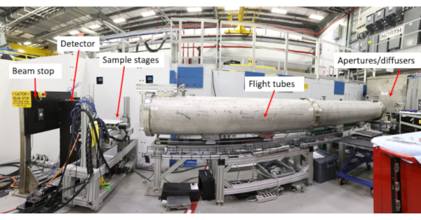
Figure 2: The CG-1D neutron imaging facility at the High Flux Isotope Reactor. The photograph shows, front right to left, the flight tubes, sample area, and beam stop. The neutron beam is coming from the right side of the photograph. The flight tube has been signed by the scientific and industry research communities that utilize the instrument. Please click here to view a larger version of this figure.
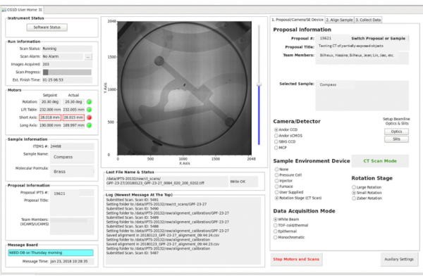
Figure 3: EPICS interface. The CG-1D EPICS interface is divided into three sections: the status section (left), the display area (in this example, a raw radiograph of a brass nautical sundial), and the parameter input for 2D and 3D imaging. Abbreviations: EPICS = Experimental Physics and Industrial Control System; 2D = two-dimensional; 3D = three-dimensional. Please click here to view a larger version of this figure.
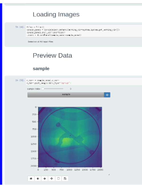
Figure 4: A screenshot of a Jupyter notebook. This notebook is utilized to preview a set of radiographs before normalizing them. In this example, the same brass nautical sundial shown in Figure 3 is visualized. Please click here to view a larger version of this figure.
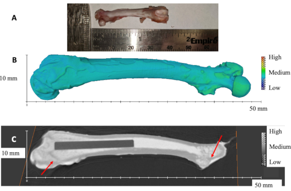
Figure 5: Rat femur with titanium implant. (A) Photograph of a representative rat femur. (B) 3D rendered volume of rat femur obtained from nCT. (C) Diagonal slice showing the titanium rod inside the femur. Red arrows show the trabecular bone. The scale bars are presented by the x and y axes, respectively. Please click here to view a larger version of this figure.
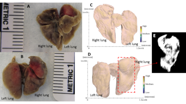
Figure 6: Mouse lung nCT. (A) and (B) Representative photographs of mouse lung. (C) and (D) Attenuation-based 3D rendered volume of mouse using the same positioning as (A) and (B). (E) Representative slice through the right lobe of the mouse lung (D) showing a structure of lung obtained with a different gradient of neutron attenuation (mostly low attenuation). Please click here to view a larger version of this figure.
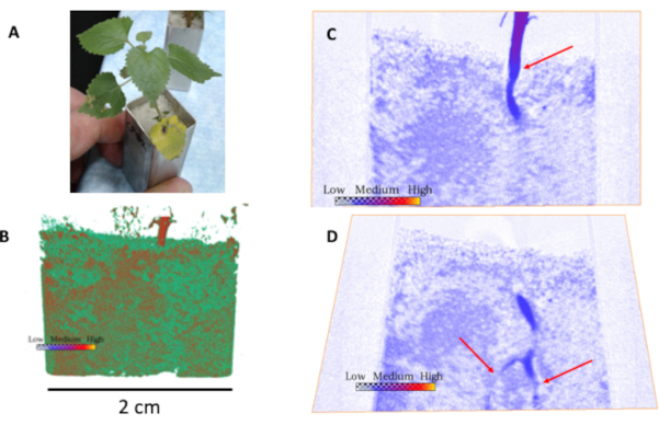
Figure 7: Neutron computed tomography and slices through the plant root/soil system. (A) Photograph of plant sample. (B) 3D rendered volume from neutron computed tomography of the plant showing the stem above ground, and the soil system with water (in red). (C) and (D) are cuts through the sample angled to show the stem and roots in the soil (red arrows). Darker blue areas in the soil indicate the presence of water. Please click here to view a larger version of this figure.
Discussion
Neutron radiography and CT of biological samples are promising imaging techniques that are complementary to X-ray imaging or magnetic resonance imaging. The critical steps in performing a neutron imaging experiment of a biological sample are related to its preparation and its containment at the beamline. Optimization of an experiment is driven by the scientific question to be answered. If the science question requires high spatial resolution to observe a phenomenon, then long acquisition times are required, and the drawback of nCT (with cm size field-of-view) is that it takes hours to perform a scan. This is mostly due to the difference in overall neutron flux available at a reactor compared to a synchrotron source, where X-ray CT scans can take seconds to minutes for a few mm2 field-of-view. Although the method can be applied to ex vivo tissue samples extracted from animals, it cannot be extended in vivo to live animals or humans due to the radiation exposure risk (such as gamma rays produced by neutrons and neutron interactions with the atoms in the sample). However, it is well-suited for the imaging of plant root/soil interactions (Figure 7) such as water uptake dynamics.
The advantage of using fast nCT for plant dynamics is the sensitivity to H in water and the absence of radiation damage to the plant, unlike X-ray CT. Moreover, unique contrast can be observed from the use of neutrons in bone/metal samples such as a rat femur where the metal is relatively transparent compared to the surrounding tissues (Figure 5), potentially avoiding metal artifacts induced by X-ray CT39. Animal tissues, such as mouse lung (Figure 6), show impressive detection of soft tissue structure because neutrons are sensitive to H, but spatial resolution is somewhat the limiting factor in these measurements. Contrast is provided by the H atoms present in biological samples19,39.
With the advances of novel techniques such as neutron grating interferometry, and the improvement in spatial resolution (a few microns have recently been reported42,43) neutron imaging may offer yet new contrast mechanisms for biological tissues with improved spatial resolution. The exploration of higher energy neutrons (to allow the measurements of thick samples) also promises the ability to measure larger sections of an animal tissue such as an intact mouse, thus offering yet new possibilities for biomedical research.
Disclosures
The authors have nothing to disclose.
Acknowledgements
Part of this research utilized resources at the High Flux Isotope Reactor, operated by ORNL, and sponsored by the U.S. Department of Energy, Office of Science, User Facilities, under contract DE-AC05-00OR22725 with UT-Battelle, LLC. Part of this research was supported by ORNL through the Eugene Wigner Distinguished Staff Fellowship program. This research was also sponsored by the DOE Office of Science, Office of Biological and Environmental Research. Rat femoral samples were obtained from experiments performed in collaboration with Dr. Rick Sumner at Rush University Medical Center with funding obtained from the NIH (R01AR066562) and from the Orthopedic Research and Education Foundation-Smith and Nephew award. The team wants to thank the HFIR support teams that enable the use of the neutron scattering beamlines.
Materials
| Name | Company | Catalog Number | Comments |
|---|---|---|---|
| Aluminum containers | custom | Made from aluminum plates or tubing (alternate is quartz), plant and mouse sample | |
| Aluminum foil | Fisher | 01-213-100 | Mouse lung sample containment |
| Deionized water or deuterium oxide | Water or D2O can be used to enhance contrast, plant sample | ||
| Ethanol | Fisher | 04-355-223 | Mouse lung sample |
| Gauze sponges | CardinalHealth | Fully submerged in phosphate-buffered saline (PBS) and used to wrap samples, rat femur sample | |
| Growth chamber | Conviron | A1000 | Any growth chamber or greenhouse with controlled conditions would work, plant sample |
| Laboratory balance | Weighing plant system can be used to measure actual water content in the soils, plant sample | ||
| Pure silica sand | US Silica Co. | Flint#13 | Pure SiO2 provides low neutron attenuation compared to soils, plant sample |
| Sprague-Dawley Rats | Harlan | Order Code: 002-US | Rat femur sample |
| Titanium Rod | Goodfellow | TI007905 | Rat femur sample |
References
- Cekanova, M., Donnell, R., Bilheux, H., Bilheux, J. -C. Neutron imaging: Detection of cancer using animal model. Proceedings of the 2014 Biomedical Sciences and Engineering Conference - 5th Annual ORNL Biomedical Sciences and Engineering Conference: Collaborative Biomedical Innovations - The Multi-Scale Brain: Spanning Molecular, Cellular, Systems, Cognitive, Behaviour. , (2014).
- Bilheux, H. Z., et al. Neutron imaging a. The Oak Ridge National Laboratory: Application to biological research. Proceedings of the 2014 Biomedical Sciences and Engineering Conference - 5th Annual ORNL Biomedical Sciences and Engineering Conference: Collaborative Biomedical Innovations - The Multi-Scale Brain: Spanning Molecular, Cellular, Systems, Cognitive, Behaviour. , (2014).
- Bilheux, H. Z., et al. A novel approach to determine post mortem interval using neutron radiography. Forensic Science International. 251, (2015).
- Isaksson, H., et al. Neutron tomographic imaging of bone-implant interface: Comparison with X-ray tomography. Bone. 103, 295-301 (2017).
- Le Cann, S., et al. Characterization of the bone-metal implant interface by Digital Volume Correlation of in-situ loading using neutron tomography. Journal of the Mechanical Behavior of Biomedical Materials. 75, 271-278 (2017).
- Burca, G., et al. Exploring the potential of neutron imaging for life sciences on IMAT. Journal of Microscopy. 272 (3), 242-247 (2018).
- Metzke, R. W., et al. Neutron computed tomography of rat lungs. Physics in Medicine and Biology. 56 (1), 1-10 (2011).
- Altieri, S., et al. Neutron autoradiography imaging of selective boron uptake in human metastatic tumours. Applied Radiation and Isotopes. 66 (12), 1850-1855 (2008).
- Altieri, S., Bortolussi, S., Bruschi, P., Pedroni, P., Zonta, A. Neutron radiography of human liver metastases after BPA infusion. Proceedings of 11th World congress on Neutron Capture Therapy. , (2004).
- Holz, M., Zarebanadkouki, M., Kaestner, A., Kuzyakov, Y., Carminati, A. Rhizodeposition under drought is controlled by root growth rate and rhizosphere water content. Plant and Soil. 423 (1-2), 429-442 (2018).
- Esser, H. G., Carminati, A., Vontobel, P., Lehmann, E. H., Oswald, S. E. Neutron radiography and tomography of water distribution in the root zone. Journal of Plant Nutrition and Soil Science. 173 (5), 757-764 (2010).
- Warren, J. M., et al. Neutron imaging reveals internal plant water dynamics. Plant and Soil. 366 (1-2), (2013).
- Dhiman, I., et al. Quantifying root water extraction after drought recovery using sub-mm in situ empirical data. Plant and Soil. 424, 73-89 (2018).
- Kroener, E., Zarebanadkouki, M., Kaestner, A., Carminati, A. Non-equilibrium dynamics of rhizosphere. Water Resources Research. 50 (8), 6479-6495 (2014).
- Moradi, A. B., et al. Three-dimensional visualization and quantification of water content in the rhizosphere. New Phytologist. 192 (3), 653-663 (2011).
- Banhart, J., et al. X-ray and neutron imaging - Complementary techniques for materials science and engineering. International Journal of Materials Research. 101 (9), 1069-1079 (2010).
- LaManna, J. M., Hussey, D. S., Baltic, E. M., Jacobson, D. L. Improving material identification by combining x-ray and neutron tomography. Proceedings 10391, Developments in X-Ray Tomography XI. 1039104, (2017).
- Tengattini, A., et al. NeXT-Gremoble, the Neutron and X-ray tomograph in Grenoble. Nuclear Instruments and Methods in Physics Research, Section A: Accelerators, Spectrometers, Detectors and Associated Equipment. 968, 163939(2020).
- Neutron Imaging and Applications. Bilheux, H. Z., McGreevy, R. L., Anderson, I. S. , Springer. Boston, MA, USA. (2009).
- Zhang, P., Wittmann, F. H., Zhao, T. J., Lehmann, E. H., Vontobel, P. Neutron radiography, a powerful method to determine time-dependent moisture distributions in concrete. Nuclear Engineering and Design. 241 (12), 4758-4766 (2011).
- Lobo, R. M., Andrade, A. H. P., Castagnet, M. Hydride embrittlement in zircaloy components. Inac 2011 Int Nucl.Atlantic Conference. , 1-6 (2011).
- Kardjilov, N., et al. New trends in neutron imaging. Nuclear Instruments and Methods in Physics Research, Section A: Accelerators, Spectrometers, Detectors and Associated Equipment. 605 (1-2), 13-15 (2009).
- Schillinger, B., et al. Detection systems for short-time stroboscopic neutron imaging and measurements on a rotating engine. Nuclear Instruments and Methods in Physics Research, Section A: Accelerators, Spectrometers, Detectors and Associated Equipment. 542 (1-3), 142-147 (2005).
- Thewlis, J. Neutron Radiography. British Journal of Applied Physics. 7, 345-350 (1956).
- Anderson, J. Neutron Radiography in Man. British Journal of Radiology. 37, 957-958 (1964).
- Brown, M., Parks, P. B. Neutron radiography in biologic media: techniques, observations, and implications. American Journal of Roentgenology. 106 (3), 472-485 (1969).
- Metzke, R. W., Runck, H., Stahl, C. A., Schillinger, B., Calzada, E. Neutron computed tomography of rat lungs. Physics in Medicine and Biology. 56 (1), 1-10 (2011).
- Crow, L., et al. The CG1 instrument development test station at the high flux isotope reactor. Nuclear Instruments and Methods in Physics Research, Section A: Accelerators, Spectrometers, Detectors and Associated Equipment. 634 (1), 71-74 (2011).
- Santodonato, L., et al. The CG-1D neutron imaging beamline at the Oak Ridge National Laboratory High Flux Isotope Reactor. Physics Procedia. 69, 104-108 (2015).
- Tremsin, A. S., et al. Improved efficiency of high resolution thermal and cold neutron imaging. Nuclear Instruments and Methods in Physics Research, Section A: Accelerators, Spectrometers, Detectors and Associated Equipment. 628 (1), 415-418 (2011).
- Tremsin, A. S., Vallerga, J. V., McPhate, J. B., Siegmund, O. H. W. Optimization of high count rate event counting detector with microchannel plates and quad Timepix readout. Nuclear Instruments and Methods in Physics Research, Section A: Accelerators, Spectrometers, Detectors and Associated Equipment. 787, 20-25 (2015).
- Vlassenbroeck, J., et al. Software tools for quantification of X-ray microtomography at the UGCT. Nuclear Instruments and Methods in Physics Research, Section A: Accelerators, Spectrometers, Detectors and Associated Equipment. 580 (1), 442-445 (2007).
- Gürsoy, D., De Carlo, F., Xiao, X., Jacobsen, C. TomoPy: A framework for the analysis of synchrotron tomographic data. Journal of Synchrotron Radiation. 21 (5), 1188-1193 (2014).
- Pelt, D. M., et al. Integration of TomoPy and the ASTRA toolbox for advanced processing and reconstruction of tomographic synchrotron data. Journal of Synchrotron Radiation. 23 (3), 842-849 (2016).
- Venkatakrishnan, S. V., Cakmak, E., Billheux, H., Bingham, P., Archibald, R. K. Model-based iterative reconstruction for neutron laminography. Conference Record of 51st Asilomar Conference on Signals, Systems and Computers, ACSSC 2017. , (2018).
- Stalling, D., Westerhoff, M., Hege, H. C. Amira: A highly interactive system for visual data analysis. Visualization Handbook. 1, 749-767 (2005).
- Grünzweig, C., Frei, G., Lehmann, E., Kühne, G., David, C. Highly absorbing gadolinium test device to characterize the performance of neutron imaging detector systems. Review of Scientific Instruments. 78 (5), 1-4 (2007).
- Schindelin, J., et al. Fiji: An open-source platform for biological-image analysis. Nature Methods. 9 (7), 676-682 (2012).
- Meagher, M. J., Parwani, R. N., Virdi, A. S., Sumner, D. R. Optimizing a micro-computed tomography-based surrogate measurement of bone-implant contact. Journal of Orthopaedic Research. 36 (3), 979-986 (2018).
- Dalesio, L. R., et al. The experimental physics and industrial control system architecture: past, present, and future. Nuclear Inst. and Methods in Physics Research, A. 352 (1-2), 179-184 (1994).
- Bilheux, J., Lin, J. Y. Y., Bilheux, H. Z. Jupyter notebooks for neutron radiography data processing and analysis. Neutron Radiography-WCNR-11. 15, 198-204 (2020).
- Trtik, P., et al. Improving the spatial resolution of neutron imaging at Paul Scherrer Institut - The Neutron Microscope Project. Physics Procedia. 69, 169-176 (2015).
- Morgano, M., et al. Unlocking high spatial resolution in neutron imaging through an add-on fibre optics taper. Optics Express. 26 (2), 9-12 (2018).
Reprints and Permissions
