

Summary
The present protocol describes a friction testing device that applies simultaneous reciprocal sliding and normal load to two contacting biological counterfaces.
Abstract
In primary osteoarthritis (OA), normal 'wear and tear' associated with aging inhibits the ability of cartilage to sustain its load-bearing and lubrication functions, fostering a deleterious physical environment. The frictional interactions of articular cartilage and synovium may influence joint homeostasis through tissue level wear and cellular mechanotransduction. To study these mechanical and mechanobiological processes, a device capable of replicating the motion of the joint is described. The friction testing device controls the delivery of reciprocal translating motion and normal load to two contacting biological counterfaces. This study adopts a synovium-on-cartilage configuration, and friction coefficient measurements are presented for tests performed in a phosphate-buffered saline (PBS) or synovial fluid (SF) bath. The testing was performed for a range of contact stresses, highlighting the lubricating properties of SF under high loads. This friction testing device can be used as a biomimetic bioreactor for studying the physical regulation of living joint tissues in response to applied physiologic loading associated with diarthrodial joint articulation.
Introduction
Osteoarthritis (OA) is a debilitating, degenerative joint disease that affects more than 32 million American adults, with a healthcare and socio-economic cost of over $16.5 billion1. The disease has classically been characterized by the degradation of articular cartilage and subchondral bone; however, changes to the synovium have recently garnered appreciation as synovitis has been linked to OA symptoms and progression2,3,4. In primary (idiopathic) OA, normal 'wear and tear' associated with aging inhibits cartilage's ability to sustain its load-bearing and lubrication functions. The stresses generated by prolonged sliding contact of articular cartilage layers or sliding contact of cartilage against implant materials have been shown to facilitate delamination wear through subsurface fatigue failure5,6. As a dynamic mechanical environment exists within the joint7,8, the frictional interactions of articular cartilage and synovium may influence joint homeostasis through tissue level wear and cellular mechanotransduction. To study these mechanical and mechanobiological processes, a device has been designed to replicate the motion of the joint with tight control over compressive and frictional loading5,6,9,10,11,12,13.
The present protocol describes a friction testing device that delivers reciprocal, translating motion and compressive load to contacting surfaces of living tissue explants. The computer-controlled device permits user control of the duration of each test, applied load, range of motion of the translation stage, and translation speed. The device is modular, allowing for testing of various counterfaces, such as tissue-on-tissue (cartilage-on-cartilage and synovium-on-cartilage) and tissue-on-glass. In addition to the functional measurements obtained by the tester, tissue and lubricating bath components can be assessed before and after testing to evaluate the biological changes imparted by a given experimental regimen.
Studies of cartilage tribology have been performed for decades, and several techniques have been developed to measure friction coefficients between cartilage and glass and cartilage on cartilage14,15. The different approaches are motivated by the joint and/or the lubrication mechanism of interest. There is often a tradeoff between the control of experimental variables and the recapitulation of physiologic parameters. Pendulum-style devices utilize intact joints as the fulcrum of a simple pendulum where one joint surface translates freely over the second surface14,16,17,18. Instead of using intact joints, friction measurements may be obtained by sliding cartilage explants over desired surfaces14,19,20,21,22,23,24,25. Reported friction coefficients of articular cartilage have varied over a wide range (from 0.002 to 0.5) depending on the operating conditions14,26. Devices have been created to replicate rotary motion23,27,28. Gleghorn et al.26 developed a multi-well custom tribometer to observe cartilage lubrication profiles using Stribeck curve analysis, and a linear oscillatory sliding motion was applied between cartilage against a flat glass counterface.
This device aims to isolate frictional responses and explore the mechanobiology of living tissues under various loading conditions. The device employs a simplified test set-up simulating joint articulation through compressive sliding, which can approximate both rolling and sliding motion with the understanding that the resistance in pure rolling motion is negligible relative to the measured friction coefficient of articular cartilage29. Originally built to study the effects of interstitial fluid pressurization on the frictional response of articular cartilage9, the tester has since been used to explore topics such as frictional effects of removing the superficial zone of cartilage10, lubricating effects of synovial fluid11, cartilage wear hypotheses5,6,30, and synovium-on-tissue friction measurements13. The friction-testing bioreactor can conduct friction experiments under sterile conditions, providing a novel mechanism to explore how frictional forces affect the mechanobiological responses of living cartilage and synovium. This design can be used as a biomimetic bioreactor to study the physical regulation of living joint tissues in response to applied physiologic loading associated with diarthrodial joint articulation.
This study presents a configuration for synovium-on-cartilage friction testing over a range of contact stresses and in different lubricating baths. The articulating surface area of most joints is, to a great extent, synovial tissue31. While synovium-on-cartilage sliding does not occur at primary load-bearing surfaces, the frictional interactions between the two tissues may still have important implications for tissue level repair and cell mechanotransduction. It has previously been shown that fibroblast-like synoviocytes (FLS) residing on the intimal layer of the synovium are mechanosensitive, responding to fluid-induced shear stress32. It has also been demonstrated that stretch33,34 and fluid-induced shear stress35 modulate FLS lubricant production. As such, direct sliding contact between synovium and cartilage may provide another mechanical stimulus to resident cells in the synovium.
Only a few reports on synovium friction coefficients have been published31,36. Estell et al.13 sought to expand on the previous characterization by utilizing biologically relevant counterfaces. With the friction testing device's ability to test living tissues, it is possible to mimic physiologic tissue interactions during joint articulation to elucidate the role of contact shear stress on synoviocyte function and its contribution to the crosstalk between synovium and cartilage. The latter has been implicated in mediating synovial joint inflammation in arthritis and post-injury. Due to the physical proximity of cartilage to synovium and synovial fluid, which contain synoviocytes that exhibit multipotent capacity, including chondrogenesis, it is postulated that synoviocytes play a role in cartilage homeostasis and repair by engrafting to the articular surface. In this context, physical contact and reciprocal shearing of cartilage-synovium and synovium-synovium may increase the accessibility of synoviocytes to regions of cartilage damage37,38,39,40. Studies utilizing synovium-on-cartilage configurations will not only provide insights into joint gross tissue mechanics and tribology, but they may also lead to new strategies for maintaining joint health.
Subscription Required. Please recommend JoVE to your librarian.
Protocol
Juvenile bovine knee joints, obtained from a local abattoir, were used for the present study. Studies with such bovine specimen samples are exempted from Columbia Institutional Animal Care and Use Committee (IACUC).
1. Designing the friction testing device
NOTE: A schematic representation of the friction testing device is shown in Figure 1. The device is built on a rigid base plate (not shown), which serves as a platform for structural support.
- Attach a stepper motor to the horizontal translation stage (see Table of Materials), creating a two-axis friction testing device that delivers reciprocal translating motion to contacting surfaces.
- Mount a multiaxial load cell on the translation stage (see Table of Materials). The mounted load cell will be used to measure the normal load in the z-direction (Fn), and the tangential load in the x-direction (Ft).
- Equip the translation stage with a linear encoder (see Table of Materials) to record the horizontal displacement (ux) of the stage. Further, equip the loading stage with a linear encoder (see Table of Materials) to record the vertical displacement (uz) of the platen.
NOTE: The translation stage encoder records the relative tangential displacement of the contacting surfaces, and this information is used to detect the beginning of each new cycle of reciprocating sliding. - Configure the loading platen (top contacting surface) as a glass, cartilage, or synovium counterface. Connect the platen to the loading stage via a threaded support rod.
- Attach a two-part magnetic base to the top of the load cell (see Table of Materials): (1) a fixed base that is permanently attached to the load cell and (2) a removable base that magnetically connects to the fixed base. Ensure that the two parts form a tight connection.
NOTE: The removable base will hold the translating counterface (bottom contacting surface). - Prescribe a normal load. Use dead weight mounted on linear bearings above the loading platen and support rod. Alternatively, specify a load using the voice coil actuator (see Table of Materials), which can dynamically load the bottom contacting surface41.
- House the device within an aluminum-framed acrylic enclosure (see Table of Materials) to protect its environment from contamination.
NOTE: A custom LabVIEW program controls the device (see Supplementary coding files) with user control of the duration of each test, as well as stage travel path, acceleration (change of direction), and speed. The normal force, tangential force, stage displacement, and creep displacement are monitored throughout the test with data acquisition hardware and software (see Table of Materials).
2. Specimen preparation and mounting
- Prepare for a sterile tissue harvest following the steps below.
NOTE: If a sterile harvest is not desired, proceed to step 2.2.- Sterilize metal tools in an autoclave. Spray joint holders with 70% ethanol and place them in the biological safety cabinet (BSC). Close the cabinet for one ultraviolet (UV) cycle.
- Retrieve the tools from the autoclave. Place the tools, betadine, sterile scalpel blades, and beakers containing 70% ethanol in the BSC.
- Inside the BSC, open the tools and place them in 70% ethanol beakers. Attach the scalpel blades to scalpel handles.
- Prepare the joint for harvest. Spray the outside of the joint with 70% ethanol and wrap in aluminum foil for 30 min. Take care not to break the joint capsule.
NOTE: The juvenile bovine knee joints were received with the femur and tibia cut approximately 15 cm superior and inferior to the joint to ensure an intact capsule. - After 30 min, place the wrapped joint inside the BSC. Open the foil and secure the joint to its holder. Cover the joint in betadine by gently wiping the betadine across the joint surface.
NOTE: Refer to step 2.2 and step 2.3 for synovium-specific instructions and cartilage-specific instructions, respectively.
- Harvest the juvenile bovine synovium following the steps below.
- Secure the tibiofemoral joint capsule using a ring stand (see Table of Materials) with the anterior side facing the dissector. Using forceps and a scalpel blade, sever the patellar tendon using a horizontal incision of 5-10 cm (depending on joint size) superior to the tibia (Figure 2A).
- Hold the detached patella tendon with forceps. Make two anterior-to-posterior cuts in the shape of a V (Figure 2B,C). These cuts should free the patella.
NOTE: As the joint begins to open, be careful not to sever the anterior cruciate ligament (ACL), posterior cruciate ligament (PCL), medial collateral ligament (MCL), lateral collateral ligament (LCL), and meniscus. - Rotate the patella behind the joint or remove it completely from the joint. Carefully remove the tissue superficial to the synovial membrane on the medial and lateral sides of the joint to expose the synovium.
- Using a scalpel blade, trace the outline of the synovium region of interest. Using forceps, grasp one end of the synovium and gently lift to stretch the synovium distal to the underlying bone. Use a scalpel blade to remove the synovium from the bone (Figure 2D,E).
- Place the tissue in appropriate culture media or testing bath solution. The synovium explant may be cultured for a desired experiment or mounted and used for testing.
NOTE: Culture media/testing bath solutions may vary based on a research group's preference. For the custom-made ones used for the present study, please see Table of Materials.
- Harvest the juvenile bovine cartilage (femoral plugs and tibial strips).
- Separate the femur from the tibia by severing the ACL, PCL, MCL, and LCL. Take care not to slice the femoral condyle cartilage or slice through the meniscus to the tibial plateau. Place the separated tissues in their respective holders for dissection (step 2.3.2 for femur and step 2.3.3 for tibia).
- Secure the femur using a ring stand. Using a biopsy punch of desired shape and size, drive the instrument normal to the femoral condyle articular cartilage surface until reaching the bone (Figure 3A).
- Loosen the plug's connection to the bone by moving the punch left to right and forward to backward. Do this without removing the punch.
NOTE: Crackling sounds may be heard as the bone separates from the cartilage. - Remove the punch, and therefore the plug, from the underlying bone (Figure 3B). If necessary, repeat steps 2.3.2, 2.3.2.1, and 2.3.2.2 for the remaining untouched locations on the condyle.
NOTE: In preparation for mounting the femoral plug onto a testing base, the deep side of the plug may need to be shaved flat. This can be done with a box cutter or scalpel. - Place tissue in appropriate culture media or testing bath solution. The femoral plug may be cultured for a desired experiment or mounted and used for testing.
- Loosen the plug's connection to the bone by moving the punch left to right and forward to backward. Do this without removing the punch.
- Secure the tibia in an adjustable holder (see Table of Materials). Remove the meniscus carefully while avoiding contact with the cartilage surface (Figure 4A).
- On the outer edges of the tibial plateau, use a box cutter to cut perpendicular to the cartilage toward the bone. Cut completely through the cartilage to make straight edges/sides (Figure 4B). Begin the cut approximately 2 mm away from each tibial plateau edge and remove excess tissue. Score the inside edges of the cartilage (Figure 4C).
NOTE: At this point, the bone needs to be visible underneath the cartilage on the outside edges of the tibial plateau. - On the outside edges, use the box cutter to make a clean cut at the interface between the bone and cartilage (Figure 4D).
NOTE: Cut must be parallel to the cartilage surface and approximately 5 mm inward, deep enough to start separating the cartilage and bone. - To remove the tibial strip from the plateau surface, gently insert a flathead screwdriver below the cut made in step 2.3.3.2. Gently rotate the screwdriver to loosen the articular cartilage from the subchondral bone (Figure 4E).
NOTE: Crackling sounds may be heard as the bone separates from the cartilage. - As the sample loosens, slowly push the screwdriver forward until the cartilage strip detaches from the bone. Push the screwdriver toward bone, not toward cartilage. Repeat this process at multiple locations until the tibial plateau articular cartilage is completely removed from the underlying bone (Figure 4F).
- Using a box cutter, cut the tibial plateau surface to produce rectangular samples of desired size and thickness.
NOTE: For the present study, 10 mm x 30 mm strips were cut, but this dimension can be varied based on desired experiment and test set-up. - Place tissue in appropriate culture media or testing bath solution. The tibial strip may be cultured for a desired experiment or mounted and used for testing.
- If necessary, repeat steps 2.3.3.1-2.3.3.6 for the second tibial plateau.
- On the outer edges of the tibial plateau, use a box cutter to cut perpendicular to the cartilage toward the bone. Cut completely through the cartilage to make straight edges/sides (Figure 4B). Begin the cut approximately 2 mm away from each tibial plateau edge and remove excess tissue. Score the inside edges of the cartilage (Figure 4C).
- Mount the synovium and the cartilage following the steps below.
- If desired, select a tibial strip sample to test.
NOTE: The strip can be tested as the bottom counterface.- Remove the removable magnetic base (see Table of Materials) and glue a 60 mm diameter Petri dish to the top surface of the removable base.
- With the Petri dish glued in place, attach the removable base to the fixed base and mark the Petri dish to indicate a sliding direction.
- Apply a small amount of cyanoacrylate (see Table of Materials) to the center of the dish. Align the tibial strip with the sliding direction of the stage (as indicated by the mark on the Petri dish from 2.4.1.2). Gently press the cartilage strip onto the dish. Take carenot to scratch the cartilage surface.
NOTE: A suction tool (see Table of Materials) can apply gentle pressure to the cartilage without damaging the surface to be friction tested. - Restore the removable magnetic base (with attached cartilage strip) to its paired magnetic fixed base in the friction tester. Fill the Petri dish with the desired testing bath solution. The testing bath solution must completely cover the cartilage.
- If desired, select a femoral cartilage plug to test.
NOTE: The plug can be tested as the bottom or top counterface.- If the femoral condyle is used as the bottom counterface, remove the removable magnetic base and glue a 60 mm diameter Petri dish to the top surface of the removable base.
- Apply a small amount of cyanoacrylate to the center of the dish. Gently press the cartilage plug onto the dish.
NOTE: A suction tool can apply gentle pressure to the cartilage without damaging the surface to be friction tested. - Restore the removable magnetic base (with attached cartilage plug) to its paired magnetic fixed base in the friction tester. Fill the Petri dish with the desired testing bath solution. The testing bath solution must completely cover the cartilage.
- Apply a small amount of cyanoacrylate to the center of the dish. Gently press the cartilage plug onto the dish.
- If the femoral cartilage is used as the top counterface, remove the loading platen and support rod from the friction tester. If necessary, remove the existing platen and select a new platen suitable for cartilage mounting.
- Apply a small amount of cyanoacrylate to the platen surface. Gently press the cartilage plug onto the platen.
NOTE: A suction tool can apply gentle pressure to the cartilage without damaging the surface to be friction tested. - Restore the loading platen (with attached cartilage plug) and support rod to the friction tester. Adjust the vertical height of the loading platen such that the cartilage plug hovers over the bottom counterface and is submerged in the testing bath. Add more testing bath solution if needed.
- Apply a small amount of cyanoacrylate to the platen surface. Gently press the cartilage plug onto the platen.
- If the femoral condyle is used as the bottom counterface, remove the removable magnetic base and glue a 60 mm diameter Petri dish to the top surface of the removable base.
- If desired, select the synovium sample to test.
NOTE: The synovium can be tested as the bottom or top counterface.- If the synovium is used as the bottom counterface, remove the removable magnetic base and glue a 60 mm diameter Petri dish to the top surface of the removable base.
- Glue a custom-machined circular acrylic-silicone post of the desired diameter to the center of the dish.
- Using forceps, place the synovium on top of the post. To secure the synovium, spread an O-ring (see Table of Materials) over its circumference.
- Using forceps, gently pull at the synovium to stretch tissue taught and flat beneath the O-ring. Trim excess tissue with surgical scissors.
- Restore the removable magnetic base (with synovium attached) to its paired magnetic fixed base in the friction tester. Fill the Petri dish with the desired testing bath solution. The testing bath solution must completely cover the synovium.
- If the synovium is used as the top counterface, remove the loading platen and support rod from the friction tester. If necessary, remove the existing platen and select a new circular platen suitable for synovium mounting.
- Using forceps, place the synovium on top of the circular platen. To secure the synovium, spread an O-ring over its circumference.
- Using forceps, gently pull at the synovium to stretch tissue taught and flat beneath the O-ring. Trim excess tissue with surgical scissors.
- Restore the loading platen (with attached synovium) and support rod to the friction tester. Adjust the vertical height of the loading platen such that the synovium hovers over the bottom counterface and is submerged in the testing bath. Add more testing bath solution if needed.
- If the synovium is used as the bottom counterface, remove the removable magnetic base and glue a 60 mm diameter Petri dish to the top surface of the removable base.
- If desired, select a tibial strip sample to test.
3. Friction testing
NOTE: A custom LabVIEW program and associated hardware (see Supplementary coding files) are used for these tests. Please note that the custom code was built on LabVIEW 2010 and has been maintained on this same legacy version. As a result, the code may not be forward-compatible with the most recent version of the software. The following button strikes and user interface references will only be relevant to the custom code. If working with a different software version, a similar custom program can be written by modifying the code.
- Insert the mounted specimens (step 2.4) into the friction tester device.
NOTE: The specimens need to be submerged in the testing bath solution but must not be in contact with one another. - Open the software program and prescribe test parameters: stage speed, stage acceleration, travel path (distance), and test duration (Figure 5).
- Open the three windows in the program: Analog Data Build MFDAQ, Initialize Load PID, and Trigger Dynamic Caller.
- Run the Analog Data Build MFDAQ window by pressing the Run (white arrow) button.
- Run the Initialize Load PID window by pressing the Run (white arrow) button.
- Navigate to the Stepper tab in the Trigger Dynamic Caller window. Specify the acceleration, speed, and distance of the translation stage in the user input boxes.
NOTE: The distance value sets the wear-track half-length. In other words, the stage will move from the specified zero location (step 3.5) to the set distance value in both the positive and negative x-directions. - In the Stepper tab, specify the test duration by selecting the Stepper Time Index file path. Click on the Open folder button at the bottom right of the Time-State table and select the file.
- Specify the test duration also in the Voice Coil tab. Navigate to the Voice Coil tab in the Trigger Dynamic Caller window. Similar to step 3.2.5, select the Voice Coil Index file path by clicking on the Open folder button at the bottom right of the Time-State table and select the file. The duration must match that of the Stepper tab.
- Prescribe the normal load. If using dead weights, place desired weights on the linear bearings above the loading platen. Ensure that the load applied plus the weight of the loading platen and support rod do not surpass the load cell rated capacity.
- Select the path and file name for data storage using the open folder button to the right of the Write to File? box. Save the file with a ".txt" extension.
- Center the bottom counterface underneath the top counterface. Set this as the zero x-position.
- Run the Trigger Dynamic Caller window by pressing the Run (white arrow) button. In the Stepper tab, click on the Home button to move the stage to the last-saved zero x-position.
- If counterfaces are not aligned, move the stage by clicking on the green left and right arrow buttons. When the desired location is reached, click on the Zero button to save the current stage location as the new zero x-position. Stop the Trigger Dynamic Caller window by clicking on the Stop button.
NOTE: The stage location can only be saved while the Trigger Dynamic Caller window is running, but the stage is not yet moving as specified by the program. Pressing the Run (white arrow) button in step 3.5.1 will initiate a 15 s timeframe before the stage begins to move. Use this 15 s timeframe to move the stage and save the desired zero location. - If the desired zero x-position is not obtained on the first try, repeat step 3.5.1.
NOTE: It may help to hit the Zero button intermittently to save the stage position as the user moves the bottom counterface underneath the top counterface. Recall that clicking the Home button will move the stage to the last position saved by the Zero button.
- Once the top and bottom counterfaces are centered, initiate friction testing of the samples by starting the cyclic movement of the stage. To do this, run the Trigger Dynamic Caller window by pressing the Run (white arrow) button.
- Once the stage moves, slowly bring the top counterface into contact with the bottom.
NOTE: The applied load value can be confirmed by viewing the Fz real-time plot in the software window (Figure 5A). - Let the test run, collecting the friction testing data.
NOTE: Any data recorded during step 3.5 will be overwritten. The real-time hysteresis can be viewed in the Trigger Dynamic Caller window (Figure 5C). - After the desired testing duration, stop the test by pressing the Stop button and unloading the specimens by raising the top counterface and moving it out of contact with the bottom counterface.
4. Data processing
NOTE: A custom MATLAB program is used for data processing (see Supplementary coding files). The code calls on the output files specified by the custom LabVIEW code.
- Use the custom code to calculate the friction coefficient and the creep displacement (time-dependent tissue deformation) per cycle.
- Ensure all relevant codes are saved in the same folder: "frictioncycle_fun.m", "frictioncycle_Hysteresis_plot.m", "frictioncycle_MU_plot.m", and "frictioncycle_run.m".
NOTE: These MATLAB codes were written to be used with the specific outputs from the aforementioned LabVIEW code. If the user has created their own code or has made modifications to the one described here, the MATLAB scripts may need to be edited to accommodate those changes. - Open the frictioncycle_run.m file. Click on the Run (green arrow) button in the script. Select the raw data file to be analyzed and the desired MATLAB output save location.
NOTE: The software may require a few minutes to process data depending on the test duration.
- Ensure all relevant codes are saved in the same folder: "frictioncycle_fun.m", "frictioncycle_Hysteresis_plot.m", "frictioncycle_MU_plot.m", and "frictioncycle_run.m".
- If desired, perform standard tissue assessments and media analyses on the tested explants and aliquots of the testing bath solution.
Subscription Required. Please recommend JoVE to your librarian.
Representative Results
A synovium-on-cartilage configuration was used to friction test juvenile bovine explants. The synovium was mounted on a 10 mm diameter acrylic loading platen such that the intimal layer would be in contact with the underlying cartilage. A tibial strip was used as the cartilage counterface (Figure 6A). Tibial strips were cut with a depth of approximately 1.4 mm and a size of 10 mm x 30 mm. The samples were tested for 1 h at 37 °C in a phosphate-buffered saline (PBS) bath or a bovine synovial fluid (SF) bath. The SF bath consisted of a 50/50 mixture of PBS and bovine SF. The stage acceleration was 100 mm/s2, the stage speed was 1 mm/s, and the stage path distance was 2.5 mm6,9,42. Dead weights were used to apply various normal loads resulting in contact stresses of 180, 230, and 300 kPa11,43.
After one hour, the tissues were unloaded, and the friction coefficients were assessed. An effective friction coefficient μ was calculated from the average of Ft/Fn over each reciprocating cycle and then plotted against test duration to yield a friction coefficient vs. time plot (Figure 6B). For each test, values of μ were averaged over the entire test (all cycles) to produce μavg. In a PBS testing bath, the μavg values increased as the contact stress increased. The μavg,PBS increased from 0.015 ± 0.005 at 180 kPa, to 0.019 ± 0.005 at 230 kPa, to 0.022 ± 0.010 at 300 kPa. Conversely, the μavg values remained similar as the contact stress increased in a SF bath (Figure 6C). The μavg,SF was 0.013 ± 0.002 at 180 kPa, 0.011 ± 0.001 at 230 kPa, and 0.011 ± 0.001 at 300 kPa.
Overall, the results demonstrate the ability of the friction tester device to concomitantly apply reciprocal sliding and normal load to two biological counterfaces. In this study, synovium-on-cartilage samples tested in an SF bath did not display an increase in friction coefficient when the contact stress was increased, thereby supporting the notion that SF contributes to the low wear and low friction properties of the joint through a boundary lubrication mechanism.
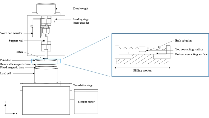
Figure 1: Schematic of two-axis custom friction testing device (left) and cross-section of loaded sample in Petri dish (right). The stage is attached to a motor which induces sliding motion and causes the bottom contacting surface to articulate against the top contacting surface. The load cell collects real-time load measurements, while the loading stage linear encoder collects real-time creep displacement measurements. The figure has been modified with permission from Reference10. Please click here to view a larger version of this figure.
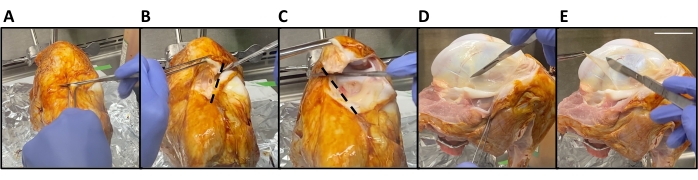
Figure 2: Bovine synovium harvest. (A) The patellar tendon is severed using a horizontal incision superior to the tibia. (B,C) The patella is removed by making two anterior-to-posterior cuts in the shape of a V (dotted lines). (D) The outline of the synovium is traced with a scalpel blade. (E) The synovium is then stretched distal to the underlying bone and removed. Scale bar = 5 cm. Please click here to view a larger version of this figure.

Figure 3: Bovine femoral cartilage plug harvest. (A) A 15.9 mm diameter biopsy punch is inserted normal to the femoral condyle articular cartilage surface until the bone is reached. (B) The punch and plug are removed. Scale bar = 16 mm. Please click here to view a larger version of this figure.

Figure 4: Bovine cartilage tibial strip harvest. (A) The meniscus is removed from the tibial plateau. (B) The plateau edges are cut to make straight sides (inset). (C) The inside of the plateau is scored to create a strip. (D) A cut is made at the cartilage-bone interface. (E) A screwdriver is inserted below the cut. (F) The strip is removed. Scale bar = 10 mm. Please click here to view a larger version of this figure.

Figure 5: LabVIEW user interface. The custom program allows for controlling various test parameters such as stage acceleration, stage speed, travel path, and test duration. (A) Real-time applied load plot (Fz vs. t where Fz is the normal load Fn), (B) stepper position (ux vs. t), and (C) hysteresis plot (Fx vs. ux, where Fx is the tangential force Ft) are shown. Please click here to view a larger version of this figure.

Figure 6: Synovium-on-cartilage friction measurements. (A) The friction testing device configured for juvenile bovine synovium (inset) on a tibial cartilage strip. (B) Representative friction coefficient (μ) as a function of time plot. (C) The friction coefficient for various contact stresses (180 kPa, blue; 230 kPa, red; 300 kPa, green) in a phosphate-buffered saline (PBS, closed circle) or bovine synovial fluid (SF, open circle) bath. Error bars are mean with standard deviation. Please click here to view a larger version of this figure.
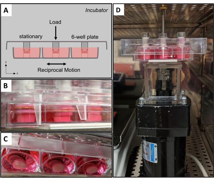
Figure 7: Friction bioreactor. (A) Schematic of friction bioreactor with stationary top counterfaces and moving bottom counterfaces. (B) A side-view and (C) bottom view of the bioreactor applying physiologic shear in a synovium-on-cartilage configuration. (D) The bioreactor is housed inside of a tissue culture incubator. Please click here to view a larger version of this figure.
Supplemental Coding Files. Please click here to download this file.
Subscription Required. Please recommend JoVE to your librarian.
Discussion
A dynamic mechanical environment exists within the joint as cartilage is subjected to compressive, tensile, and shear forces, and hydrostatic and osmotic pressures44,45. Although cartilage is the main load-bearing tissue of the joint, the synovium also undergoes frictional interactions with the cartilage surface and with itself in regions where the tissue folds. The physical interactions between cartilage and synovium are likely responsible for transferring cells and releasing mesenchymal stem cells into the joint environment, offering a potential cell source to contribute to (limited) articular cartilage repair mechanisms37,38,39,40. The frictional properties of both cartilage and synovium have important implications for joint maintenance and degeneration through tissue wear13. A device capable of delivering reciprocal translating motion and compressive loading is presented to study the mechanical and mechanobiological processes responsible for joint homeostasis and disease progression.
The selection of testing parameters and specimen mounting are two critical steps of the protocol. The device applies a compressive load with either dead weights or a voice coil actuator. The custom software program allows for control over various parameters such as test duration, stage speed, and travel path. An issue may arise if the test duration is too short; when this is the case, the short duration does not allow the friction coefficient μ to reach equilibrium (μeq). If the μeq output is desired, the user must select an appropriate test duration that will be able to capture the tissue behavior until it becomes constant. Samples can reach equilibrium within a few hours of testing, depending on the size of the contact area on the tissue46. The type of test must also be considered. The device has been used in the stationary contact area and migrating contact area configurations to study cartilage friction properties5,6,9,11,12,47. The travel path, stage speed, and congruence of the two counterfaces can be manipulated to produce the desired testing mode. It is recommended to create real-time plots in the LabVIEW program user interface to assist in monitoring a test. Helpful plots include horizontal stage position vs. time, normal force vs. time, and tangential force vs. horizontal stage position (hysteresis, Figure 5C). For example, the top counterface must only rest on the bottom counterface to ensure the full prescribed load is applied. The applied load value can be confirmed by viewing the normal load real-time plot (Figure 5A). The mounting of specimens must be secure to prevent tissue slipping or tearing that will provide erroneous measurements. Synovium tearing due to improper mounting will result in an incorrect friction coefficient, as the mounting surface underneath the synovium will be exposed. This error may be detected by monitoring real-time hysteresis curves. The device's real-time assessment of functional properties is distinct from other friction testing systems.
All raw data needs to be written to a file that can be imported and processed by the desired data processing software. It is recommended to collect data at a frequency of at least 10 data points/second and to save raw data to a .csv or .txt file. The friction coefficient can be calculated for each position in each cycle by using the equation  where t and n refer to the tangential and normal forces, respectively, and where + and - refer to the forward and backward strokes, respectively, per cycle5. This formula recognizes that the sign of F-t is opposite to that of F+t. Normal force (Fn) is defined as the force in line with the applied load (z-direction, Figure 1), while tangential force (Ft) is the force parallel with sliding (x-direction, Figure 1). The cycle-average friction coefficient can be calculated by taking the mean of μ for all positions in a given cycle. The creep displacement is calculated by normalizing the vertical displacement of the top counterface such that the initial displacement is zero and the subsequent displacements are relative to the initial displacement. If desired, standard tissue assessments and media analyses can be performed on the tested explants and aliquots of the testing bath solution. Prior to analysis, it is recommended to record the testing bath volume to be used in data processing or normalization.
The modular counterfaces have enabled the adaptation of multiple testing configurations. Early studies used glass-on-cartilage testing to elucidate the role of interstitial fluid load support in cartilage tribology9,10. The importance of interstitial fluid pressurization was further validated by comparing stationary and migrating contact area tests for cartilage-on-cartilage and cartilage against glass11. Oungoulian et al.6 evaluated the wear mechanism of articular cartilage against metal alloys used in hemiarthroplasties and showed that the stresses generated by sliding contact for 4 h facilitated delamination wear through subsurface fatigue failure. This work was followed by Durney et al.5, who demonstrated that delamination wear can still occur when friction remains low under a migrating contact area configuration. Most recently, Estell et al.13 reported for the first time the friction properties of the synovium in testing conditions that mimicked native interactions with underlying tissues (cartilage and synovium) and in conditions that mimicked an osteoarthritic state (diluted synovial fluid bath with cartilage wear particles). Ultimately, the design flexibility of the friction testing device has permitted a wide range of experiments to be conducted, contributing to the greater understanding of cartilage and synovium tribology.
One limitation of the current system is that it can only maintain aseptic testing conditions for a few hours. This is achieved through the acrylic enclosure, sterilizing media-contacting components via autoclave, and spraying the testing device with 70% ethanol. The acrylic enclosure also includes a heating element and constant temperature monitoring capabilities. The heating element heats the air within the box, controlling the temperature of the inside environment, and can be controlled externally to avoid exposing the samples to the outside environment. Aseptic conditions can be further achieved by harvesting the specimens in a sterile biological safety cabinet (BSC) and assembling the specimens inside the BSC within a sterile container that can interface with the support rod and fixed base. For long-term studies, the acrylic enclosure can be outfitted with the necessary materials to provide a more sterile environment (ultraviolet light, proper airflow and filtration, and self-regulating temperature control). Another limitation is that the current friction testing device is configured to test a single top and bottom counterface. A multi-specimen counterface approach can be attained by altering the loading platen and removable base design, converting the current friction testing device to a bioreactor with a multi-well capacity to apply physiologic loading of cartilage-on-cartilage and synovium-on-cartilage. A working prototype using a 6-well plate has been created (Figure 7). The design reserves the ability to modulate top and bottom counterfaces as desired. The top of the plate is stationary and secured to a tissue culture incubator rack, while the bottom of the plate is attached to a translating stage. Similar to the current friction testing device, dead weight can be added to prescribe a normal load. With the bioreactor in a sterile environment, media can be sampled over time to evaluate biological responses to loading regimens. The next design iteration will look to create a stand-alone bioreactor that incorporates computer-controlled translation. If the complexity of the friction testing device were to be maintained in the bioreactor, changes to tissue mechanical and mechanobiological properties could be measured longitudinally.
A friction testing device that permits control over the delivery of reciprocal translating motion and normal load to two contacting biological counterfaces is described. In this study, a synovium-on-cartilage configuration was utilized to demonstrate the modularity of the device and the ability to study the frictional responses of living tissues. The representative results reaffirmed the role of synovial fluid in providing boundary lubrication to reduce wear and friction of the diarthrodial joint. The device permits the execution of multi-scale experiments ranging from bulk friction to mechanotransduction. The design can operate under sterile conditions for a few hours and can be converted to a long-term bioreactor to recapitulate the compressive sliding of the joint, thereby facilitating the study of biomechanics, mechanobiology, and physical regulation of living joint tissues. Future studies will contribute to understanding how healthy and diseased physical environments influence joint maintenance.
Subscription Required. Please recommend JoVE to your librarian.
Disclosures
The authors have nothing to disclose.
Acknowledgments
This work was supported by the Orthopaedic Scientific Research Foundation, NIH 5R01 AR068133, NIH TERC 5P41EB027062, and NIGMS R01 692 GM083925 (Funder ID: 10.13039/100000057).
Materials
| Name | Company | Catalog Number | Comments |
| Aluminum foil | Reynolds Group Holdings | Reynolds Wrap | Sterile tissue harvest |
| Aluminum-framed acrylic enclosure | Custom made | Friction tester component | |
| Autoclavable instant sealing sterilization pouches | Fisherbrand | 01-812-54 | Sterilization of tools |
| Autoclave | Buxton | Sterilization of tools | |
| Beaker (250 mL) | Pyrex Vista | 70000 | Tissue harvest |
| Betadine (Povidone Iodine Prep Solution) | Medline Industries, LP | MDS093906 | Sterile tissue harvest |
| Biological safety cabinet | Labconco | Purifier Logic+ Class II, Type A2 BSC | Sterile tissue harvest |
| Biospy punch | Steritool Inc. | 50162 | Tissue harvest |
| Box cutter | American Safety Razor Company | 94-120-71 | Tissue harvest |
| Circular acrylic-sillicone post (synovium) | Custom made | Tissue mounting | |
| Culture media | Custom made | DMEM (Cat No. 11-965-118; Gibco) supplemented with 50 μg/mL L-proline (Cat. No. P5607; Sigma), 100 μg/mL sodium pyruvate (Cat. No. S8636; Sigma), 1% ITS (Cat. No. 354350; Corning), and 1% antibiotic–antimycotic (Cat. No. 15-240-062, Gibco) | |
| Cyanoacrylate (Loctite 420 Clear) | Henkel | 135455 | Tissue mounting |
| Dead weights | OHAUS | Normal load | |
| Ethanol 200 proof | Decon Labs, Inc. | 2701 | Dilute to 70 % |
| Fixed base | ThorLabs, Inc. | SB1T | Friction tester component |
| Forceps (synovium harvest) | Fine Science Tools | 11019-12 | Tissue harvest |
| Forceps (synovium mounting) | Excelta | 3C-S-PI | Tissue mounting |
| Horizontal linear encoder (for translating stage) | RSF Electronics, Inc. | MSA 670.63 | Friction tester component; system resolution of 1 µm |
| Hot glue gun and glue | FPC Corporation | Surebonder Pro 4000A | Tissue mounting |
| LabVIEW | National Instruments Corporation | LabVIEW 2010 | Friction testing program |
| Load cell | JR3 Inc. | 20E12A-M25B | Friction tester component; 0.0019 lbs resolution in x&y, 0.0038 lbs resolution in z |
| Loading platen | Custom made | Tissue mounting | |
| O-ring | Parker | S1138AS568-009 | Tissue mounting |
| Petri dish (60 mm) | Falcon | 351007 | Tissue mounting |
| PivotLok Work Positioner (tibia holder) | Industry Depot, Pivot Lok | PL325 | Tissue harvest |
| Removable base | ThorLabs, Inc. | SB1B | Friction tester component |
| Ring stand | Tissue harvest | ||
| Scalpel blades | Havel's Inc. | FSC22 | Tissue harvest |
| Scalpel handle | FEATHER Safety Razor Co., Ltd. | No. 4 | Tissue harvest |
| Screwdriver | Wera | 3334 | Tissue harvest |
| Stage | JMAR | Friction tester component | |
| Stepper motor | Oriental Motor Co., Ltd. | PK266-03B | Friction tester component |
| Suction tool | Virtual Industries, Inc. | PEN-VAC Vacuum Pen | Tissue mounting |
| Support rod | Custom made | Tissue mounting | |
| Surgical scissors | Fine Science Tools | 14061-09 | Tissue mounting |
| Synovial fluid (bovine) | Animal Technologies, Inc. | Friction testing bath | |
| Testing bath | Custom made | Phosphate-Buffered Saline (PBS) with protease inhibitors: 0.04% isothiazolone-base biocide (Proclin 950 Cat. No. 46878-U; Sigma) and 0.1% protease inhibitor - 0.05 M ethylenediaminetetraacetic acid, EDTA (Cat. No. 0369; Sigma) | |
| Tissue culture incubator | Fisher Scientific | Isotemp | Sterile culture |
| Vertical linear encoder (for loading stage) | Renishaw | T1031-30A | Friction tester component; 20 nm resolution |
| Voice coil actuator | H2W Technologies | NCC20-15-027-1RC | Friction tester component |
References
- US Department of Health and Human Services. The Cost of Arthritis in US Adults. Centers for Disease Control and Prevention. , Available from: https://www.cdc.gov/arthritis/data_statistics/cost.htm (2020).
- Buckwalter, J. A., Mankin, H. J. Instructional course lectures, the American academy of orthopaedic surgeons - articular cartilage. Part II: degeneration and osteoarthrosis, repair, regeneration, and transplantation. JBJS. 79 (4), 612-632 (1997).
- Berenbaum, F. Osteoarthritis as an inflammatory disease (osteoarthritis is not osteoarthrosis). Osteoarthritis and Cartilage. 21 (1), 16-21 (2013).
- Sellam, J., Berenbaum, F. The role of synovitis in pathophysiology and clinical symptoms of osteoarthritis. Nature Reviews Rheumatology. 6 (11), 625-635 (2010).
- Durney, K. M., et al. Immature bovine cartilage wear by fatigue failure and delamination. Journal of Biomechanics. 107, 109852 (2020).
- Oungoulian, S. R., et al. Wear and damage of articular cartilage with friction against orthopedic implant materials. Journal of Biomechanics. 48 (10), 1957-1964 (2015).
- Ateshian, G. A. The role of interstitial fluid pressurization in articular cartilage lubrication. Journal of Biomechanics. 42 (9), 1163-1176 (2009).
- Sophia Fox, A. J., Bedi, A., Rodeo, S. A. The basic science of articular cartilage. Sports Health. 1 (6), 461-468 (2009).
- Krishnan, R., Kopacz, M., Ateshian, G. A. Experimental verification of the role of interstitial fluid pressurization in cartilage lubrication. Journal of Orthopaedic Research. 22 (3), 565-570 (2004).
- Krishnan, R., et al. Removal of the superficial zone of bovine articular cartilage does not increase its frictional coefficient. Osteoarthritis and Cartilage. 12 (12), 947-955 (2004).
- Caligaris, M., Ateshian, G. A. Effects of sustained interstitial fluid pressurization under migrating contact area, and boundary lubrication by synovial fluid, on cartilage friction. Osteoarthritis and Cartilage. 16 (10), 1220-1227 (2008).
- Caligaris, M., Canal, C. E., Ahmad, C. S., Gardner, T. R., Ateshian, G. A. Investigation of the frictional response of osteoarthritic human tibiofemoral joints and the potential beneficial tribological effect of healthy synovial fluid. Osteoarthritis and Cartilage. 17 (10), 1327-1332 (2009).
- Estell, E. G., et al. Attachment of cartilage wear particles to the synovium negatively impacts friction properties. Journal of Biomechanics. 127, 110668 (2021).
- Ateshian, G. A., Mow, V. C. Friction, lubrication, and wear of articular cartilage and diarthrodial joints. Basic Orthopaedic Biomechanics and Mechano-Biology. 3, 447-494 (2005).
- Bonnevie, E. D., Bonassar, L. J. A century of cartilage tribology research is informing lubrication therapies. Journal of Biomechanical Engineering. 142 (3), 031004 (2020).
- Unsworth, A., Dowson, D., Wright, V. Some new evidence on human joint lubrication. Annals of the Rheumatic Diseases. 34 (4), 277-285 (1975).
- Unsworth, A., Dowson, D., Wright, V. The frictional behavior of human synovial joints-part I: natural joints. Journal of Lubrication Technology. 97 (3), 369-376 (1975).
- Shirley Jones, E. Joint Lubrication. The Lancet. 227 (5879), 1043-1045 (1936).
- Ateshian, G. A., et al. The role of osmotic pressure and tension-compression nonlinearity in the frictional response of articular cartilage. Transport in Porous Media. 50 (1), 5-33 (2003).
- Forster, H., Fisher, J. The influence of loading time and lubricant on the friction of articular cartilage. Proceedings of the Institution of Mechanical Engineers, Part H: Journal of Engineering in Medicine. 210 (2), 109-119 (1996).
- McCutchen, C. W. The frictional properties of animal joints. Wear. 5 (1), 1-17 (1962).
- Pickard, J., Ingham, E., Egan, J., Fisher, J. Investigation into the effect of proteoglycan molecules on the tribological properties of cartilage joint tissues. Proceedings of the Institution of Mechanical Engineers, Part H: Journal of Engineering in Medicine. 212 (3), 177-182 (1998).
- Wang, H., Ateshian, G. A. The normal stress effect and equilibrium friction coefficient of articular cartilage under steady frictional shear. Journal of Biomechanics. 30 (8), 771-776 (1997).
- Walker, P. S., Dowson, D., Longfield, M. D., Wright, V. Boosted lubrication in synovial joints by fluid entrapment and enrichment. Annals of the Rheumatic Diseases. 27 (6), 512-520 (1968).
- Walker, P. S., Unsworth, A., Dowson, D., Sikorski, J., Wright, V. Mode of aggregation of hyaluronic acid protein complex on the surface of articular cartilage. Annals of the Rheumatic Diseases. 29 (6), 591-602 (1970).
- Gleghorn, J. P., Bonassar, L. J. Lubrication mode analysis of articular cartilage using Stribeck surfaces. Journal of Biomechanics. 41 (9), 1910-1918 (2008).
- Malcom, L. An experimental investigation of the frictional and deformational responses of articular cartilage interfaces to static and dynamic loading. , dissertation (1976).
- Schmidt, T. A., Sah, R. L. Effect of synovial fluid on boundary lubrication of articular cartilage. Osteoarthritis and Cartilage. 15 (1), 35-47 (2007).
- Ateshian, G. A., Wang, H. Rolling resistance of articular cartilage due to interstitial fluid flow. Proceedings of the Institution of Mechanical Engineers, Part H: Journal of Engineering in Medicine. 211 (5), 419-424 (1997).
- Oungoulian, S. R., et al. Articular cartilage wear characterization with a particle sizing and counting analyzer. Journal of Biomechanical Engineering. 135 (2), 0245011-0245014 (2013).
- Radin, E. L., Paul, I. L., Swann, D. A., Schottstaedt, E. S. Lubrication of synovial membrane. Annals of the Rheumatic Diseases. 30 (3), 322-325 (1971).
- Estell, E. G., et al. Fibroblast-like synoviocyte mechanosensitivity to fluid shear is modulated by Interleukin-1α. Journal of Biomechanics. 60, 91-99 (2017).
- Momberger, T. S., Levick, J. R., Mason, R. M. Hyaluronan secretion by synoviocytes is mechanosensitive. Matrix Biology: Journal of the International Society for Matrix Biology. 24 (8), 510-519 (2005).
- Momberger, T. S., Levick, J. R., Mason, R. M. Mechanosensitive synoviocytes: A Ca2+-PKCα-MAP kinase pathway contributes to stretch-induced hyaluronan synthesis in vitro. Matrix Biology. 25 (5), 306-316 (2006).
- Yanagida-Suekawa, T., et al. Synthesis of hyaluronan and superficial zone protein in synovial membrane cells modulated by fluid flow. European Journal of Oral Sciences. 121 (6), 566-572 (2013).
- Cooke, A. F., Dowson, D., Wright, V. Lubrication of synovial membrane. Annals of the Rheumatic Diseases. 35 (1), 56-59 (1976).
- Goldring, M. B., Berenbaum, F. Emerging targets in osteoarthritis therapy. Current Opinion in Pharmacology. 22, 51-63 (2015).
- Jones, E. A., et al. Synovial fluid mesenchymal stem cells in health and early osteoarthritis: Detection and functional evaluation at the single-cell level. Arthritis and Rheumatism. 58 (6), 1731-1740 (2008).
- Sampat, S. R., et al. Growth factor priming of synovium-derived stem cells for cartilage tissue engineering. Tissue Engineering. Part A. 17 (17-18), 2259-2265 (2011).
- Kurth, T. B., et al. Functional mesenchymal stem cell niches in adult mouse knee joint synovium in vivo. Arthritis and Rheumatism. 63 (5), 1289-1300 (2011).
- Krishnan, R., Mariner, E. N., Ateshian, G. A. Effect of dynamic loading on the frictional response of bovine articular cartilage. Journal of Biomechanics. 38 (8), 1665-1673 (2005).
- Bonnevie, E. D., Baro, V., Wang, L., Burris, D. L. In-situ studies of cartilage microtribology: roles of speed and contact area. Tribology Letters. 41 (1), 83-95 (2011).
- Bian, L., et al. Dynamic mechanical loading enhances functional properties of tissue-engineered cartilage using mature canine chondrocytes. Tissue Engineering. Part A. 16 (5), 1781-1790 (2010).
- Mow, V. C., Wang, C. C., Hung, C. T. The extracellular matrix, interstitial fluid and ions as a mechanical signal transducer in articular cartilage. Osteoarthritis and Cartilage. 7 (1), 41-58 (1999).
- Wang, C. C. -B., et al. The functional environment of chondrocytes within cartilage subjected to compressive loading: a theoretical and experimental approach. Biorheology. 39 (1-2), 11-25 (2002).
- Carter, M. J., Basalo, I. M., Ateshian, G. A. The temporal response of the friction coefficient of articular cartilage depends on the contact area. Journal of Biomechanics. 40 (14), 3257-3260 (2007).
- Jones, B. K., Durney, K. M., Hung, C. T., Ateshian, G. A. The friction coefficient of shoulder joints remains remarkably low over 24 h of loading. Journal of Biomechanics. 48 (14), 3945-3949 (2015).
