This paper presents a method to construct and operate a low-cost, multichannel perfusion cell culture system for measuring the dynamics of secretion and absorption rates of solutes in cellular processes. The system can also expose cells to dynamic stimulus profiles.
Method Article
Multi-Stream Perfusion Bioreactor Integrated with Outlet Fractionation for Dynamic Cell Culture
In This Article
Summary
Loading...
Abstract
Loading...
Introduction
Loading...

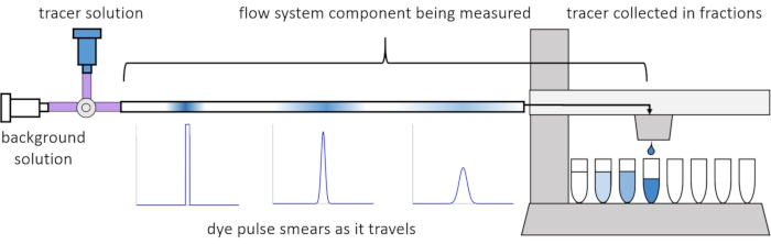
Access restricted. Please log in or start a trial to view this content.
Protocol
Loading...
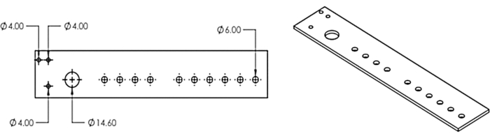
Access restricted. Please log in or start a trial to view this content.
Results
Loading...
Access restricted. Please log in or start a trial to view this content.
Discussion
Loading...
Access restricted. Please log in or start a trial to view this content.
Disclosures
Loading...
Acknowledgements
Loading...
Access restricted. Please log in or start a trial to view this content.
Materials
| Name | Company | Catalog Number | Comments |
|---|---|---|---|
| 18 Gauge 1 1/2- in Disposable Probe Needle For Use With Syringes and Dispensing Machines | Grainger | 5FVK2 | |
| 293T Cells | ATCC | CRL-3216 | HEK 293T cells used in the Representative Results experiment. |
| 96-Well Clear Bottom Plates, Corning | VWR | 89091-010 | Plates for measuring dye concentrations in RTD experiments and GLuc in representative results experiment. |
| BD Disposable Syringes with Luer-Lok Tips, 5 mL | Fisher Scientific | 14-829-45 | |
| BioFrac Fraction Collector | Bio-Rad | 7410002 | Fraction collector that can be used for a single stream, or modified using our method to enable collection from multiple streams. |
| Clear High-Strength UV-Resistant Acrylic 12" x 12" x 1/8" | McMaster-Carr | 4615T93 | This sheet is cut using a laser cutter according to the DXF file in the supplemental materials to produce the multi-head dispenser that can be attached to the BioFrac fraction collector. |
| Coelenterazine native | NanoLight Technology | 303 | Substrate used in Gaussia luciferase bioluminescence assay in representative results. |
| Corning Costar TC-Treated Multiple Well Plates, size 48 wells, polystyrene plate, flat bottom wells | Millipore Sigma | CLS3548 | Used to grow and perfuse 293T cells in representative results. |
| Corning Costar Flat Bottom Cell Culture Plates, size 12 wells | Fisher Scientific | 720081 | Can be plugged and used as a stirred tank to produce pharmacokinetic profiles in perfusion. Can also contain cells for perfusion. |
| DMEM, high glucose | ThermoFisher Scientific | 11965126 | |
| Epilog Zing 24 Laser | Cutting Edge Systems | Epilog Zing 24 | Laser cutter used to produce multi-head dispenser from acrylic sheet. Other laser cutters may be used. |
| Fisherbrand Sterile Syringes for Single Use, Luer-Lock, 20 mL | Fisher Scientific | 14-955-460 | |
| Fisherbrand Sterile Syringes for Single Use, Luer-Lock, 60 mL | Fisher Scientific | 14-955-461 | |
| Fisherbrand Premium Microcentrifuge Tubes: 1.5mL | Fisher Scientific | 05-408-129 | Microcentrifuge tubes for collecting fractions. |
| Fisherbrand Round Bottom Disposable Borosilicate Glass Tubes with Plain End | Fisher Scientific | 14-961-26 | Glass tubes for collecting fractions. |
| Fisherbrand SureOne Micropoint Pipette Tips, Universal Fit, Non-Filtered | Fisher Scientific | 2707410 | 300 ul pipette tips that best fit the multi-head dispenser and tubing to act as dispensing tips. |
| Gibco DPBS, powder, no calcium, no magnesium | Fisher Scientific | 21600010 | Phosphate buffered saline. |
| Labline 4625 Titer Shaker | Marshall Scientific | Labline 4625 Titer Shaker | Orbital shaker used to keep stirred tanks mixed. |
| Masterflex Fitting, Polycarbonate, Four-Way Stopcock, Male Luer Lock, Non-Sterile; 10/PK | Cole-Parmer | EW-30600-04 | Used to join multiple inlet streams for RTD experiments and cell culture experiments. |
| Masterflex Fitting, Polycarbonate, Straight, Female Luer x Cap; 25/PK | Masterflex | UX-45501-28 | |
| Masterflex Fitting, Polypropylene, Straight, Female Luer to Hosebarb Adapters, 1/16" | Cole-Parmer | EW-45508-00 | |
| Masterflex Fitting, Polypropylene, Straight, Male Luer Lock to Hosebarb Adapter, 1/16" ID | Cole-Parmer | EW-45518-00 | |
| Masterflex Fitting, Polypropylene, Straight, Male Luer Lock to Plug Adapter; 25/PK | Masterflex | EW-30800-30 | |
| Masterflex L/S Precision Pump Tubing, Platinum-Cured Silicone, L/S 14; 25 ft | Masterflex | EW-96410-14 | |
| MATLAB | MathWorks | R2019b | Version R2019b. Newer versions may also be used. Some older versions may work. |
| NE-1600 Six Channel Programmable Syringe Pump | New Era Pump Systems | NE-1600 | |
| Rack Set F1 | Bio-Rad | 7410010 | Racks to hold collecting tubes in the fraction collector. |
| Recombinant Human TNF-alpha (HEK293-expressed) Protein, CF | Bio-Techne | 10291-TA-020 | Cytokine used to stimulate 293T cells in representative results. |
| Saint Gobain Solid Stoppers, Versilic Silicone, Size: 00, Bottom 10.5mm | Saint Gobain | DX263015-50 | Fits 48-well plates. |
| Saint Gobain Solid Stoppers, Versilic Silicone, Size: 4 Bottom 21mm | Saint Gobain | DX263027-10 | Fits 12-well plates. |
| Sodium Hydroxide, 10.0 N Aqueous Solution APHA; 1 L | Spectrum Chemicals | S-395-1LT | |
| SolidWorks | Dassault Systems | SolidWorks | CAD software used to create the multi-head dispenser DXF file. |
| Varioskan LUX multimode microplate reader | ThermoFisher Scientific | VL0000D0 | Plate reader. |
| Wilton Color Right Performance Color System Base Refill, Blue | Michaels | 10404779 | Blue food dye containing Brilliant Blue FCF, used as a tracer in RTD experiments. Absorbance spectrum peaks at 628 nm. |
References
Loading...
Access restricted. Please log in or start a trial to view this content.
Reprints and Permissions
Request permission to reuse the text or figures of this JoVE article
Request Permission