Tissue culture inserts with plastic membranes are the golden standard in cell culture labs as permeable supports to establish cell layers and models of barrier tissues. Herein, we present a simple method to replace the plastic membrane with a more biologically relevant membrane made from a recombinant functionalized spider silk protein.
Method Article
Nanofibrillar Basement Membrane Mimic Made of Recombinant Functionalized Spider Silk in Custom-Made Tissue Culture Inserts
* These authors contributed equally
In This Article
Summary
Abstract
Replicating tissue barriers is critical for generating relevant in vitro models for evaluating novel therapeutics. Today, this is commonly done using tissue culture inserts with a plastic membrane, which generates an apical and a basal side. Besides providing support for the cells, these membranes come far from emulating their native counterpart, the basement membrane, which is a nanofibrillar, protein-based matrix. In this work, we show a simple way to considerably improve the biological relevance of the tissue culture inserts by replacing the plastic membrane with one made from a pure recombinant functionalized spider silk protein. The silk membrane forms through self-assembly and will spontaneously adhere to a membrane-free tissue culture insert, where it can provide support for cells. Custom-designed tissue culture inserts can be printed using a standard 3D printer, following the instructions provided in the protocol, or commercial ones can be purchased and used instead. This protocol shows how the culture system with silk membranes in inserts is set up and, subsequently, how the same cell culturing techniques that are used with traditional, commercially available inserts can be implemented.
Introduction
In vitro models that can replicate tissue barriers have received increasing attention due to their applicability in testing novel therapeutics and facilitating the understanding of fundamental disease mechanisms1,2. To accurately recreate the native microenvironment, it is critical to recapitulate the function of the basement membrane (BM), a highly specialized extracellular matrix (ECM) complex. The BM exists in almost every tissue in the human body, where it provides support to endothelial and epithelial cells and separates them from underlying tissue2,3. Beyond providing physical support, the BM also regulates and maintains biochemical signals between the cells and surrounding tissue. These vital functions make it necessary to design scaffolds that resemble the structure, as well as the mechanical and functional characteristics of the native BM3.
One of the most common ways to mimic the BM in vitro today is through the use of commercially available tissue culture inserts (TC-inserts). These are essentially plastic cylinders with a permeable membrane that divides the chamber into apical and basolateral sides4,5. While easy to use, the membranes in commercial inserts are generally rigid, track-etched, and made from polymers such as poly(carbonate) (PC) and poly(ethylene terephthalate) (PET)3,4,6. They are flexible in terms of diameter, pore density, and size and can be coated to enhance cell adhesion but lack all other relevant features of the BM, such as comparable thickness6, interconnected porosity, fibrous architecture, and relevant elastic modulus3.
The standardization of TC inserts and their ease of use has inspired several groups, including ours, to replace the plastic membrane with a more in vivo-like counterpart (overviewed in Table 1). The materials used range from polymers such as Polydimethylsiloxane (PDMS)7, Poly(lactide-co-caprolactone) (PLCL)8, and polycaprolactone (PCL)4,9,10 to protein-based materials such as gelatin2,11,12, collagen5,13, and recombinant spider silk14,15,16,17. Membranes from these materials have been attached in various ways, both to commercially available inserts from which the membrane has been removed4,7,8,10,12,13,14,16,18,19,20,21, as well as to custom-designed inserts manufactured through 3D-printing1,11,15,17,20 or injection molding9,22. However, most of these still come far from resembling the native BM in terms of thickness, where the replicas range from hundreds11,18 down to a few micrometers5,10,14,21,22. Many of them also require complex formation and/or manual attachment methods1,7,13,14,18,19,21, making scaling and replication in other labs challenging.
Herein, we present a simple method to form and attach a silk membrane to inserts and show how to culture cells on either side of the membrane. The silk membranes are formed through self-assembly of the FN-4RepCT (FN-silk) protein at the liquid-air interface of a standing solution16,17. FN-silk is a recombinantly produced short version of Major Ampullulate Spidroin 1 from Euprosthenops australis, functionalized with an RGD motif derived from fibronectin23. It has been shown to assemble into fibrillar matrices that promote cell adhesion, growth, and migration15,16,17,23,24,25. The method for attachment of the membrane on the insert relies on spontaneous adhesion and has been found suitable for commercially available inserts from which the membrane has been removed16, as well as 3D-printed inserts from polylactic acid (PLA)17 and Dental LT15. This paper details how this method is used for inserts printed from Dental LT. After the FN-silk membranes have been attached to the inserts, they can, in essence, be treated like standard commercial tissue culture inserts. In short, we present a simple method to generate more relevant in vitro models of tissue barriers by replacing plastic membranes with a protein-based, FN-silk membrane.
Protocol
1. 3D-printing of inserts
- Download the .STL design file (JoVe_Silk_Insert.stl) from Supplemental File 1.
- Prepare the files for printing by opening them in the software package dedicated to converting a .STL file to a print file for the 3D-printer being used.
- Use the dedicated software to add supports. The supporting structure is designed by the software, and the amount needed will depend on the printer and the software being used. Orient the insert so that neither the building platform nor the supports touch the bottom.
- Print the desired number of inserts using a biocompatible resin (such as Dental LT or BioMed) or filament (such as PLA) suitable for the 3D printer being used.
NOTE: Make sure that the material can withstand a suitable sterilization process such as autoclaving, irradiation, or ethanol submersion. - Detach the printed inserts from the printing platform and remove the printed supporting structure from the finished part.
- If using a resin printer, process the inserts using the standard protocol provided by the manufacturer.
NOTE: Processing might vary depending on which resin is used. The protocol used for the resin used herein is provided in Supplemental File 2. - Sterilize the inserts using a technique suitable for the material of choice.
NOTE: Recommendations are autoclaving, irradiation, or submersion in 70% ethanol, or a combination thereof. If using a resin printer, an extensive leaching out protocol might be needed to achieve optimal biocompatibility. Refer to the protocol provided in Supplemental File 2 for a recommendation. - Make sure that the inserts are completely dry and store them sterile until use.
2. Formation of FN-silk membranes
- Fill a box with dry ice and bring it to the -80 °C freezer.
- Collect the FN-silk vials from the -80 °C freezer and place them in dry ice for transportation. Bring the FN-silk vials to a biological safety cabinet and perform further steps there. Place the FN-silk vials in a microcentrifuge tube rack to thaw without touching them excessively.
- While the FN-silk is thawing, unpack the 48-well plate. Once the FN-silk has thawed completely, proceed to the next step within 10 min, preferably as sooner.
- Dilute the FN-silk solution in chilled or room temperature PBS to the desired concentration, preferably 1.8 mg/mL. Pipette 550 µL of FN-silk solution directly into the bottom of an empty well in the 48-well plate. Pipette the FN-silk solution until the desired number of membranes has been prepared.
NOTE: Avoid introducing air bubbles and remove any air bubbles immediately with a pipette. Do not use wells in Row A or F or column 1 or 8, nor adjacent wells (see schematic in Supplemental Figure S1). - Place the lid on the 48-well plate and place it inside a larger, sterile box to provide a sterile environment during the incubation.
- Carefully move the box from the biological safety cabinet and leave it in ambient conditions in an undisturbed place without significant airflow overnight.
3. Adhering FN-silk membranes to inserts
- The next day, bring the sterile inserts to the biological safety cabinet.
- Bring the large sterile box containing the 48-well plate with the FN-silk membranes back into the biological safety cabinet and perform further steps there. Carefully lift the 48-well plate from the large sterile box.
- Visually verify membrane formation by observing cloudiness in the wells and open the lid of the 48-well plate containing the membranes. Pick up one insert using sterile tweezers and guide the insert down onto the membrane until the handles of the insert touch the top of the well as shown in Figure 1. Keep the bottom of the insert parallel to the bottom of the plate.
- Repeat step 3.3 until inserts have been lowered onto all the formed membranes. Place the lid on top of the 48-well plate and then put the plate back in the sterile box. Leave the plate undisturbed for 2 h at ambient conditions to allow the membranes to adhere to the inserts.
- Prewarm the growth medium or PBS at 37 °C.
- Unpack a 24-well plate.
- Once 2 h have passed, remove the 48-well plate from the box and open the lid. Using sterile tweezers, hold an insert by its handles and lift it out of the 48-well plate.
- Directly after lifting, fill the insert with prewarmed culture medium or PBS. Use 100 µL of culture medium if proceeding with basal side seeding or 200 µL if proceeding with apical side seeding. If the membranes are to be stored for later use, use 200 µL of PBS instead.
CHECKPOINT: If the liquid is retained above the membrane, lifting was successful. If liquid drips onto the bench, the membrane leaks and should be disregarded. - Place the insert in an empty well of the 24-well plate.
- Lift all inserts out of the 48-well plate and transfer them to the 24-well plate. Fill the wells with 1,000 µL of growth medium if proceeding with cell seeding or PBS for storage while keeping the plate slightly tilted.
NOTE: It is important that the edge of the membrane is below the liquid level (Figure 2). - If cells are to be seeded right away, proceed to section 4 or 5 depending on which side of the membrane the cells are to be seeded. If not, place the lid on the 24-well plate and place it either in the fridge (4 °C) or in a 37 °C incubator. If placed in the incubator, replenish the PBS every second day to ensure that the needed volume is maintained.
4. Cell seeding on the apical side of the membrane
NOTE: If the membranes have been stored in PBS, replace the PBS with prewarmed culture medium as described in section 6.
- Harvest the cells. Prepare the cell suspension such that the desired number of cells per membrane is present in 20-50 µL of the suspension. Resuspend to achieve the desired cell concentration.
- Using a P100 or P200 pipette, aspirate 20-50 µL of the cell suspension. Aiming the pipette tip towards the center of the membrane, keep the tip 1-2 mm away from the culture medium surface inside the insert and slowly press the pipette plunger to create a droplet at the edge of the tip. Bring the droplet into contact with the culture medium inside the insert.
NOTE: Keep the pipette perpendicular to the working surface. - Repeat step 4.2 for the remaining membranes. Resuspend the cell stock after seeding five membranes to ensure homogeneous cell distribution. Move the plate in a figure-eight pattern to ensure better cell distribution on the membrane.
- Culture under standard conditions (37 °C and 5% CO2) and change medium every second day.
5. Cell seeding on the basal side of the membrane
NOTE: If the membranes have been stored in PBS, replace the PBS with 100 µL of prewarmed growth medium and fill the wells with 1 mL of prewarmed growth medium as described in section 6.
- Harvest the cells and prepare the cell suspension such that the desired number of cells per membrane is present in 20 µL of the suspension. Resuspend to achieve the desired cell concentration.
- Unpack and open the lid of a Petri dish. Ensure that the height of the Petri dish is enough to accommodate the inserts without their bottoms touching the lid.
- Using tweezers, lift the insert out of the 24-well plate, leaving the culture medium in the wells. Using a set of tweezers in each hand, invert the insert so that the basal side faces upwards, and the apical side faces the working area. Place the inverted insert in the Petri dish as in Figure 3C. Repeat for the remaining inserts.
NOTE: Do not remove the culture medium on the apical side. It will keep the membrane wet during the incubation. - Resuspend the cell stock to ensure even cell distribution in the solution, and aspirate 20 µL of the cell suspension with a P100 or P200 pipette. Aiming the pipette tip towards the center of the membrane, keep the tip 1-2 mm away from the membrane and slowly press the pipette plunger to create a droplet at the edge of the tip. Keep the pipette perpendicular to the membrane surface and allow the droplet to fall onto the membrane. Repeat for the remaining membranes.
NOTE: Resuspend the cell stock after seeding five membranes to ensure even cell distribution. - Place the lid on the Petri dish, bring the Petri dish and the 24-well plate to the incubator, and incubate the inserts with the cells under standard conditions (37 °C and 5 % CO2) for 30 min.
- Bring the 24-well plate containing culture medium and the Petri dish into the biologically safety cabinet. Open both lids and using a set of tweezers in each hand, pick up one insert and invert it so that the apical side of the membrane now faces upwards and the basal side downwards.
- Using a P200 pipette, add 200 µL of culture medium inside the insert. Place the insert into one of the prefilled wells of the 24-well plate and repeat for the remaining membranes.
- Culture under standard conditions (37 °C and 5% CO2) and change medium every second day.
6. Medium change of cultures in submerged conditions
- Prepare a new 24-well plate with the fresh culture medium by adding 1,000 µL/well. Using tweezers, lift one insert out of the 24-well plate, slightly tilt it, and remove the medium from the apical side.
- Add 200 µL of fresh culture medium inside the insert. Place the insert into a well that is prefilled with fresh culture medium. Repeat for all the membranes.
7. Medium change of cultures in airlift conditions
- Using tweezers, lift the insert and place it into an empty well of a 24-well plate. Repeat for four more membranes.
- Slightly tilt the 24-well plate and slowly add 1,000 µL of fresh culture medium inside each plate well. Repeat for the remaining membranes.
8. Measuring transepithelial electrical resistance (TEER)
- Prepare a 24-well plate with 1,000 µL of culture medium or PBS inside the wells and transfer the membranes into it. Make sure to have 200 µL of the corresponding solution above the membrane.
- Using a set of tweezers, stabilize the insert inside the plate well by gently pressing on the insert arms. Without removing the tweezers, insert the TEER electrode into the well and record the measurement.
- Remove the electrode and then lift the tweezers.
- Repeat steps 8.2-8.3 for the remaining membranes.
Results
Representative photographs of the inserts
Photographs of the inserts before and after release from the print platform are shown in Figure 3A,B. An image of a finished insert from which the support has been removed is shown in Figure 3C. The result is a batch of 3D-printed inserts, ready for sterilization and subsequent use.
Lifting and handling of FN-silk membranes
A general schematic of the FN-silk membrane formation and manual lifting is shown in Figure 1. The result is a number of inserts with an FN-silk membrane attached. To ensure the highest success rate with lifting intact membranes, the steps outlined in the protocol should be followed precisely. Figure 4 shows photographs of a membrane while intact (A,D) and after tearing (B,E,F). The tear can be visualized with the use of brightfield microscopy (Figure 4E,F) and/or by the dripping of liquid through the membrane (Figure 4B). It is important to lift and lower the inserts perpendicular to the membrane, to ensure that the membrane adheres evenly and stretches below the inserts. Membrane adhesion can be visually observed, as shown in Figure 4A. If the insert is lowered as instructed and the liquid levels are kept as shown in Figure 2, the membrane remains attached to the insert throughout long culture periods.
Herein, membrane attachment to the insert is validated by conducting a permeation experiment15,16,17 on membranes that had been kept under standard cell culture conditions for 9 days. Briefly, when adding a fluorescent molecule on top of the membrane and measuring the signal in the solution below, the permeation profile of the silk membranes follows that of a commercially available tissue culture insert (Figure 4C), showing no leakage over 36 h of permeation and indicating that the membrane remains both intact and attached to the insert. Similar experiments have previously been conducted with cells seeded on one15 or both sides of the silk membrane17. The strength of the adhesion has previously been shown using macro indentation16 and inflation tests16,17. Within the macro indentation experiments, a stylus was used to stretch the membrane, which ruptured under a force of 1.4 mN, while remaining attached to the insert16.
It should be noted that the success rate of lifting intact membranes is related to the material and posttreatment of the inserts. With this protocol, 95% of the membranes lifted using inserts printed with the resin used were appropriate for cell seeding, compared to 74% when a comparable resin was used instead. We speculate that the adhesion is aided by hydrophobic interactions and van der Waals forces, and thus altering the material properties changes the strength of the adhesion. This is further supported by the fact that the membranes do not adhere well to hydrophilic materials (data not shown).
Representative results of cell culture on the FN-silk membranes
Immunofluorescence images of keratinocytes (HaCaT) cultured on the apical or basal side of the membrane are shown in Figure 5. The adhered cells (Figure 5D.i) were observed to evenly cover the culture area on Day 1 while acquiring the typical keratinocyte cobblestone morphology (Figure 5A.i-B.i). On Day 3, the keratinocytes had established a confluent layer (Figure 5A.ii-B.ii) and formed a network of tight junctions (Figure 5D.ii), indicating they were assuming physiologic epithelial functions. The high levels of cell viability achieved in FN-silk matrices15,17,23,24 were also featured in the silk membrane-insert culture setup described herein. After 3 days in culture, keratinocytes remained highly viable (Figure 5C.i-iv). Additionally, no difference in the distribution of dead cells was observed between the center (Figure 5C.i-ii) and the periphery of the membrane (Figure 5C.iii-iv), revealing no significant effect of the insert material on the viability of HaCaT. Overall, the silk-insert culture system offered a similar (Figure 5i-ii, v-vi) if not improved (Figure 5iii-iv, vii-viii) keratinocyte viability with that of a commercial PET membrane-insert system.
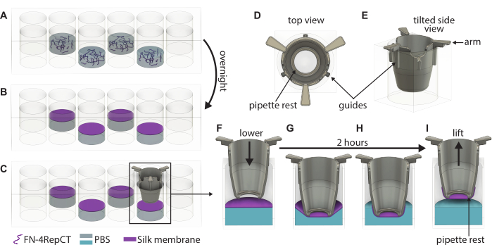
Figure 1: Detailed illustration of formation and lifting of singular FN-silk membranes. (A) Fill every second well (avoid the outer row/column) in a 48-well plate with FN-silk protein solution where (B) it self-assembles into a membrane at the liquid-air interface overnight. (C) Grab the insert with a pair of tweezers and slowly lower it down onto the membrane using the (D,E) guides on the 3D-printed insert to ensure that the insert is lowered perpendicular to the membrane. Magnification of the silk membrane adhesion showing a cross section of the insert (F) right above the membrane and (G) as it touches the silk membrane. Over the 2 h incubation period, (H) the silk membrane spontaneously attaches to the insert, which is then (I) used to lift the membrane from the interface. Abbreviations: FN = fibronectin; PBS = phosphate-buffered saline. Please click here to view a larger version of this figure.
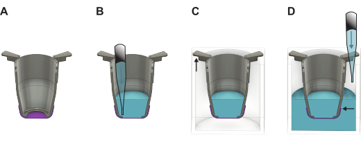
Figure 2: Detailed illustration showing how to handle the FN-silk membrane after lifting it from the formation plate. (A) The insert (gray) with the membrane (purple) directly after lifting. (B) Liquid (blue) is added on the apical side of the membrane, which then is placed in a (C) 24-well plate where the longer part of the insert arms hangs on the walls, and the shorter part keeps the insert positioned in the center of the plate. (D) Liquid is added into the well, ensuring that the liquid level is balanced and above the edge of the membrane. Please click here to view a larger version of this figure.
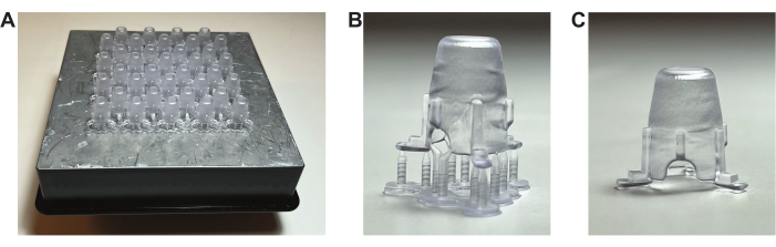
Figure 3: Photographs of the 3D-printed inserts. (A) The inserts directly after being removed from the 3D printer, still attached to the build plate.(B) One insert after being removed from the build plate, prior to breaking the supports. (C) One insert after the supports have been removed. Please click here to view a larger version of this figure.
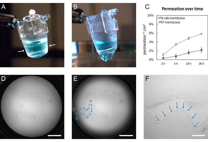
Figure 4: A FN-silk membrane before and after breaking. (A) Photograph of an intact membrane carrying 200 µL of dyed (blue) PBS on the apical side. The membrane edge wrapped around the insert is indicated by white arrows. (B) Photograph of the same membrane after tearing. PBS is leaking through the membrane. (C) Plot showing the permeation of a 3 kDa fluorescent molecule over 36 h through a silk membrane or a commercially available PET-membrane kept under standard cell culture conditions for 9 days. (D) Brightfield image of a membrane before tearing. (E) Brightfield image of the same membrane after tearing. The defective area is indicated by the blue dashed outline. (F) Magnified view of the tear shown in D with the edge of the torn membrane indicated by blue arrows. Scale bars = 1 mm (D,E), 200 µm (F). Abbreviations: FN = fibronectin; PBS = phosphate-buffered saline; PET = poly(ethylene terephthalate). Please click here to view a larger version of this figure.

Figure 5: Keratinocytes (HaCaT) cultured on the FN-silk membrane. On Day 1, keratinocytes have adhered and evenly covered the surface area of the membrane on the apical (A.i) or basal side (B.i) (phalloidin, green). On Day 3, a confluent monolayer is established on the apical (A.ii) or basal (B.ii) side (phalloidin, green). (C) Evaluation of cell viability on the silk membrane (i-iv) compared with a commercial PET membrane (v-viii) in the center (i, ii, v, vi) and periphery (iii, iv, vii, viii) of the cell layer. Live cells are shown in green (i, iii, v, vii) and dead cells in red (i, iii, v, vii) or white (ii, iv, vi, viii). The dashed line marks the membrane-insert interphase. (D) Zoomed in detail, (i) indicating (white arrows) cell adhesion to the membrane (phalloidin, white) and(ii) a tight junction network formed after 3 days in culture (ZO-1, white). Scale bars = 1 mm (top row: A,B), 100 µm (bottom row: A,B,Ci, ii, v, vi), 500 µm (C iii, iv, vii, viii), 50 µm (D). Please click here to view a larger version of this figure.
Table 1: Overview of previous work where membranes have been integrated into cell-culture inserts. Abbreviations: PCL = polycaprolactone; PEGDA = poly (ethylene glycol) diacrylate; PLGA = poly(lactic-co-glycolic acid); PDMS = Polydimethylsiloxane; PC = Polycarbonate; RSS = Recombinant spider silk protein; PLCL = Poly(lactide-co-caprolactone); RHSIF = Recombinant hagfish slime intermediate filament proteins Please click here to download this Table.
Table 2: Overview of previous work summarizing the different cell types cultured on the FN-silk membranes. FN-4repCT (FN-silk) is a short version of the dragline silk of Euprosthenops australis, which is recombinantly produced and functionalized with an RGD motif from fibronectin at a genetic level. This protein is used in all the cases summarized here. Please click here to download this Table.
Table 3: Troubleshooting. Please click here to download this Table.
Supplemental File 1: Design file (.stl) for 3D printing the inserts. Please click here to download this File.
Supplemental File 2: Protocol for printing, post-treatment, and sterilization when using the printer and resin specified in the Table of Materials. Please click here to download this File.
Supplemental Figure S1: Schematic of the pattern suggested to use when placing the FN-silk solution in the 48-well plate. Please click here to download this File.
Discussion
The herein-described protocol outlines a simple way to make biologically relevant cell culture inserts. It begins with printing the inserts, followed by the formation and attachment of FN-silk membranes, and ends with showing how cells can be seeded on both the apical and basal sides of the membrane. There is one truly critical step in this protocol to ensure long-term success with cell cultures and that is the lowering and lifting of the inserts onto the membrane. Successful execution of these steps will yield a silk membrane-insert culture system able to withstand cell culture similarly to commercially available systems with synthetic membranes. To ensure this, guiderails have been implemented on the sides of the custom-designed inserts to prevent them from being lowered at an angle or moved sideways in the well, which would lead to uneven membrane adhesion, generating weak points and subsequently leakage. It is common that minor issues arise when following a protocol for the first time. To aid the new user in circumventing them, should they experience them while following the protocol presented above, we have outlined potential problems and their solutions in Table 3.
The membrane itself has been shown to be beneficial for modeling different barrier tissues (overviewed in Table 2); however, it should be pointed out that the resin used to print the inserts herein has not been extensively tested for its effect on the viability of other cell types. Although we have not encountered any such problems so far, it is possible that the resin could negatively affect the viability and growth of some sensitive cells. It is therefore recommended that a viability test similar to the one presented here is performed to verify the resin's compatibility with each cell type used. If cytotoxicity is experienced, a more thorough curing and/or leaching-out protocol should be established to prevent uncured monomers from leaching out over time and harming the cells. An example of such a protocol, which was used for the resin used to print the inserts within this protocol, can be found in Supplemental File 2. This protocol has previously been used to prepare inserts for culturing of bEnd.3 brain endothelial on silk membranes for up to 8 days15.
The main benefit of the method presented in this work is that it offers a simple way to replace current plastic membranes on tissue culture inserts and, as such, improve static tissue culture models. The main limitation is that the user needs access to 3D-printing equipment or to purchase time at a facility to print their inserts. However, if necessary, this could be circumvented by using commercial tissue culture inserts after removing their membranes. In addition, while the silk membranes, in essence, can be used as regular tissue culture inserts, they are thinner and of protein composition, and therefore, more sensitive than their current synthetic commercial counterparts. Hence, they require more careful handling by the users and need to be kept wet to maintain their elasticity. It should be noted that the membranes can withstand stretching and inflation16,17, making them suitable, for example, for emulating breathing motion. Even so, it is probable that new users will break some membranes in the initial stages, but as their membrane-handling experience increases, the success rate is expected to increase. If problems remain, the user should refer to Table 3 for troubleshooting.
During the last decade, several alternatives to the commercial plastic inserts have been presented (Table 1), and every time the performance of cell cultures has been compared, the new, more biologically relevant membranes have produced better results than their commercial plastic counterparts2,5,6,7,14,22. This has primarily been observed in terms of enhanced barrier function2,5,6,7,14,22, but also in the formation of more native-like cell growth14 and increased interactions through the membrane in co-culture systems7. This trend has previously been observed for the FN-silk membranes when establishing a blood vessel wall model. In this study, HDMEC and smooth muscle cells (SMCs) were grown on opposing sides of the membrane. It was shown that the SMCs secreted a thicker ECM when co-cultured with the HDMEC on the FN-silk membranes as compared to the commercial PET membranes. Similarly, the HDMEC established a tighter barrier on the FN-silk membranes17. The improved cell culture results are likely due to improved cellular communication and more in vivo-like culturing conditions. The FN-silk membrane comes much closer to the native BM in terms of thickness, structure, and mechanical properties. The native BM is between 20 nm and 3 µm22 thin, the PET membranes 10 µm, and the FN-silk membranes around 1 µm, thus falling well within the native range. The structure of the FN-silk membrane is also nanofibrillar16, just like the native BM22, while the PET membrane consists of plastic with track-etched pores, usually between 0.4 µm and 8 µm in diameter7. The PET membranes are also much more rigid than the BM, having a Young's modulus around 2 GPa, compared to the BM which ranges from kPa to MPa, but generally is cited around 250-500 kPa22. The FN-silk membranes have a Young's modulus of 115 kPa16, which falls within the native conditions. It should also be noted that once cells are grown on the membrane, their strength becomes the dominant factor, not the membrane itself17. In the end, it should also be noted that the integrated functionalization of the FN-silk protein ensures that cells adhere directly to the membrane and as such, a coating will not be necessary. For the PET membranes it is often standard to coat with an ECM protein to ensure proper cell adhesion7.
When comparing the FN-silk membrane with other approaches used to replace the PET membrane (overviewed in Table 1), the main advantage of our method is the use of the recombinantly produced functionalized silk protein. This ensures reproducibility and defined culture conditions in contrast with other protein-based, animal-derived materials such as collagen. Note again that the functionalization of the protein ensures that no coatings are needed as cells adhere well to the membranes as it is17. Moreover, the production of silk-based membranes described herein is based on self-assembly and does not require any complex setup or the use of harsh chemicals, unlike many other techniques that rely on, for example, electrospinning. The spontaneous adhesion of the membrane to the insert also eliminates the need for manual handling associated with two-part inserts, gluing, and silicon mounting rings, thereby simplifying scaling and enabling easy reproducibility in any lab. In addition to facile production, our method is easy to adapt to the experimental needs of the user since different insert materials can be used and membrane thickness can be tuned by adjusting the silk concentration of the initial solution16. Lastly, this protocol can yield, to our knowledge, the to-date, thinnest free-standing membrane attached to a tissue culture insert, allowing for the closest resemblance to the native basement membrane.
The silk membrane formation and handling protocol presented here is straightforward to use for anyone accustomed to working with tissue culture inserts in a cell culture lab. It is a simple way to transition away from plastic membranes to a more in vivo-like counterpart, which allows for the generation of more relevant tissue models using various types of cells (Table 2). The silk membranes can support cell culture on their apical or basal sides as well as co-cultures of different cell types bilaterally17. The barrier tissue models developed on the silk membranes can be used for the same range of applications as the tissue culture inserts, including drug screenings and permeation and infection studies. For cases where the crosstalk between different cell types is of interest, they have been shown to outperform the TC-inserts due to their more in vivo-like properties17.
Disclosures
L.G. works for and M.H. has shares in Spiber Technologies AB, the company that produces the FN-silk protein.
Acknowledgements
The authors would like to thank Spiber Technologies AB for providing the recombinant functionalized spider silk protein and Eline Freeze for printing a large portion of the 3D printed inserts.
Materials
| Name | Company | Catalog Number | Comments |
|---|---|---|---|
| CHEMICALS | |||
| Alexa Fluor 488 | Invitrogen; Thermo Fisher Scientific | A-21121 | Goat anti-mouse, Dilution 1:500 |
| Alexa Fluor 488 Phalloidin | Invitrogen; Thermo Fisher Scientific | A12379 | Dilution 1:400 |
| anti-ZO-1 (1A12) antibody | Invitrogen; Thermo Fisher Scientific | 33-9100 | Mouse anti-human, Monoclonal, Dilution 1:200 |
| Dextran, Alexa Fluor 680; 3,000 MW, Anionic | Invitrogen; Thermo Fisher Scientific | D34681 | Diluted 2,5% (w/v) in 200 ul of culture medium |
| DMEM/F-12 | Gibco; Thermo Fisher Scientific | 31330095 | Supplemented with 5% v/v FBS and 1% v/v Penicillin-Streptomycin |
| Ethanol | Solveco | 1326 | 70% (CAS-no 64-17-5) |
| Fetal Bovine Serum, qualified, heat inactivated, United States | Gibco; Thermo Fisher Scientific | 16140071 | |
| FN-silk | Spiber technologies AB | Store at -80 °C | |
| Isopropanol, EMPARTA ACS analytical reagent | Supelco | 1096342511 | ≥99.5% (CAS-no 67-63-0) |
| Live/Dead Viability/Cytotoxicity Kit | Invitrogen; Thermo Fisher Scientific | L3224 | |
| PBS | Swedish Veterinary Agency / Statens veterinärmedicinska anstalt | 992420 | without Ca and Mg, filtered |
| Penicillin-Streptomycin (10,000 U/mL) | Gibco; Thermo Fisher Scientific | 11548876 | |
| MATERIAL | |||
| Dental LT Clear Resin | Denthouse | #DLCL-01 | |
| HaCaT cells | CLS | 300493 | |
| Nunc Cell-Culture Treated Multidishes 24-well | Fisher Scientific | 10604903 | |
| Nunc Cell-Culture Treated Multidishes 48-wel | Fisher Scientific | 10644901 | |
| TC insert, for 24-well plates, PET, transparent | Sarstedt | 83.3932.041 | pore size: 0.4 µm |
| ThinCert Cell Culture Inserts, translusent membrane (PET) | Greiner | 662640 | pore size: 0.4 µm |
| EQUIPMENT | |||
| EVOM meter with chopsticks | World Precision Instruments (WPI) Germany, GMBH | ||
| Form 3B | FormLabs | ||
| Form Wash | FormLabs | ||
| Form Cure | FormLabs | ||
| Isotemp General Purpose Deluxe Water Baths | Fisherbrand | ||
| Inverted fluorescence microscope Eclipse Ti | Nikon | ||
| Inverted fluorescence microscope DMI6000 B | Leica | ||
| Laminar flow hood Ninosafe, class II | Labolutions | ||
| Midi CO2 Incubator, 40 L | Thermo Scientific |
References
- Kumar, P., Kedaria, D., Mahapatra, C., Mohandas, M., Chatterjee, K. A designer cell culture insert with a nanofibrous membrane toward engineering an epithelial tissue model validated by cellular nanomechanics. Nanoscale Adv. 3 (16), 4714-4725 (2021).
- Wang, Y., et al. Ultrathin and handleable nanofibrous net as a novel biomimetic basement membrane material for endothelial barrier formation. Colloids Surf B Biointerfaces. 219, 112775(2022).
- Jain, P., Rauer, S. B., Möller, M., Singh, S. Mimicking the natural basement membrane for advanced tissue engineering. Biomacromolecules. 23 (8), 3081-3103 (2022).
- Eom, S., Park, S. M., Han, S. J., Kim, J. W., Kim, D. S. One-step fabrication of a tunable nanofibrous well insert via electrolyte-assisted electrospinning. RSC Advances. 7 (61), 38300-38306 (2017).
- Kim, D., Eom, S., Park, S. M., Hong, H., Kim, D. S. A collagen gel-coated, aligned nanofiber membrane for enhanced endothelial barrier function. Sci Rep. 9 (1), 1-11 (2019).
- Ebrahim, N. A., et al. Porous honeycomb film membranes enhance endothelial barrier integrity in human vascular wall bilayer model compared to standard track-etched membranes. J Biomed Mater Res A. 111 (5), 701-713 (2023).
- Zakharova, M., et al. Transwell-integrated 2 µm thick transparent polydimethylsiloxane membranes with controlled pore sizes and distribution to model the blood-brain barrier. Advanced Materials Technologies. 6 (12), 2100138(2021).
- Park, S., et al. Use of elastic, porous, and ultrathin co-culture membranes to control the endothelial barrier function via cell alignment. Advanced Functional Materials. 31 (9), 2008172(2021).
- Youn, J., et al. Facile and adhesive-free method for bonding nanofiber membrane onto thermoplastic polystyrene substrate to fabricate 3D cell culture platforms. Materials Today Bio. 20, 100648(2023).
- Liu, H., et al. Electrohydrodynamic jet-printed ultrathin polycaprolactone scaffolds mimicking Bruch’s membrane for retinal pigment epithelial tissue engineering. Int J Bioprint. 8 (3), 550(2022).
- Dogan, A. A., Dufva, M. Customized 3D-printed stackable cell culture inserts tailored with bioactive membranes. Sci Rep. 12 (1), 1-12 (2022).
- Rohde, F., Danz, K., Jung, N., Wagner, S., Windbergs, M. Electrospun scaffolds as cell culture substrates for the cultivation of an in vitro blood–brain barrier model using human induced pluripotent stem cells. Pharmaceutics. 14 (6), 1308(2022).
- Slater, S. C., et al. An in vitro model of the glomerular capillary wall using electrospun collagen nanofibres in a bioartificial composite basement membrane. PLoS ONE. 6 (6), e20802(2011).
- Harris, T. I., et al. Utilizing recombinant spider silk proteins to develop a synthetic Bruch’s membrane for modeling the retinal pigment epithelium. ACS Biomater Sci Eng. 5 (8), 4023-4036 (2019).
- Hjelm, L. C., Hedhammar, M., Löfblom, J. In blood–brain barrier model based on recombinant spider silk protein nanomembranes for evaluation of transcytosis capability of biomolecules. Biochem Biophys Res Commun. 669, 77-84 (2023).
- Gustafsson, L., et al. Recombinant spider silk forms tough and elastic nanomembranes that are protein-permeable and support cell attachment and growth. Advanced Functional Materials. 30 (40), 2002982(2020).
- Tasiopoulos, C. P., Gustafsson, L., Van Der Wijngaart, W., Hedhammar, M. Fibrillar nanomembranes of recombinant spider silk protein support cell co-culture in an in vitro blood vessel wall model. ACS Biomater Sci Eng. 7 (7), 3332-3339 (2021).
- Marino, A., Baronio, M., Buratti, U., Mele, E., Ciofani, G. Porous optically transparent cellulose acetate scaffolds for biomimetic blood-brain barrier in vitro models. Front Bioeng Biotechnol. 9, 630063(2021).
- Schramm, R. A., Koslow, M. H., Nelson, D. A., Larsen, M., Castracane, J. A novel impedance biosensor for measurement of trans-epithelial resistance in cells cultured on nanofiber scaffolds. Biosensors. 7 (3), 35(2017).
- Qi, D., et al. Establishment of a human iPSC- and nanofiber-based microphysiological blood-brain barrier system. ACS Appl Mater Interfaces. 10 (26), 21825-21835 (2018).
- Rickabaugh, E., Weatherston, D., Harris, T. I., Jones, J. A., Vargis, E. Engineering a biomimetic in vitro model of Bruch’s membrane using hagfish slime intermediate filament proteins. ACS Biomater Sci Eng. 9 (8), 5051-5061 (2023).
- Choi, J. W., Youn, J., Kim, D. S., Park, T. E. Human iPS-derived blood-brain barrier model exhibiting enhanced barrier properties empowered by engineered basement membrane. Biomaterials. 293, 121983(2023).
- Widhe, M., Shalaly, N. D., Hedhammar, M. A fibronectin mimetic motif improves integrin mediated cell biding to recombinant spider silk matrices. Biomaterials. 74, 256-266 (2016).
- Johansson, U., et al. Assembly of functionalized silk together with cells to obtain proliferative 3D cultures integrated in a network of ECM-like microfibers. Sci Rep. 9 (1), 1-13 (2019).
- Widhe, M., Johansson, U., Hillerdahl, C. O., Hedhammar, M. Recombinant spider silk with cell binding motifs for specific adherence of cells. Biomaterials. 34 (33), 8223-8224 (2013).
Reprints and Permissions
