Here, we present an optimized methodology for producing mycelium-based composites (MBCs) from petrochemicals and polluting materials for thermal insulation applications. To become carbon-neutral and sustainable, biobased and compostable materials like mycelium bio-composite could be the solution. To determine if they meet the construction standards, several experiments were conducted.
A subscription to JoVE is required to view this content. Sign in or start your free trial.
Method Article
Production and Testing of Moisture Behavior and Thermal Properties of Rapeseed Straw and Ganoderma resinaceum Mycelium Bio-Composites
* These authors contributed equally
In This Article
Summary
Abstract
This research aimed to address the growing demand for sustainable construction materials by developing mycelium bio-composites as innovative, biobased insulation. Utilizing local agricultural lignocellulosic residual by-products bound by mycelium, they offer a promising circular alternative to fossil-based materials. This manuscript is a condensed view of the Mythic project, focused on optimizing growth techniques and material properties to ensure technical feasibility.
In the growth optimization phase, a novel inoculation method using reclaimed cellulose, instead of grain kernel-based inoculants, significantly improved growth speed and substrate colonization, reducing incubation times and aligning with industrial production needs.
Material property optimization focused on thermal properties, fire resistance, and moisture behavior -- key attributes for insulation materials. Mycelium bio-composites achieved thermal conductivity values of 0.034-0.039 W/m·K, comparable to conventional insulators. The moisture behaviour properties are considered to be sufficient for its use as insulation. Hydrophobic properties were enhanced through a coating, improving durability in humid conditions. These innovations ensure that mycelium bio-composites meet industry benchmarks for various applications.
Introduction
In 2022, the construction industry was responsible for 21% of global greenhouse gas emissions and generated 38.4% of the total waste in the European Union1,2. A significant portion of this impact comes from the production and disposal of conventional insulation materials such as expanded polystyrene (EPS) and polyisocyanurate (PIR) foams. These materials are petrochemical-based, energy-intensive to produce, and present long-term environmental risks due to poor biodegradability and high embodied carbon3,4.
To address these challenges, the current study presents an optimized methodology for producing mycelium-based composites (MBCs) for thermal insulation applications. The primary goal of this method is to establish a reproducible, lab-scale approach that can be scaled to industrial contexts, using Ganoderma resinaceum (GR) grown on rapeseed straw (RS). This technique is designed to generate a fully biobased, carbon-negative insulation material with competitive thermal and moisture-regulating properties.
MBCs offer compelling advantages over conventional insulation. They are produced from agricultural waste, require minimal energy input, act as a carbon sink during their lifespan, and decompose naturally at the end-of-life stage, making them a strong candidate for circular building systems5,6. Compared to other biobased alternatives like cellulose or hempcrete, MBCs uniquely combine low thermal conductivity with structural cohesion and hydrophobic tuning, which can be achieved via growth control and post-processing techniques7,8.
The broader literature increasingly supports the relevance of MBCs. Reviews and empirical studies highlight their suitability for thermal and acoustic insulation, their adaptability to different substrate-fungus pairings, and their potential for modular or in-situ production at architectural scales6,9,10. For example, GR-RS MBCs tested under controlled conditions demonstrated a thermal conductivity of approximately 0.045 W/m·K, a specific heat capacity of 1800 J/kg·K, and a compressive strength of up to 0.5 MPa, indicating performance levels suitable for non-load-bearing insulation panels in walls and roofs6,7,8. Furthermore, biomimetic approaches have emerged, framing MBCs as responsive design materials in architectural research11. However, ensuring mechanical consistency and durability across scales remains an active research area12.
MNEXT launched the Mythic project -- Mycelium materials (Mytherials) for thermal insulation in construction. This initiative expands on prior findings that GR and RS form a promising combination for MBC development, focusing on refining growth conditions, material testing according to ISO standards relevant to the insulation application, and evaluating economic and user acceptance parameters for future upscaling.
This technique is particularly relevant for researchers, architects, and manufacturers exploring low-impact building materials with a circular life cycle. The method focuses on insulation applications in walls, roofs, and floors, where low density, thermal regulation, and moisture behaviour are crucial. Key contextual factors include local availability of substrates and fungal species, the scalability of the inoculation and growth process, and compliance with building performance standards. The methodology includes evaluation of thermal conductivity, specific heat capacity, moisture response, and water repellence, enabling users to assess its applicability based on environmental conditions and regulatory requirements.
This manuscript presents the outcomes of that work: a lab-scale yet scalable method for producing GR-RS MBCs, including optimized growth parameters and material testing protocols. While GR-RS is the focus, the protocol is adaptable to other fungal species and substrates, making it relevant for varied geographies and feedstock availability. Although the method is effective at a laboratory or pilot scale, further adaptations may be necessary for large-scale implementation to ensure consistency and cost-efficiency.
Access restricted. Please log in or start a trial to view this content.
Protocol
The materials, equipment, machines, and associated software used in this article are listed in the Table of Materials. The protocol is divided into two major sections, MBC production and material testing.
1. MBC production
- Spawn preparation
- Dissolve 20 g of Malt Extract Broth powder in 1 L of demineralized water (or 2 g per 100 mL broth) in a 1 L Erlenmeyer flask. Mix the contents in the Erlenmeyer flask using a heated stirring device at 150 °C.
- Cover the flask with a permeable cap, such as a cotton-ball-gauze in an aluminium foil stopper, and autoclave the mixture at 121 °C for 25 min. The malt extract broth (MEB) is ready for use.
NOTE: For every step with an autoclave, check the water level inside the autoclave and the exhaust, ensuring the water level is between the minimum and maximum levels. Any water added to the autoclave (or any water going into the autoclave) should be demineralized to ensure optimal operation, as the minerals may cause problems with machine operation. All autoclavable items are marked with autoclave indicator tape, which develops black stripes after sterilization, confirming that the autoclaving process was successful. Always let the contents cool down to room temperature (RT) before starting the next step. - Add cellulose into an autoclavable bag 1:1.32 per gram of cellulose of demineralized water.
- Massage the bags manually for 2 min to ensure even distribution of water within the cellulose.
- Label bags (inoculum media - fungal type - date - weight - initials researcher) and stick autoclave tape on the bag.
- Autoclave the bags at 121 °C for 25 min, containing cellulose mixed with water.
- Once the autoclave cycle is finished, place cellulose bag(s) in the laminar airflow hood (LAF) until cooled down.
NOTE: When operating in the LAF, maintaining strict sterility is crucial. Procedures carried out in this environment are highly sensitive, and improper handling can significantly increase contamination rates. It is recommended to clean the LAF cabinet and all items to be placed inside it by wiping them first with a medicarine solution (1 tablet per 10 L of water), followed by wiping them with 70% ethanol, both before and after the procedure. - Use a sterile inoculation loop or a sterile spatula to cut a fully colonized 100 mm diameter Petri dish of GR into four equal sections.
NOTE: The GR plate is bought as mother spawn. The mother spawn can be replicated in the lab by a biological lab technician; however, the process is out of scope in this manuscript. - Sterilize the lab blender cup by autoclaving it at 121 °C for 25 min, before placing it in the LAF, wipe the outside with medicarine solution and 70% ethanol.
- Transfer two sections to the sterile lab blender cup and add 50 mL of MEB (prepared in 1.1.2).
- Place the cup on the rotator and run at low speed for 30 s, ensuring that the entire Petri dish has been adequately trimmed by visually inspecting the mixture.
- Pour the inoculated broth mixture into the bag with the autoclaved cellulose + water mix and massage the contents manually for 2 min.
- Transfer the bag to the climate chamber for 5 days at 30 °C and 80% relative humidity (RH).
- Shake and massage the bag gently for 2 min after 3 days. Place back into the incubator. The spawn is ready after 5 ± 1 days of growth.
- Preparing substrate
- Place an empty bowl or bucket on the scale and tare it. Then transfer the substrate into the bucket and record the weight of the substrate.
NOTE: It is recommended not to use more than 160 g per bag (530 mm x 370 mm) to ensure adequate sterilization of the contents of the bag. Using larger quantities might demand longer sterilization time due to slow heat penetration in large volumes (or larger volume-to-surface ratio). - Weigh water to be added accordingly to the ratio 1.65:1 RS substrate: demineralized water and mix thoroughly using hands, or for larger quantities, a cement mixer.
- Place the mixture into autoclavable bag(s).
- Close bag(s) with a bag sealer or tape.
- Label the bag(s) (substrate type - date - weight - initials) and stick autoclave tape.
- Place bag(s) in the autoclave and start cycle of 121 °C for 25 min.
- Place an empty bowl or bucket on the scale and tare it. Then transfer the substrate into the bucket and record the weight of the substrate.
- Substrate inoculation
- Remove the bags from the autoclave and place them in the LAF cabinet.
- Blend the inoculated cellulose with a kitchen stick-blender at the lowest intensity (cleaned with medicarine solution and ethanol) for 30 s to ensure even homogenous particle dimensions.
- Weigh spawn: 10% of the total weight of the substrate + water (wet-weight) with a scale and pour it inside the bag.
NOTE: The 10% spawn can vary depending on the sterility conditions. At lab conditions, 10% was determined as the best compromise between spawn quantity and contamination. At upscaled conditions, the larger the spawn quantity, the lower the sterility/cleanliness levels necessary for adequate growth. - Seal the bag with a sealer or tape and shake/massage it gently for 2 min to ensure even distribution.
- Label the bags again (substrate type - fungal type - date - weight of substrate - spawn weight - initials).
- Moulding
NOTE: This step can be performed either immediately after substrate inoculation or within five days. In this protocol, it is carried out immediately to accelerate the overall process. While timing does not affect the final outcome, after 5 days the material becomes difficult to mould, as it tends to bind tightly together.- Clean the mould to shape the MBC with medicarine solution first and then 70% ethanol before placing it under the LAF cabinet.
NOTE: The moulds used in this study are square 200 mm x 200 mm x 50 mm, in accordance with the dimensions specified in the ISO standards for the planned tests. - Tare the mould on the scale and fill it with the inoculated substrate. Ensure to evenly spread the material across the mould, leaving it completely flat.
- Record the weight to ensure equal density of production for the rest of the moulds, if applicable.
- Cut perforated foil to cover the top surface of the moulds and wipe it with medicarine solution and 70% ethanol.
- Cover the mould with perforated foil and tape it to secure it.
- Label the mould (substrate type - fungal type - date - weight - initials).
- Place the filled moulds in the climate chamber at 25 °C and 80% RH for 7 ± 1 days.
- After 3 days of growth, take the samples out of the mould in the LAF, gently flip them by 180° (upside-down), and cover the moulds with the perforated foil again.
- Clean the mould to shape the MBC with medicarine solution first and then 70% ethanol before placing it under the LAF cabinet.
- Deactivation and drying
- Visually inspect the growth of the samples by observing uniform mycelium colonization and the degree of whiteness.
- After sufficient growth, commonly 7 ± 1 days, demould the sample and deactive growth and dry by placing it in the oven at 65 °C for 24 h and place baking paper underneath to absorb the moisture and keep it from sticking to the oven surface.
NOTE: If drying a larger panel, place a weight on top to prevent warping (with baking paper in between). Consider that for thick panels, it will require more than 24 h of drying. To verify if the sample is completely dry, monitor its weight during oven drying. The sample can be considered dry when the weight change is less than 0.1% over a 24-h period. - Place the bag label(s) near the samples in the oven, or stick the tape on the sample.
- Weigh the sample at the end of the drying process and label it (substrate type - fungal type - date - weight - initials).
- Post-production
- Add a hydrophobic coating by evenly applying 10 mL using a low-pressure spray and leave to dry for 24 h in a ventilated space.
- Submerge the sample in 50 mL of the coating to apply a second layer and leave to dry for another 24 h in a ventilated space.
- Weigh the sample using a scale and add the coating type and final weight to the label.
2. Material testing
NOTE: Supplementary files, including step-by-step screenshots, are provided for the software usage in both the thermal properties (Supplementary File 1) and compressive strength measurements (Supplementary File 2). The samples for the testing are all conditioned at a steady room temperature (23 ± 5) °C and 50 ± 20% relative humidity for 48 h before testing.
- Measuring thermal conductivity
NOTE: In this research, thermal conductivity and specific heat capacity were measured using a heat-flow meter (HFM) based on standard NEN-EN ISO 8301, which is specifically intended for determining the thermal properties of insulation materials13.- Start the HFM software and left-click on the Autocalibration tab.
- Left-click on the HFT calibration button.
- Enter the basic data and configure the set points in the table. Set the upper plate temperature to 17.5 °C and the lower plate temperature to 2.5 °C, resulting in a mean temperature of 10 °C.
- Left-click on Reference description. Weigh and measure the Calibration Standard Netzsch EPS 200 mm and input this into the software.
- Place the EPS piece in the HFM, close the door, and left-click to tick the load setpoint at 2.1 kPa, then left-click on the Start button.
NOTE: Once stability is reached, the calibration and testing will stop automatically. - In the HFM software, left-click on the Wizards button and then left-click on Thermal Conductivity Test.
- Input the basic data and specimen description. Set the same values as 2.1.3 in the set point table. Use the built-in thickness gauge to measure the thickness of the sample.
NOTE: When inputting the basic data, ensure to change the sample ID, file name, and destination per sample - Place the MBC sample in the HFM and close the door, ensuring to keep the sample centered.
- Select the calibration previously performed and left-click to tick the load setpoint at 2.1 kPa, then left-click on the Start button.
- Measureing specific heat capacity
- Left-click on the Autocalibration button.
- Left-click on the Empty Stack Correction button.
- Input the basic data, set the three-step temperature shown in Table 1, and drive plate to 0.25 cm thickness. Then press Start.
- Once the empty stack calibration is finished, left-click on the Wizards button and then left-click on Specific Heat Test.
- Place the MBC sample inside the HFM and close the door.
- Input the basic data and specimen description. Use the built-in thickness gauge to measure the thickness of the sample.
- Set the same values as 2.2.3 in the set point table and select the empty stack calibration performed previously. Left-click to tick the load setpoint at 2.1 kPa, then left-click on the Start button.
- Access the data per sample by left-clicking the Reports button.
- Moisture absorption/desorption
NOTE: The standard, ISO 23327:2021, is relevant for insulation materials14.- Prepare a water box quarter-filled with water, as shown in Figure 1. Place three strips of plastic tape to hold the sample in position, ensuring it remains suspended and does not come into contact with the water. The setup resembles Figure 1.
- Precondition the plastic box in a room at a temperature of 23 ± 5 °C and wait for 24 h before starting the experiments.
- After 24 h, place the sample on top of the plastic tape.
- At the intervals of 0 h (before experiment), 0.5 h, 1 h, 2 h, 4 h, 8 h, 24 h, and 48 h take the MBC sample out of the box, weigh it on a scale, and measure its dimensions according to Figure 2. Once weighed, place inside the box again and close the lid.
NOTE: Be as fast as possible in the weighing and measuring step to avoid losing moisture. - After 48 h, take the sample out of the box and place the sample in a climate chamber at 25 °C and 40% RH.
- At the same intervals as 2.3.5, weigh the sample to determine weight loss.
- After 48 h the experiment is finished and curves are produced: absorption/desorption in weight (kg), against time (h), and dimensional stability (%) against time (h).
- Calculate the mass change (%) by:
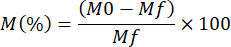
M0 is the initial mass of the sample
Mf is the final mass after the absorption test - Calculate the average of each dimension: length (), base (), and thickness () at each interval.
For each dimension:
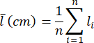
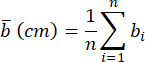
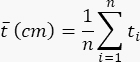
n is the number of measurements
li, bi, ti = individual measured values - Calculate the dimensional change (%) at each interval using the formula.

 is l, b, or t.
 - Calculate the initial volume (cm3) and at each interval.


- Calculate the volumetric dimensional change (V%) at each interval.

- Compressive strength (moisture behaviour)
NOTE: The 10% strain compressive strength testing following standard ISO 29469 was used as it is meant for insulation materials15. The universal testing machine (UTM) setup with squared compression plates (250 mm x 250 mm) was used. This machine enables a wide range of mechanical tests, including compression, tension, and shear testing. The compressive strength is measured when dry, humid, and post-dried to understand the moisture behaviour of MBCs.- Measure the dimensions of the MBC sample using a vernier caliper, according to Figure 2.
- Place the sample in the UTM, centered above the lower compression plate.
- Turn on the UTM first, then start the software. Follow this order; otherwise, the machine will not connect properly and will remain in demonstration mode.
- In the UTM software, left-click on the Library Tools tab and left-click on the Library Methods sub-tab.
- Search for Iso 29469 in the Search tool, then right-click on the standard and press Edit Method.
NOTE: Not all UTM software libraries have this standard. The configuration of this test requires setting the UTM segments to a speed of 5 mm/min, and setting the limit of the experimentation to 10% strain (10% of the initial thickness of the sample). - Press Start Experiment on the UTM software.
- Calculate 10% compressive strength in Pascals (Pa) (σ10) using the formula:
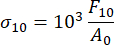
F10 is the force at 10% strain, in Newtons (N)
A0 is the initial cross-sectional area of the specimen, in square metres (m2). - Calculate the compressive modulus in Pa.

Δσ is the change in compressive strength, in Pa.
Δε is the change in strain, in %. - Condition new samples in the water box from Figure 1 for 24 h and repeat steps 2.4.1 to 2.4.8 for the humid samples.
NOTE: Condition extra samples in the water box from 2.4.9 to then dry them for use in 2.4.10. - Transfer non-tested, humid samples into an oven at 50 °C for 12h and with fan ventilation, then repeat steps 2.4.1 to 2.4.8 for the post-dried samples.
- Water repellence
- Prepare a solution by mixing 9 mL of water with 1 mL of red water colorant using a 10 mL measuring cylinder. Mix well with a spoon.
- Divide the surface of the sample into four quadrants as shown in Figure 3, using a thin piece of tape or a thin felt-tip pen.
- Measure 100 µL of the red-dyed water using a micropipette and place one droplet in each quadrant of the sample. Make sure the droplet is placed on a flat surface area in each quadrant.
NOTE: Ensure the droplet is released in a single motion; otherwise, it can disturb the surface tension and give an invalid result. If the droplet disperses at this volume, use 50 µL instead and note the change. - With a tripod-held camera at eye level with the top surface of the sample, take a picture of each droplet.
- Using open-source image processing software, measure the contact angle on both sides of each droplet. Calculate the average contact angle using the formula:

- After measuring all four quadrants, calculate the overall average contact angle for the sample using:

Table 1: Step temperatures for specific heat capacity. This table lists the defined temperature intervals (in °C) used to evaluate the specific heat capacity of the MBC samples. Each step represents a range used during controlled heating and must be used as input for the HFM. Please click here to download this Table.
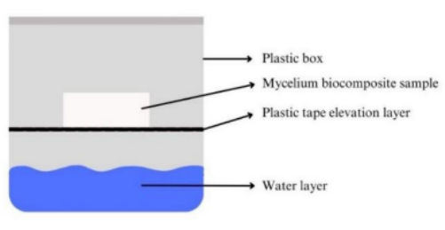
Figure 1: Moisture absorption-desorption setup. This diagram shows the experimental setup used to test the moisture absorption and desorption behavior of the MBCs. Samples were placed under controlled temperature and humidity conditions. No scale bar is needed as the setup overview is qualitative. Please click here to view a larger version of this figure.
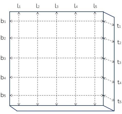
Figure 2: Measuring dimensions of MBCs. The diagram shows where to measure dimensional changes in MBCs before and after humidity cycling. Measurements were taken at multiple equidistant points per sample (n = 5) for length, base, and thickness with a vernier caliper (accuracy ± 0.1 mm). Please click here to view a larger version of this figure.

Figure 3: Surface division for water repellence testing. This diagram illustrates how each sample was subdivided into equidistant quadrants for systematic water droplet testing. Please click here to view a larger version of this figure.
Access restricted. Please log in or start a trial to view this content.
Results
MBC production
The MBC should be mostly white on the surface. The sample should resemble the structure, colour, and homogeneity of the samples in Figure 4 and Figure 5.
Access restricted. Please log in or start a trial to view this content.
Discussion
A key step in the development of MBCs is the preparation of spawn, which must be performed under strict sterile conditions by a trained laboratory technician. This process is sensitive to contamination and requires a high level of skill in aseptic techniques. Proper training in biological safety and laboratory handling is essential, as the quality of the spawn directly affects the colonization efficiency and homogeneity of the final material. The entire spawn preparation should be completed in a single session to maintai...
Access restricted. Please log in or start a trial to view this content.
Disclosures
The authors declare no conflicts of interest and have no relevant disclosures.
Acknowledgements
Mythic was a publicly funded research project supported by SIA Regio-orgaan and conducted as a consortium. All project outcomes are fully aligned with the FAIR principles (Findable, Accessible, Interoperable, and Reusable). Sincere gratitude to the following partners for their invaluable contributions, expertise, and collaboration throughout the project. In alphabetical order:
Agrodome B.V., Fred van den Burgh;
Avans University of Applied Sciences - Caradt, Simone van de Broek
FRAAi Architechten, Lydia Fraaije
HZ University of Applied Sciences, Lennart Zoeter
Impershield Europe B.V., Willem Kemmers
Mogu S.R.L ., Annalisa Moro
Nýlausn, Hörður Sveinsson
Recell B.V., Yme Flapper
Troldtekt B.V., Janine van Cann
Utrecht University, Dr. J.F. (Jordi) Pelkmans and Prof. dr. H.A.B. (Han) Wösten
Verbruggen-paddestoelen B.V., John Verbruggen
Their commitment and collaboration have been instrumental in the development and success of this research.
Access restricted. Please log in or start a trial to view this content.
Materials
| Name | Company | Catalog Number | Comments |
|---|---|---|---|
| 1 L Erlenmeyer flask | Glazen-en-potten.nl | GT00148 | |
| 1 L Measuring cylinder | Sigma-Aldrich | 213905408 | |
| 50 mL Measuring cylinder | Sigma-Aldrich | Z740856 | Aldrich Essentials graduated cylinder, class A, meets DIN ISO 4788 |
| 70% ethanol | Boomlab | 8,00,12,02,72,500 | |
| Autoclavable bag | SacO2 | PPD75/REH6/V37*53 | |
| Autoclave | VWR | TUTT210001 | |
| Autoclave tape | Sigma-Aldrich | BR61750 | |
| Bag sealer | Profipack | 101481 | Model HC-300 |
| Calibration standard Netzsch EPS 200 mm | Netzsch | HFM446S0A95.001-00 | |
| Cellulose | Recell | https://recell.eu/markets/#recell-compose | Delivered by a project partner |
| Ganoderma resinaceum | Westerdijk Instituut | CBS 194.76 | |
| Heat flow meter (HFM) | Netzsch | https://analyzing-testing.netzsch.com/en/products/thermal-conductivity/hfm-446-lambda-eco-line-1 | HFM 446 Lambda Small Eco-line |
| Heated stirring device | Labinco | 32000 | |
| Horizon software | Horizon Software | https://www.tiniusolsen.com/product/horizon-software/ | Software for operating UTM |
| Hydrophobic coating | Impershield Europe | https://impershield.eu/product/bioseal-mycelium/ | Impershield BioSeal Mycelium |
| ImageJ | ImageJ | https://imagej.net/ij/ | Software for processing images |
| Inoculation loops | VWR | DIFC220217 | |
| Kitchen stick-blender | Bosch | MSM6M810 | |
| Lab blender | Labowebshop | AXMX1000XTEES | 2L Waring lab blender |
| Laminar airflow hood (LAF) | MSE Supplies | LS1309 | MSE PRO 43” Width Horizontal Laminar Flow Cabinet |
| Level | Manutan | A830619 | waterpas - I-beam basic - Stanley |
| Malt extract broth powder | BoomLab | 7,00,00,05,90,500 | |
| Medicarine | Ecolab | 3021760 | |
| Micropipette | Sigma-Aldrich | FA10006M | PIPETMAN P1000L Micropipette Metal eject |
| Perforated foil | Scabro | 414075 | |
| Proteus SmartMode 8.5 | Netzsch | https://analyzing-testing.netzsch.com/en/products/thermal-conductivity/hfm-446-lambda-eco-line-1 | Software for operating HFM |
| Scale | VEVOR | https://www.vevor.nl/analytische-balans-c_11079/vevor-digitale-laboratoriumweegschaal-laboratorium-analytische-weegschalen-5000g-p_010521620455?lang=en&srsltid=AfmBOopchyZ-medHCTmpdHiqjXOtvV7xCOdhXZ VIKi9LowzUk6ibehSx | Model HZ-B50002 |
| Substrate | Greenport West-Holland | - | Rapeseed straw delivered by project partner. |
| Universal testing machine (UTM) | Tinius Olsen | https://www.tiniusolsen.com/product/model-50st/ | Model 50ST |
| Vernier caliper | Sigma-Aldrich | Z136115 |
References
- Global Status Report for Buildings and Construction: Beyond foundations - Mainstreaming sustainable solutions to cut emissions from the buildings sector. , United Nations Environment Programme. (2024).
- Waste Statistics. , Eurostat. At https://ec.europa.eu/eurostat/statistics-explained/index.php?title=Waste_statistics#Data_sources (2025).
- Zhao, J. R., Zheng, R., Tang, J., Sun, H. J., Wang, J. A mini-review on building insulation materials from perspective of plastic pollution: Current issues and natural fibres as a possible solution. J Hazard Mater. 438, 129449(2022).
- Torres-Regalado, P., Santiago-Calvo, M., Gimeno, J., Rodríguez-Pérez, M. A. Thermal conductivity aging and mechanical properties of polyisocyanurate (pir) foams produced with different contents of HFO. J Appl Polym Sci. 140 (40), e54504(2023).
- Livne, A., WoSten, H. A., Pearlmutter, D., Gal, E. Fungal mycelium bio-composite acts as a co2-sink building material with low embodied energy. ACS Sustainable Chem Eng. 10 (37), 12099-12106 (2022).
- Elsacker, E., Vandelook, S., Brancart, J., Peeters, E., De Laet, L. Mechanical, physical and chemical characterisation of mycelium-based composites with different types of lignocellulosic substrates. PLoS One. 14 (7), e0213954(2019).
- Appels, F. V., et al. Fabrication factors influencing mechanical, moisture-and water-related properties of mycelium-based composites. Mater Des. 161, 64-71 (2019).
- Girometta, C., et al. Physico-mechanical and thermodynamic properties of mycelium-based biocomposites: A review. Sustainability. 11 (1), 281(2019).
- Attias, N., Danai, O., Ezov, N., Tarazi, E., Grobman, Y. J. Developing novel applications of mycelium based bio-composite materials for design and architecture. Proceedings of Building With Biobased Materials: Best Practice and Performance Specification. , Zagreb, Croatia. (2017).
- Jones, M., et al. Thermal degradation and fire properties of fungal mycelium and mycelium-biomass composite materials. Sci Rep. 8 (1), 17583(2018).
- Elsacker, E., et al. A comprehensive framework for the production of mycelium-based lignocellulosic composites. Sci Tot Environ. 725, 138431(2020).
- Hartley, K., Schülzchen, S., Bakker, C. A., Kirchherr, J. A policy framework for the circular economy: Lessons from the EU. J Clean Prod. 412, 137176(2023).
- Thermal Insulation - Determination of Steady-State Thermal Resistance and Related Properties - Heat Flow Meter Apparatus. ISO 8301:1991. , ISO. at https://www.iso.org/standard/15421.html (1991).
- Hygrothermal Performance of Building Materials and Products - Determination of Moisture Adsorption/Desorption Properties in Response to Periodic Temperature Variation. ISO 23327:2021. , ISO. at https://www.iso.org/standard/75239.html (2021).
- Cellular Plastics - Determination of Compression Properties. ISO 844:2021. , ISO. at https://www.iso.org/standard/73560.html (2021).
- Standard Test Method for Corona-Treated Polymer Films Using Water Contact Angle Measurements. ASTM D5946-17. , ASTM International. at https://www.astm.org/d5946-17.html (2017).
- Houette, T., Maurer, C., Niewiarowski, R., Gruber, P. Growth and mechanical characterization of mycelium-based composites towards future bioremediation and food production in the material manufacturing cycle. Biomimetics. 7 (3), 103(2022).
Access restricted. Please log in or start a trial to view this content.
Reprints and Permissions
