This manuscript presents a novel, innovative 3D-printed illumination device for studying Rose Bengal-mediated photodynamic therapy in vitro.
Method Article
Development of an Innovative LED-based Illumination Device for In Vitro Application of Photodynamic Therapy with Rose Bengal
* These authors contributed equally
In This Article
Summary
Abstract
This article describes a new photodynamic therapy (PDT) device for evaluating the efficacy of Rose Bengal (RB)-mediated PDT in vitro. The device, called CELL-LED-550/3, consists of two 3D-printed parts, one generating a 550 nm green light from a single LED (the light source part) and the other distributing this light to a 96-well cell culture plate (the light distributor part). The light source part is controlled by a driver with three different modes, enabling the light distributor part to deliver three different irradiance levels to the bottom exterior surface of the wells: 0.02 mW/cm2, 0.23 mW/cm2, or 0.62 mW/cm2. The light distributor part was designed to illuminate the wells individually and simultaneously. To demonstrate the relevance of the CELL-LED-550/3 device, its ability to induce cell death by RB-mediated PDT on HepG2 hepatocellular carcinoma cells was evaluated. First, HepG2 cells were treated for 2 h with increasing concentrations of Rose Bengal, a photosensitizer with an absorption peak (the highest one) at around 550 nm. The treated cells were then illuminated using the CELL-LED-550/3 device set to its maximum irradiance level at light doses of 0.3 J/cm2, 0.6 J/cm2, and 1.2 J/cm2 (respectively, with illumination times of 8 min and 4 s, 16 min and 8 s, and 32 min and 16 s). Finally, viability was measured using Cell-Titer Glo at 24 h post-PDT. The experimental results show that RB-mediated PDT using the CELL-LED-550/3 device is capable of inducing a decrease in the viability of HepG2 cells, in a manner dependent both on the concentration of Rose Bengal and on the administered dose of light. Based on the proof of concept presented in this article, the CELL-LED-550/3 device adds a further tool to the study of RB-mediated PDT.
Introduction
With more than 905,000 new cases and 830,000 deaths in 2020, the primary liver cancer is the seventh most common cancer and the second leading cause of cancer-related deaths worldwide1. Among primary liver cancers, hepatocellular carcinoma (HCC) is the most common form, accounting for approximately 90% of cases2. Due to undetected chronic liver disease and poor surveillance compliance, only 25% of the patients with HCC are diagnosed at the early stage of the disease3. These early-diagnosed patients are typically treated by hepatic resection, liver transplantation, or local ablative therapies with curative intent and demonstrate good prognosis with a five-year survival rate over 70%4,5. For the other 75% of patients (those with intermediate- or late-diagnosed HCC), although innovative treatment modalities including targeted therapies, immunotherapies, and combination regimens bring survival benefit6, the prognosis remains very poor: the five-year survival rate in fact does not exceed 30% for this group of patients and drops to 2% for the subgroup of metastatic patients6. Exploring alternative treatment options, therefore, is crucial to improve treatment outcomes and prolong survival in patients with intermediate or advanced-stage HCC. Photodynamic Therapy (PDT), which is an anticancer therapy widely practiced in dermatology7, could be a suitable alternative candidate.
PDT is a photochemical treatment that combines the use of a photosensitizing agent (PS), an appropriate wavelength of visible light, and molecular oxygen to generate cytotoxic reactive oxygen species (ROS)8. The anticancer effects of PDT are derived from three ROS-induced mechanisms9: first, direct cytotoxic effects on malignant cells10, then damage to the tumor vasculature that induces tumor tissue hypoxia, nutrient deprivation and regression11, and finally induction of inflammatory reaction through the release of danger signals and tumor antigens from damaged or dying tumor cells12. For more than three decades, PDT has been the subject of intense investigation aiming to evaluate its potential to treat various types and forms of cancer13,14,15,16,17,18. Based on its efficacy proven from these investigations19,20,21, PDT is nowadays currently used in dermatology for the treatment of non-melanoma skin cancers7. For the other indications, the number of clinical studies has increased in recent years, demonstrating the significant efforts to bring PDT, used alone or in combination with standard treatments, into clinical practice22,23,24.
There exists a variety of photosensitizing agents used for PDT25. Among them, Rose Bengal (RB) has been shown to act as an efficient photodynamic agent against larynx tumor cells26, melanoma cells27, breast cancer cells28, and prostate cancer tissues29. The work presented in this article is based on the need to evaluate whether RB-mediated PDT is also efficient for HCC cells.
Such an evaluation indeed required the prior development of a green LED-based device dedicated to the 550 nm illumination of 96-well cell culture plates. A design in two parts was implemented for this device30: a light source part generates a 550 nm green light from a single LED, while a light distributor part distributes this light, through the use of an optical fiber bundle, to the 96 wells individually and away from the LED. This two-part design first prevents the cells from harmful thermal effects that may arise due to the uncontrolled heat generated within the LED and, second, enables to illuminate the cells inside a cell culture incubator while keeping the light source part with its electronic components (including the LED) outside. These innovative features give the so-called CELL-LED-550/3 device major advantages over the already-published LED-based systems that have been specifically designed for multi-well plate illumination31,32,33,34,35.
In this article, the CELL-LED-550/3 device is first described in detail. Then, as a proof of concept, a cell viability study demonstrates the efficacy of RB-mediated PDT using CELL-LED-550/3 in a 2D HCC cell culture model (HepG2)30. In addition to being inexpensive and portable, the CELL-LED-550/3 device therefore is also a particularly relevant tool for RB-mediated PDT experiments.
Protocol
The details of the reagents and the equipment used in this study are listed in the Table of Materials.
1. Device construction
NOTE: The two parts of the CELL-LED-550/3 device are manufactured separately and, only as the last step, they are plugged together.
- Construction of the light source part
- Attach a properly sized fan heat sink assembly to the back side of the printed circuit board (PCB) on which the 550 nm 3 W LED is mounted.
- Cover the LED with a clear PMMA (polymethyl methacrylate) collimating lens in order to first homogenize the light beam and second to reduce the beam angle from 120° to 10°. Such a reduction allows to increase the amount of light delivered to the light distributor part.
- Connect the LED to the current driver with tri-mode dimming, which enables different irradiance levels to be delivered.
- Build separately the housing, the housing front and the housing closure in 3D printing (red boxes in Figure 1).
- Install the driver and the LED equipped with both the lens and the fan heat sink assembly in their dedicated places in the housing (blue boxes in Figure 1).
- Install the power jack and the rocker switch in their dedicated places in the housing closure (blue boxes in Figure 1).
- Connect the driver and the fan heat sink assembly to the power jack through the rocker switch.
- Assemble the housing, the housing closure, and the housing front.
- Check that the LED is aligned with the axis of the cylindrical opening of the housing front.
NOTE: The cylindrical opening of the housing front is intended for the optical connection of the light source part (female connector) with the light distributor part (male connector).
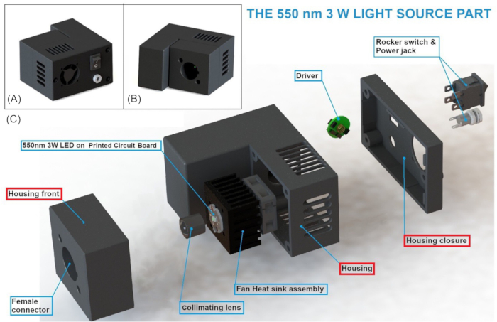
Figure 1: Three-dimensional front (A), back (B), and exploded (C) views of the light source part. Adapted from Lefebvre, A. et al.30. Please click here to view a larger version of this figure.
- Construction of the light distributor part
- Build separately the housing bottom closure, the housing, and the top closure in 3D printing (together they form a hollow box) (red boxes in Figure 2).
- Build the 96-well spacer in white 3D printing (red box in Figure 2) so that it exactly fit onto the hollow box mentioned in 1.2.1. The white color aims to maximize the light reflection and thus to optimize the light distribution.
NOTE: The diameter and center spacing of the circular openings present in the 96-well spacer should be equal to the diameter and the center spacing of the wells of the 96-well plate used for biological assays. - Drill 96 small holes in the top closure of the hollow box so that they are aligned with the center of the 96 circular openings in the 96-well spacer, when the latter is placed onto the top closure.
- Insert a 0.5 mm diameter plastic optical fiber, from bottom to top, in each of the 96 small holes of the top closure.
- Apply polyester resin to the bottom of the top closure to bond the 96 optical fibers to the top closure.
- After the resin dries, polish the distal extremities of the optical fibers until they adjust to the top of the top closure.
- Gather the optical fibers inside the hollow box mentioned in step 1.2.1 into a single bundle protected by a sheath, which extends for around two meters out of the box.
NOTE: The height of the box should be sufficient to prevent bending of the optical fibers and optical attenuation that may be caused. - Assemble the hollow box so that the fiber bundle passes through the dedicated opening of the housing.
- Set the proximal extremities of the optical fibers together into a 3D-printed male connector, allowing the connection to the light source part (female connector).
NOTE: This connector should not require the need for glue to prevent light attenuation that this glue may cause. - Place the 96-well spacer onto the hollow box.
- Create a screen by inserting a tracing paper between a transparent PMMA plate (bottom face) and a scratchproof mylar sheet (top face) in order to diffuse the narrow beam delivered at each optical fiber distal extremity into a beam as large as the well diameter of the 96-well plate used for biological assays.
- Build the screen frame in 3D printing (red box in Figure 2) so that its center opening exactly fits with the size of the 96-well plate used for biological assays and, thereby, the wells perfectly align with the circular openings of the 96-well spacer.
- Fix the screen to the top of the 96-well spacer with the screen frame.
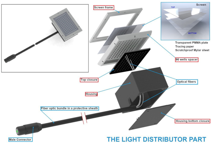
Figure 2: Three-dimensional views of the light distributor part. Adapted from Lefebvre, A. et al.30. Please click here to view a larger version of this figure.
- Assemblage of the light source part with the light distributor part
- Plug the male connector of the light distributor part into the female connector of the light source part.
NOTE: Once the male connector is plugged into the female one, the light beam delivered by the light source part should cover a little more than the surface area of the light-receiving element of the light distributor part, thus ensuring the supply of light to the 96 optical fibers.
- Plug the male connector of the light distributor part into the female connector of the light source part.
2. Biological assays
- Cell culture process
- Cultivate hepatocarcinoma cell line HepG2 in RPMI 1640 medium supplemented with 10% heat-inactivated bovine serum and 1% streptomycin and penicillin.
- Maintain the culture flasks containing HepG2 cells in a 5% CO2 cell culture incubator at 37 °C.
- Change the culture medium every 3 days by aspirating the culture medium from the flasks and replacing it with RPMI 1640 culture medium previously heated to 37 °C.
- Use a microscope to check the confluence of the cells in the culture flasks until they reach 80%-90% confluence.
- Seeding process
- Remove the cells from the incubator and place them under the pre-cleaned microbiological safety station.
- Remove the culture medium from the culture flasks.
- Wash the culture flasks with phosphate buffer solution.
- Apply 3 mL of trypsin (0.25%, 0.53 mM) to the cells and place the culture flasks in the incubator at 37 °C for 5 min to detach the cells.
- After 5 min, recover the trypsin from the culture flasks with 7 mL of culture medium and recover the entire solution of medium + trypsin + cells in a 15 mL tube.
- Count the cells using a cell counter. To do this, take 20 µL of the solution containing the cells and place it in a tube. Add 20 µL of trypan blue solution and place the cell + trypan blue solution on the counting slide and insert into the cell counter.
- Once the cells have been counted, dilute them in culture medium to obtain a 150,000 cell/mL solution and seed the cells in a white 96-well plate with a clear flat bottom at a rate of 1.5x10⁴ cells/ well. The white color aims to maximize the light reflection and distribution inside the wells.
NOTE: The number of cells per well must be adjusted according to the cell line used. A prior density test may be required to find the right number of cells to seed. - Prepare two plates for each viability reading time. One plate will be illuminated and one will remain dark.
- Incubate the plates for 24 h before treatment to allow cell attachment.
- Rose Bengal treatment
- Prepare a stock solution of Rose Bengal by reconstituting Rose Bengal powder in 10% saline solution. This solution must be prepared just before cell treatment to avoid any degradation of the Rose Bengal due to its stability.
- Prepare Rose Bengal solutions at increasing concentrations (0 µM, 5 µM, 10 µM, 25 µM, 50 µM, 75 µM, 100 µM) by diluting the previously prepared Rose Bengal stock solution in the cell culture medium.
- Once the solutions have been prepared, remove the culture medium from the plates containing the cells and add 100 µl of Rose Bengal treatment solutions.
- Incubate the cells with Rose Bengal treatment for 2 h to allow Rose Bengal internalization.
NOTE: The incubation time for the Rose Bengal solution may differ depending on the cell line used. The kinetics of Rose Bengal incorporation may need to be fine-tuned by fluorescence measurement in order to find the right incubation time for each cell line studied. - After 2 h, remove the Rose Bengal solutions, wash the cells twice with PBS, and add 100 µL/well of Rose Bengal-free culture medium.
NOTE: Additional washes with PBS may be necessary for higher concentrations of Rose Bengal. A visual check can be made to ensure that the cells have been washed correctly. Once sufficiently rinsed, the PBS should not take on a pink color due to the Rose Bengal present outside the cells. - Cover the microplates with aluminum foil to protect them from exposure to light. Illuminate half of the plates for the PDT assay (see step 2.4). The unilluminated plates will provide control data for the PDT results (dark condition). They will also provide data on the impact of non-photo-activated Rose Bengal on cell viability. The other microplates will be used for exposure to light in the device (PDT condition).
- Operating procedure for the CELL-LED-550/3 device
- Connect the male connector on the light distributor to the female connector of the light source. Then plug the light source into an electrical outlet.
- Remove two microplates (PDT + Dark condition) from the incubator, remove the aluminum for the PDT condition, and place this plate on the light distributor.
- Set the dimmer of the driver to its maximal level to maximize the power delivered by the LED and to obtain an average irradiance of 0.62 mW/cm2 over the 96 wells.
NOTE: The dimmer of the driver should be set to the most appropriate value for the biological assays (among the three available ones). Whatever the dimmer of the driver is set, the low delivered irradiance does not require the use of safety eyewear. - Illuminate the plate until the desired dose of light on the cells is reached. To obtain the desired light dose, two parameters can be adjusted, Time and Irradiance, referring to the following equation:
Light dose (J / cm2 ) = Irradiance (W / cm2) × Time (s) (equation 1).
Irradiance can be modulated by tuning the driver dimmer to obtain 0.02 mW/cm2, 0.23 mW/cm2, or 0.62 mW/cm2, respectively. From the chosen irradiance, equation 1 can be used to calculate the illumination time required to achieve the target light dose. - Once the desired light dose has been reached, switch the device off. Replace the PDT microplate in aluminum and return it to the incubator with the control plate until the viability test is performed.
- OPTIONAL: Illuminate the other plates if necessary, using the same procedure described above.
- Cell viability assay
- After the PDT assay, leave the illuminated plate in the incubator for 24 h before measuring the impact of PDT on the illuminated cells by measuring their viability. The incubation time can be varied to study the more or less long-term effects of PDT on the cells. For each post-PDT incubation time, a non-illuminated plate (dark condition) should be incubated for the same period.
- After the incubation period, take one illuminated and one non-illuminated plate and add 100 µL of reagent from the cell viability assay kit in each well to measure cell viability based on mitochondrial metabolism and ATP production by cells.
- Incubate the multiplate in the dark for 10 min before cell viability measurement.
- After 10 min incubation, read the luminescence emitted in each well using a multimodal reader. The luminescence emitted is proportional to the production of ATP by the living cells at the time of addition of the cell viability assay solution.
- Consider the luminescence value of the untreated (NT) condition as 100% viability, and normalize the luminescence values of the treated conditions to the NT condition to obtain the percentage of viability induced by each treatment.
- Repeat the same cell viability reading protocol for each post-PDT-treatment reading time (e.g., 24 h, 48 h, and 72 h post-treatment).
Results
As shown in Figure 3, the CELL-LED-550/3 device enables the homogeneous illumination, from underneath, of a 96-well plate with 550 nm green light.
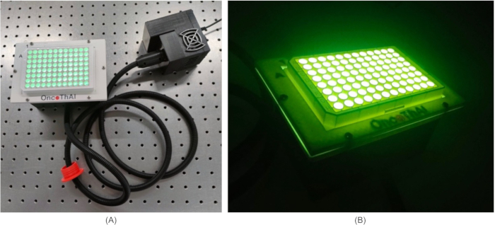
Figure 3: Pictures of the CELL-LED-550/3 device during an illustrative illumination of a 96-well plate when room light is switched ON (A) or OFF (B). Adapted from Lefebvre, A. et al.30. Please click here to view a larger version of this figure.
Each well is illuminated individually and away from the single LED (up to two meters) through the use of a bundle of optical fibers (Figure 4).
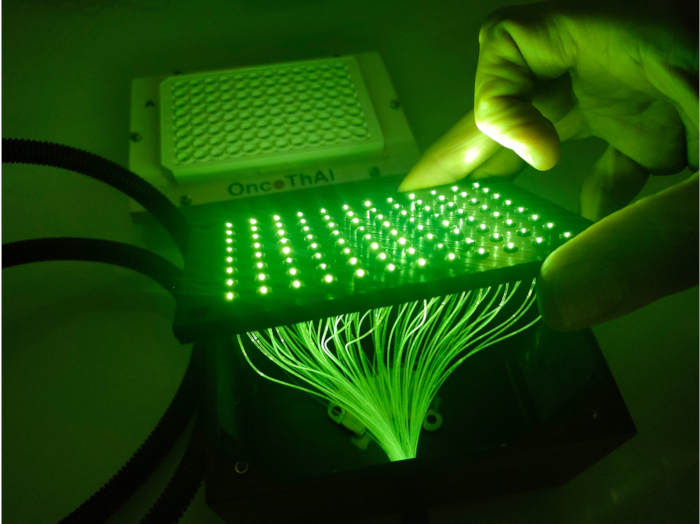
Figure 4: The fiber optical bundle enabling the individual illumination of the wells of a 96-well plate away from the single LED. Please click here to view a larger version of this figure.
To establish the efficacy of the CELL-LED-550/3 device, its ability to induce RB-mediated PDT on the HepG2 hepatocarcinoma cell line was evaluated. Cells were treated with increasing concentrations of Rose Bengal, ranging from 0-100 µM for 2 h before illumination. The use of such a range of concentrations aimed at determining the effective dose (EC50) of Rose Bengal that would kill HepG2 cells when exposed to green light. The impact of the light dose delivered by the CELL-LED-550/3 device on the induction of cell death in HepG2 cells was also studied. To do this, the cells were exposed to light for 8 min 9 s, 16 min 18 s, or 32 min 36 s at an intensity of 0.62 mW/cm2 in order to obtain light doses of 0.30 J/cm2, 0.60 J/cm2, and 1.22 J/cm2, respectively.
First, it was observed that illumination alone, in the absence of Rose Bengal (Light condition, Figure 5), had no effect on the viability of HepG2 cells, regardless of the dose of light received. It was also observed that Bengal Rose alone, in the absence of light (RB condition, Figure 5), did not induce any change in cell viability for any of the conditions tested. In contrast, the results show that RB-mediated PDT using CELL-LED-550/3 is capable of killing HepG2 cells. Furthermore, increased efficacy was observed in correlation with increased light dose, with a maximum effective concentration (EC50) of 34.3 µM for a light dose of 0.30 J/cm2, 26.6 µM for a dose of 0.60 J/cm2, and 6.8 µM for a dose of 1.2 J/cm2.
These results confirmed the effectiveness of this new PDT device for RB-mediated PDT (Figure 5).
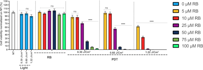
Figure 5: Efficacy of the device in relation to the viability of the HepG2 cell line. Percentage of viability 24 h after treatment of HepG2. NT, non-treated; RB, photosensitizer only (0 µM, 5 µM, 10 µM, 25 µM, 50 µM, 75 µM, and 100 µM); light, illumination for 0.30 J/cm2, 0.60 J/cm2, and 1.22 J/cm2; PDT, illumination with RB treatment. Results are presented as means ± SEM of three independent experiments, expressed as a percentage of the NT. A two-way ANOVA test was performed, with p ≤ 0.01 (**); p ≤ 0.0001 (****) being considered statistically significant, and p ≥ 0.05 considered not significant (NS). Adapted from Lefebvre, A. et al.30. Please click here to view a larger version of this figure.
Discussion
This article describes both the protocol to develop an innovative illumination device dedicated to RB-mediated PDT in vitro and the protocol to implement a proof of concept for the CELL-LED-550/3 device, thus developed30.
CELL-LED-550/3 consists of two parts, each with a specific function. The aim of the first part, referred to as the light source part, is to generate, from a single LED, a homogeneous green light beam with a diameter higher than that of the optical fiber bundle of the second part. This latter, called the light distributor part, aims to distribute, through the optical fiber bundle, the light supplied by the light source part to the wells of a 96-well plate individually and away from the LED. At a distance from the LED up to 2.5 m, the cells can be illuminated as long as needed without any risk of harmful thermal effects that may arise due to the uncontrolled heat generated within the LED.
This feature offers a first significant advantage of CELL-LED-550/3 over the other LED-based systems specifically designed for 96-well plate illumination31,32,33,34,35,36. Indeed, all the other systems involve a positioning of the LED(s) only a few centimeters below the cells (usually below 5 cm), which is insufficient to eliminate the risk of LED-related harmful thermal effects for the cells. To limit such risk, most of these other systems (unfortunately, some do not) include an LED cooling system32,34,35 sometimes positioned very (too) close to the cells, which can then be counter-productively affected by the resulting thermal fluctuations. The design of the CELL-LED-550/3 device in two parts provides another significant advantage over most of the other existing LED-based systems31,32,33,35,36: this allows for illuminating the cells inside a cell culture incubator without any risk for the device. The light distributor part, which includes no electronic components, can indeed be placed inside the incubator, while the light source part, which includes electronic components sensitive to humid environments, is kept outside to prevent the risk of corrosion or failure. Some existing LED-based systems, including electronic components, enable an illumination inside an incubator, but such a use, first, is not recommended by the designers/manufacturers and, second, requires an "adequate" dry after usage33,34. The ability to illuminate the cells inside an incubator and thus to maintain the cells under the same physiological conditions (temperature, humidity, and CO2 concentration) during the protocol is crucial to avoid potential biases in the assessment of cell viability after PDT, especially for protocols requiring long illumination times. It should also be emphasized that the CELL-LED-550/3 device includes a single LED to illuminate all 96 wells individually and simultaneously. This original and innovative feature is not available with any of the other above-mentioned LED-based systems31,32,33,34,35,36. Most of these systems include 96 LEDs, with one LED placed below each well, and therefore deliver 96 individual beams31,33,34,36 while the remaining systems deliver, from 6 to 25 LEDs positioned a few centimeters from the well-plate, a global beam covering all or part of the wells31,32,35. Based on the literature, generating 96 individual beams from a single LED, as CELL-LED-550/3 does through the use of an optical fiber bundle, has never been proposed before.
The light source part includes a 550 nm 3 W LED selected according to two main criteria. First, the emission spectrum of the LED (and therefore its central wavelength) should overlap the absorption spectrum of the RB photosensitizer. Such an overlap, which is perfectly achieved with the selected LED (central wavelength: 554.4 nm; FWHM: 106.4 nm; both estimated following the methodology described in Lefebvre et al.30) (Figure 6), is essential for the RB photo-activation and thereby for the induction of an RB-mediated PDT. Second, the optical power of the LED should be lower than 5 W. This power limitation is imposed by the admissible power of the collimating lens included in the light source part and by that of the optical fiber bundle included in the light distributor part.
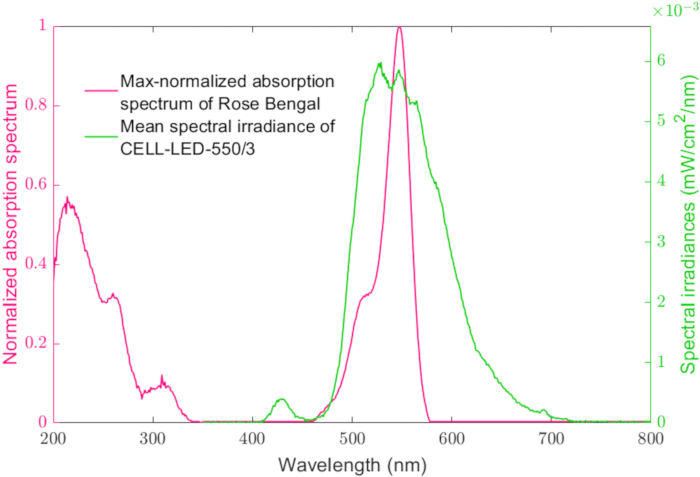
Figure 6: Absorption spectrum of Rose Bengal in water. The max-normalized absorption spectrum of Rose Bengal in water is plotted according to the left axis, and the mean spectral irradiance of CELL-LED-550/3 is scaled according to the right axis. The profile of the mean spectral irradiance is consistent with that of the LED available on the manufacturer's website. Please click here to view a larger version of this figure.
The optical coupling between the two parts of the device is a critical factor. This coupling aims, on the one hand, to collect the maximum of the light emitted by the 3 W LED into a narrow beam and, on the other hand, to inject this beam into the optical fiber bundle. Regarding the first aim, an aspherical collimating lens with a short focal length, specifically designed for PCB (Printed Circuit Board)-mounted LED, allows the concentrate of the 120-degree LED beam into a 10-degree narrow beam with spatially uniform distribution. The resulting beam, moreover, projects images of the square LED chip, which exhibit enhanced clarity and reduced optical aberrations compared to those obtained with the initial beam. As regards the injection of this narrow beam into the optical fiber bundle, four important points need to be addressed. First, the proximal extremities of the 96 0.5 mm diameter PMMA (polymethyl methacrylate) optical fibers (numerical aperture: 0.2) are gathered together into a homemade connector so that they form a square light-receptive surface of sides 5 mm (Figure 7). A square shape, in line with the square projections of the LED chip by the beam, was preferred to the usual round one for the connector so as to limit the light loss. Second, the homemade connector was both designed to require no glue and 3D-printed using a crystal-clear resin in order to limit light absorption and thus to prevent material overheating/carbonization. Third, the light-receptive surface as well as the final surface of the connector were polished using a polishing wheel so that the maximum light passes through them. Fourth and finally, the distance between the lens and the square light-receptive surface was theoretically determined and then adjusted on an optical bench so that the most homogeneous central part of the square LED projection overlaps a little more than the light-receptive surface.
With such a coupling, a power of 1.25 W is obtained for the 10-degree narrow beam, while the total power transmitted by the bundle of 96 optical fibers is 0.12 W (a photodiode sensor suitable for LED light (OPHIR) was used).
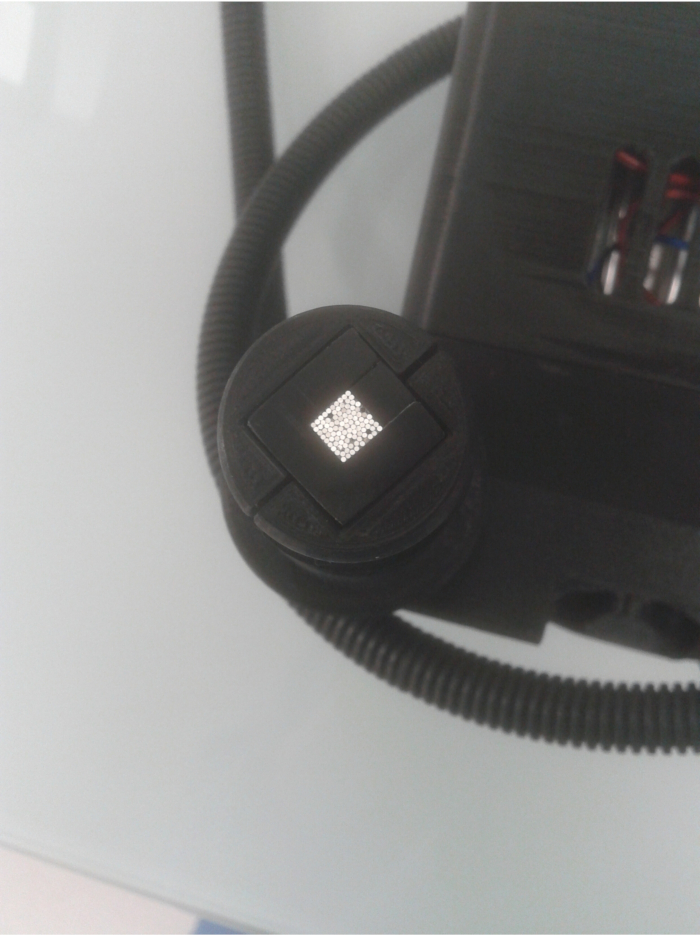
Figure 7: Square light-receptive surface obtained by gathering the 96 optical fibers together into a homemade connector. Please click here to view a larger version of this figure.
CELL-LED-550/3 delivers a mean irradiance of 0.62 mW/cm2 (standard deviation: 0.09 mW/cm2) (Figure 8) at the bottom exterior surface of the wells. This mean value, which takes account for the above-mentioned coupling efficiency, was estimated and proved to be stable over time (variation coefficient lower than 0.6%) according to the methodologies described in details in Lefebvre and al.30. With such a low irradiance (lower than those delivered by the above-discussed other LED-based systems specifically designed for 96-well plate illumination), illumination alone has been proven to have no effect on HepG2 cell viability whereas a very high efficiency has been reached for RB-mediated PDT. For PDT protocols that require higher irradiances to ensure efficiency, multiple LEDs could be used, and therefore multiple light source parts could be implemented, provided that the light power injected into each optical fiber does not exceed the admissible power of some dozens of milliwatts.
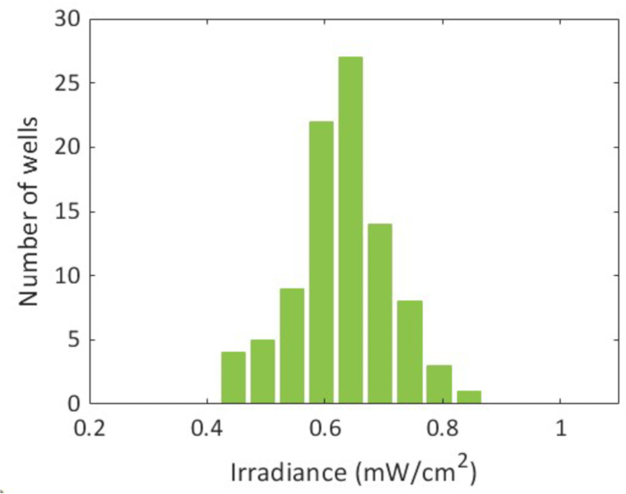
Figure 8: Histogram representing the distribution of the irradiances delivered to the 96 wells of a plate. Please click here to view a larger version of this figure.
Substituting only the LED in the light source part with another suitable one makes it possible to obtain another CELL-LED device. An LED shall be considered suitable if it emits an optical power lower than 5 W (for the reasons mentioned above) in the visible range (according to the specifications of the optical fiber bundle). As there exists a significant number of such LEDs, a wide variety of CELL-LED devices could be developed and, thereby, many PDT protocols could be evaluated in vitro. Given a PDT protocol, the LED providing the best overlap with the absorption spectrum of the considered photosensitizer should obviously be preferred among all the suitable LEDs. In the case of a change of LED, particular attention should be paid to the fan heat sink assembly. In fact, this assembly should be appropriately sized to prevent overheating and subsequent degradation of both the LED and the driver. Moreover, a new optical and thermal characterization will be required for any LED change.
Both the possibility of photo-activating most photosensitizers by simple substitution of a single LED, and the possibility of illuminating the cells inside an incubator provide a real added value to this device compared with the existing ones.
Disclosures
The authors declare no conflicts of interest.
Acknowledgements
The authors would like to thank the Central Hospital of Lille, France, and INSERM for their support of our study.
Materials
| Name | Company | Catalog Number | Comments |
|---|---|---|---|
| 550 nm 3 W LED mounted on a printed circuit board | OSRAM | OSTAR KP CSLPM1.F1 | |
| 75 cm2 Culture cell flask | Sarstedt | 3911002 | |
| Bundle of 100 plastic optical fiber (0.5 mm diameter) | ARCENCIEL LED | fibre05egm | Glow End PMMA 0,5 dia - Lng 200 m http://arcenciel-led.fr/accueil/193-fibre-optique-end-glow-05mm-prix-au-m.html |
| Cell counter | ThermoFisher | AMQAF2000 | Optionnal, you can count under micrcoscope |
| Cell Culture incubator | PHCI (Dutscher) | MCO-170AICUVD-PE | |
| Cell Titer Glo | Promega | G7571 | |
| Clear PMMA collimating lens | Glecc store | 14mm Lens 10° | Aliexpress - DEL collimating lens with 14 mm support |
| Colorfab Ngen Black | Colorfab | SKU 020014 | FDA food contact compliance |
| Colorfab Ngen White | Colorfab | SKU 020013 | FDA food contact compliance |
| Current driver with tri-mode dimming (CDM Driver) | CDM Driver | BD39 | 2200 mA |
| Epoxy resin | Cléopatre | Crystal'Diamond | Cristal Diamond 150 mL |
| Fan heat sink assembly | BOYD | ||
| HepG2 cells | ATCC | HB-8065 | |
| Multimodal Reader (CLARIOstar Plus) | BMG Labtech | 430-2927 | |
| Phosphate Buffer solution | ThermoFisher | 20012-068 | |
| PMMA (polymethyl methacrylate) optical fibers (numerical aperture: 0.2) | Guangzhou Mayki Lighting Limited | ||
| Power jack | RSpro | 907-5680 | |
| RMPI 1640 | ThermoFisher | 21875-091 | |
| Rocker switch | RSpro | 419-744 | |
| Rose Bengale | ThermoFisher / Merck | A17053.14 / 330000-1G | |
| Scratchproof mylar sheet | RSpro | RS: 785-0802 | |
| Sheath | AUPROTECT | Ø 8,5 mm / Ø ext 11 mm | PP Polypropylène UV proof black corrugated sheath not split |
| SVF | Eurobio | CVF SVF00-01 | |
| Tracing paper | Canson | 79368730 | |
| Transparent PMMA plate | RSpro | RS: 284-6269 | |
| Trypan blue | ThermoFisher | 15250061 | |
| Trypsine | ThermoFisher | 25200-072 | |
| Ultimaker 2+ | Ultimaker | ||
| white clear bottom 96-well plate | Dutscher | 655098 |
References
- Sung, H., et al. Global Cancer Statistics 2020: GLOBOCAN Estimates of incidence and mortality worldwide for 36 cancers in 185 countries. CA Cancer J Clin. 71 (3), 209-249 (2021).
- Llovet, J. M., et al. Hepatocellular carcinoma. Nat Rev Dis Primer. 7 (1), 1-28 (2021).
- Erstad, D. J., Tanabe, K. K. Hepatocellular carcinoma: Early-stage management challenges. J Hepatocell Carcinoma. 4, 81-92 (2017).
- Tabori, N. E., Sivananthan, G. Treatment options for early-stage hepatocellular carcinoma. Semin Intervent Radiol. 37 (5), 448-455 (2020).
- Tsuchiya, N., et al. Biomarkers for the early diagnosis of hepatocellular carcinoma. World J Gastroenterol. 21 (37), 10573-10583 (2015).
- Puisieux, M. F., et al. Therapeutic management of advanced hepatocellular carcinoma: An updated review. Cancers. 14 (10), 2357(2022).
- Morton, C. A., et al. European dermatology forum guidelines on topical photodynamic therapy 2019 Part 1: treatment delivery and established indications - actinic keratoses, Bowen's disease and basal cell carcinomas. Eur Acad Dermatol Venereol. 33 (12), 2225-2238 (2019).
- Plaetzer, K., Krammer, B., Berlanda, J., Berr, F., Kiesslich, T. Photophysics and photochemistry of photodynamic therapy: Fundamental aspects. Lasers Med Sci. 24 (2), 259-268 (2009).
- Agostinis, P., et al. Photodynamic therapy of cancer: An update. CA Cancer J Clin. 61 (4), 250-281 (2011).
- Castano, A. P., Demidova, T. N., Hamblin, M. R. Mechanisms in photodynamic therapy: Part two-cellular signaling, cell metabolism and modes of cell death. Photodiagnosis Photodyn Ther. 2 (1), 1-23 (2005).
- Krammer, B. Vascular effects of photodynamic therapy. Anticancer Res. 21 (6B), 4271-4277 (2001).
- Falk-Mahapatra, R., Gollnick, S. O. Photodynamic therapy and immunity: An Update. Photochem Photobiol. 96 (3), 550-559 (2020).
- Mosaddad, S. A., et al. Photodynamic therapy in oral cancer: A narrative review. Photobiomodul Photomed Laser Surg. 41 (6), 248-264 (2023).
- Guidolin, K., et al. Photodynamic therapy for colorectal cancer: A systematic review of clinical research. Surg Innov. 29 (6), 788-803 (2022).
- Osuchowski, M., Bartusik-Aebisher, D., Osuchowski, F., Aebisher, D. Photodynamic therapy for prostate cancer - A narrative review. Photodiagnosis Photodyn Ther. 33, 102158(2021).
- Gustalik, J., Aebisher, D., Bartusik-Aebisher, D. Photodynamic therapy in breast cancer treatment. J Appl Biomed. 20 (3), 98-105 (2022).
- Domka, W., et al. Photodynamic therapy in brain cancer: mechanisms, clinical and preclinical studies and therapeutic challenges. Front Chem. 11, 1250621(2023).
- Crous, A., Abrahamse, H. Photodynamic therapy of lung cancer, where are we. Front Pharmacol. 13, 932098(2022).
- Calzavara-Pinton, P. G., et al. Methylaminolaevulinate-based photodynamic therapy of Bowen's disease and squamous cell carcinoma. Br J Dermato. 159 (1), 137-144 (2008).
- Basset-Seguin, N., et al. Topical methyl aminolaevulinate photodynamic therapy versus cryotherapy for superficial basal cell carcinoma: A 5 year randomized trial. Eur J Dermatol. 18 (5), 547-553 (2008).
- Szeimies, R. M., et al. A clinical study comparing methyl aminolevulinate photodynamic therapy and surgery in small superficial basal cell carcinoma (8-20 mm), with a 12-month follow-up. J Eur Acad Dermatol Venereol. 22 (11), 1302-1311 (2008).
- The IMmunotherapy Pleural 5-ALA PDT. , ClinicalTrials.gov. At https://clinicaltrials.gov/study/NCT04400539 (2025).
- Blue-Light Photodynamic Therapy and Sonidegib for Multiple Basal Cell Carcinomas. , ClinicalTrials.gov. At https://clinicaltrials.gov/study/NCT06623201 (2025).
- Neoadjuvant PDT in the Treatment of Cholangiocarcinoma. , ClinicalTrials.gov. At https://clinicaltrials.gov/study/NCT04824742 (2025).
- Correia, J. H., Rodrigues, J. A., Pimenta, S., Dong, T., Yang, Z. Photodynamic therapy review: principles, photosensitizers, applications, and future directions. Pharmaceutics. 13 (9), 1332(2021).
- Bartusik-Aebisher, D., Ożóg, Ł, Domka, W., Aebisher, D. Rose Bengal and future directions in larynx tumor photodynamic therapy. Photochem Photobiol. 97 (6), 1445-1452 (2021).
- Srivastav, A. K., et al. Photosensitized rose Bengal-induced phototoxicity on human melanoma cell line under natural sunlight exposure. J Photochem Photobiol. B, Biology. 156, 87-99 (2016).
- Uddin, M. M. N., et al. Encapsulated Rose Bengal enhances the photodynamic treatment of triple-negative breast cancer cells. Molecules (Basel, Switzerland). 29 (2), 546(2024).
- Osuchowski, M., et al. Photodynamic therapy-adjunctive therapy in the treatment of prostate cancer. Diagnostics (Basel, Switzerland. 12 (5), 1113(2022).
- Lefebvre, A., et al. Photodynamic therapy using a Rose-Bengal photosensitizer for hepatocellular carcinoma treatment: Proposition for a novel green LED-based device for in vitro investigation. Biomedicines. 12 (9), 2120(2024).
- Bounds, A. D., Bailey, R. D., Adams, C. T., Callaghan, D. C., Girkin, J. M. LightBox: A multi-well plate illumination system for photoactive molecule characterization. J Biophotonics. 14 (5), e202000481(2021).
- Zhang, K., Timilsina, S., Waguespack, M., Kercher, E. M., Spring, B. Q. An open-source LED array illumination system for automated multi-well plate cell culture photodynamic therapy experiments. Sci Rep. 12 (1), 1-10 (2022).
- optoWELL. , opto biolabs. at https://optobiolabs.com/products/optowell/ (2025).
- Repina, N. A., et al. Engineered illumination devices for optogenetic control of cellular signaling dynamics. Cell Rep. 31 (10), 107737(2020).
- Hopkins, S. L., et al. An in vitro cell irradiation protocol for testing photopharmaceuticals and the effect of blue, green, and red light on human cancer cell lines. Photochem Photobiol Sci. 15 (5), 644-653 (2016).
- Hadis, M. A., et al. Development and application of LED arrays for use in phototherapy research. J Biophotonics. 10 (11), 1514-1525 (2017).
Reprints and Permissions
