In vivo confocal microscopy is a promising imaging technique with high resolution. We present the following procedure for clinicians to detect Demodex at the eyelid margin in vivo.
A subscription to JoVE is required to view this content. Sign in or start your free trial.
Method Article
In Vivo Confocal Microscopy: A Standard Operating Procedure for the Detection of Demodex Mites at the Eyelid Margin
In This Article
Summary
Abstract
Demodex mite infestation can cause inflammation of the eyelid margin, and Demodex blepharitis could give rise to a series of ocular conditions in clinical cases. Numerous physicians diagnose ocular infestation of Demodex mites through eyelash epilation and the observation of eyelashes under light microscopy in vitro. However, the presence of residual mites following eyelash removal and the pain associated with the procedure are limitations of standard clinical care.
In vivo confocal microscopy (IVCM) is a non-invasive imaging technique that allows clinicians to observe Demodex mites at the eyelid margin in detail without epilation. This technique enables painless analysis that can be completed in <30 min. Despite growing attention being paid to this examination, it may be inaccessible to many ophthalmologists without extensive experience. This paper presents a standard operating procedure for the visualization of Demodex mites at the eyelid margin with IVCM to promote increased adoption of this method in clinical work.
Introduction
Blepharitis is one of the most commonly encountered ophthalmic diagnoses in clinical practice. Evidence suggests a significant association between the presence of Demodex mites and blepharitis1. The infestation of mites involves both the direct damage caused by Demodex2 and immune responses triggered by its secretions,which may act as a vector for bacteria and potentially contribute to the development of blepharitis3. Demodex blepharitis(DB) causes a spectrum of unsatisfactory events, including damage to the cornea and ocular surface1, which negatively impact a patient's quality of life4,5.
Demodex is a parasitic mite that inhabits hair follicles and sebaceous glands, as well as the areas near them6. Detecting Demodex in or around eyelash follicles can aid in the diagnosis of DB7. The clinical diagnosis of DB involves eyelash epilation and the observation of Demodex under light microscopy. However, it is recognized that many mites residing deep within the follicle may remain in the orifice following eyelash removal8,9,10, potentially leading to an underestimation of the mite count. In vivo confocal microscopy (IVCM), a non-invasive imaging tool in ophthalmology, offers an alternative approach for visualizing Demodex in or around eyelash follicles in vivo11. This technique provides an insight into microstructures of the ocular surface and eyelids with histology-like resolution11. Mites can be visually identified based on their characteristic morphology and motility. However, IVCM may present technical challenges for ophthalmologists lacking extensive experience with this imaging modality12.
To facilitate the adoption of IVCM in routine clinical applications, including the differential diagnosis and follow-up of healthy eyelids as well as DB, we propose a standard operating procedure (SOP) for observing Demodex mites at the eyelid margin. This protocol provides clinicians with a systematic approach for mite detection in vivo.
Access restricted. Please log in or start a trial to view this content.
Protocol
This protocol focuses on the SOP used for observation of Demodex at the eyelid margin with IVCM (Figure 1). This study was approved by the Institutional Review Board (IRB) of the Eye Hospital, Wenzhou Medical University (IRB approval No. H2023-022-K-20), and the requirement for individual consent for this retrospective analysis was waived due to the retrospective nature. The procedures described here reference the descriptions that have been reported previously11,13,14,15,16.
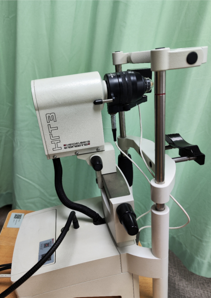
Figure 1: The tomography device. Please click here to view a larger version of this figure.
1. Prepare the device and the program
- Turn on the computer.
- After the desktop appears, switch the rocker switch on the back of the device from O to I. Look for the green glow of the rocker switch indicating that the device is powered on before starting any examinations.
NOTE: Switching on the device before starting the computer may result in connectivity failure. - Start the software and set the program settings before the examination. In the Setup menu, select Options (Supplemental File 1: Supplemental Figure S1); then, check the Show image numbers box to display the image number for each image. Additionally, check the Show information on exit box to prevent the unintentional shutdown of the software.
NOTE: Displaying the image thumbnails as large icons facilitates direct observation of the results. Do not change the settings frequently.
- After the desktop appears, switch the rocker switch on the back of the device from O to I. Look for the green glow of the rocker switch indicating that the device is powered on before starting any examinations.
- Preparations before the examination
- Clean the lens with lens cleaning wipes. Disinfect the headrest and the chinrest with alcohol-soaked cotton balls to avoid infections resulting from pathogenic germs transmitted by dirty device parts.
- Adjust the chinrest. Make sure that the horizontal position of the chinrest is correct: press together the two black levers to pull the chinrest forward until it catches.
- Move the camera backward. Turn the adjustment screw to make sure it moves away from the patient before the examination.
- Apply a drop (approximately 0.02 mL) of Carbomer-based ophthalmic gel as contact gel on the front surface of the microscope lens of the device.
NOTE: Ensure that the contact gel is free of air bubbles and that only a small quantity is used. Too much contact gel applied on the front surface of the microscope lens of the device can flow into the objective and adhere to the mechanical components, leading to damage to the device. - Remove a sterile, disposable polymethylmethacrylate (PMMA) cap from its protective cover and press the sides of the cap firmly on the microscope lens of the device without touching the anterior surface of the cap (Figure 2).
NOTE: To fit the PMMA cap correctly, ensure that the contact gel is in contact with the posterior surface of the cap without any air bubbles. The caps are stored in the dedicated container to prevent damage to the sterile package. Do not use caps with damaged packaging, which may carry the risk of infections during the examination. - Apply a single drop of gel tear substitute on the front surface of the cap as a gel bridge between the cap and the eyelid (Figure 2).
NOTE: To avoid confusion between the gels, we use the same Carbomer-based ophthalmic gel for both applications: the gel tear substitute and the gel used as the agent between the microscope lens and the cap. - Create a New Patient File or select an existing patient file.
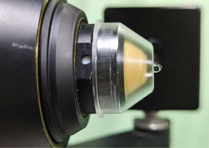
Figure 2: The correct fitting of the PMMA cap and gel application. Please click here to view a larger version of this figure.
2. Prepare the patient
NOTE: Do not perform this examination if the corneal integrity is questionable.
- To obtain the patient's cooperation and minimize potential risks, explain the following to the patient:
- Assure the patient that the examination with the device is safe even though it touches the eyelid. Inform the patient that their eye will be anesthetized by a drop of a topical anesthetic at the eyelid margin.
- When starting the examination, ask the patient to place their chin on the chinrest and lean their forehead against the foreheadrest throughout the examination procedure for the best image quality.
- Inform the patient that the device will be moved close to their eyelid until the PMMA cap touches it. Assure them that they will not feel any pain while the device touches their eyelid, although they will feel the contact of the PMMA cap. Ask them to let the clinician know immediately if they feel any pain during the examination.
- Inform the patient that they must hold their gaze steady while the clinician acquires images of the eyelid margin for the observation of the Demodex. Ask the patient to let the clinician know if they feel any fatigue; they will be allowed to sit back and rest for a while before the examination is continued. They will be informed once the examination is finished.
- Follow the instructions on the topical anesthetic and/or eye gel packaging to avoid drug contraindications. Ask the patient whether they have any allergies to confirm that the patient's allergies are not contraindications of the topical anesthetic and/or eye gel.
NOTE: Allergic reactions to the topical anesthetic and/or eye gel may occur as a result of unidentified allergies. - Apply a drop of Proparacaine hydrochloride, a topical anesthetic, at the margin of the eyelid to be examined.
NOTE: If an allergic reaction occurs, rinse with saline immediately.
3. Perform an examination
- Observe the right eye first. Move the scanning camera to the left from the operator's point of view. OD will be selected automatically in the Settings section by the right-left recognition of the camera.
- Move the CCD camera to the left. Turn the CCD camera objective lens to adjust the image of the CCD camera (the control image) perpendicularly to the optical axis of the scanner laser camera.
- Start a new examination.
- Observe the Examination Data dialog box and in the Examination Data tab, select Heidelberg Retina Tomograph-Cornea from the Device dropdown list (Supplemental File 1: Supplemental Figure S2), and observe the Cornea Module Settings dialog box that appears.
- Select FOV 400 from the Field Lens dropdown list and click OK to confirm (Supplemental File 1: Supplemental Figure S3).
- Wait until the acquisition window opens; the scanning laser camera live image and the control image are displayed. If the control image is not displayed, ensure that the CCD camera cable is correctly connected to the CCD camera, and then restart the acquisition window.
- Set the factors in the acquisition window (Supplemental File 1: Supplemental Figure S4): select 1x from the CCD Zoom Factor dropdown list to set the control image size. Check the Automatic Brightness box and the Auto box to automatically control the brightness of the live and control images. However, if the automatic brightness control is deactivated, use the slider to control the brightness of the control and live images. Check that scan type of Section has been selected so that a single image is acquired and stored each time the footswitch is pressed.
- Acquire a reference image.
- Before starting an acquisition, turn off the automatic brightness control and move the slider to the left to adjust the image brightness. Adjust the focal plane with the adjusting pin so that the initial bright reflection is displayed in the scanning laser camera live image after turning dark, indicating the anterior surface of the PMMA cap.
NOTE: The microscope allows for 10 µm focal adjustments. - Click Reset in the Focus Position [µm] section and wait for the Focus Position [µm] value to turn to 0; the current image is denoted as the reference image. Switch off Auto Reset, and check the Automatic Brightness box; the brightness of the live image will be automatically controlled.
- If dashed lines are displayed instead of values in the Focus Position [µm] section, or if the displayed values do not change despite adjustments to the focal plane, ensure that the microscope lens cable is correctly connected.
NOTE: The Focus Position [µm] for pachymetry displays the focal plane position of the currently displayed image in microns. If the focal plane is moved subsequently, the actual focal plane location is calculated with respect to the position of the reference image.
- Before starting an acquisition, turn off the automatic brightness control and move the slider to the left to adjust the image brightness. Adjust the focal plane with the adjusting pin so that the initial bright reflection is displayed in the scanning laser camera live image after turning dark, indicating the anterior surface of the PMMA cap.
- Elevate or lower the height of the examination table for the patient. Place the patient's chin on the chinrest and the forehead against the forehead rest (Figure 3A,B). Adjust the chin rest elevation via the designated black adjustment screw of the device so that the patient's upper eyelids align with the red marks on the headrest column.
- Tell the patient to look down ahead of the pointer's fixed light source and hold their gaze steady (Figure 3A,B).
NOTE: Eye movement during image collection might result in bad image quality and damage to the ocular surface. - Use a cotton swab to flip the upper eyelid, fully exposing the eyelash root and palpebral margin. Position the reflection of the laser beam on the level of the patient's upper eyelid by turning the adjustment screw of the device. Move the scanning laser camera slowly toward the patient's upper eyelid margin until it gently touches the center of the PMMA cap vertically (Figure 3C). If the patient reports discomfort, pause and check the PMMA cap alignment.
NOTE: Do not apply too much pressure on the patient's eyelid. Contact between the PMMA cap and the patient's eyelid due to an insufficient gel bridge, eye and head movement of the patient, and/or a too strong camera movement of the operator might injure the ocular surface and eyelid. - Scan the root of the eyelash from the temporal side toward the nasal side of the eyelid margin carefully with minute horizontal movements of the palpebral margin, allowing the evaluation of the eyelashes and their follicles. Scan and acquire images by turning the device's microscope lens clockwise or counterclockwise, modify the focus plane gradually to observe the whole follicle and eyelash root, and make a note of the different depths displayed in the scanning laser camera live image. Acquire images by scanning six to ten eyelash hair follicles per eye, with sampling distributed across the temporal, middle, and nasal regions of the eyelid margin.
NOTE: If a small reflex is displayed in the scanning laser camera live image and persists when changing the focal plane position, this may indicate the presence of air bubbles in the contact gel. To resolve this issue, renew the contact gel. - Save the images manually and record all suspected images of Demodex mites by pressing on the foot pedal. Enable pedal audio feedback to verify successful image acquisition. If no eyelid structures are displayed and only highly reflective boundary layers are visible in the scanning laser camera live image, this may indicate that the contact between the PMMA cap and the patient's eyelid margin is interrupted. To resolve this issue, realign the camera until the PMMA cap correctly touches the patient's eyelid margin.
- If the live image appears blurred, distorted, or does not display the hair follicle structure, these issues may indicate that the patient is moving the head or blinking. Remind the patient to focus on the fixation light to minimize movement. If possible, adjust the brightness, focal plane, and scanning position to improve image quality.
- If the scanning laser camera needs to be adjusted or the patient experiences fatigue or any pain, ask the patient to sit back, move the scanning laser camera backward, and readjust the camera. If the patient continues to experience discomfort during the examination and shows no signs of symptom relief after rest, discontinue and reschedule the procedure to ensure patient safety.
- If a patient is examined several times throughout the day, store all the images in the same examination tab in the image viewing window.
- Examine the left eye, move the camera to the right from the operator's point of view, and wait for OS to be automatically selected. Remove the PMMA cap from the device, fit a new PMMA cap on the microscope lens of the device, and repeat the previous steps.

Figure 3: Patient positioning. (A,B) The patient is positioned. (C) The cap is being adjusted to touch the eyelid. Please click here to view a larger version of this figure.
4. After the examination
- Quit the examination; ensure that the images of the eyelash follicles are stored and that the acquired images are displayed in the image viewing window. If not, the image acquisition may have failed, or the data may not have been saved. First, rule out potential equipment malfunctions, such as software connection issues or pedal failure. After troubleshooting, explain the situation to the patient and repeat the examination.
- Ask the patient not to rub their eyes after the examination until the effect of the local anesthesia has diminished.
- Remove the PMMA cap from the device.
- Clean the microscope lens with lens cleaning wipes.
- Select Sort by acquisition time (fast) in the Options dialog and observe the acquired images of eyelash follicles displayed in order from the temporal side to nasal (Supplemental File 1: Supplemental Figure S5) -- the order of scanning of the root of the eyelash along the eyelid margin. Review all images, select the high-quality images for analysis (Figure 4), and delete low-quality images. Have an observer assess the images for mite presence and record the number of lash follicles with Demodex mites in total for each eye.
NOTE: High-quality images show clear mite morphology, and the imaged portion of the mite should be as large as possible, ideally greater than 100 µm. If high-quality images are unavailable, an independent assessment by a second observer is required. If the results of the two observers are inconsistent, a third observer must adjudicate to resolve the discrepancy and establish the final result for inclusion in the report. - Create reports by placing the high-quality image from the temporal side to the nasal side into the lightbox for the report. From the report templates and mite-counting formats (see Supplemental File 2), select an appropriate report template for describing the results based on the findings of the examination.
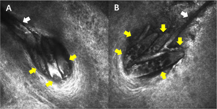
Figure 4: Demodex inside the eyelash follicle. (Images: 400 µm x 400 µm). (A)Three Demodex mites are observed within the follicle (yellow arrow), and a single eyelash is marked (white arrow). (B) Five Demodex mites are observed within the follicle (yellow arrow), and a single eyelash is marked (white arrow). As mites may migrate through different depths, imaging at a single focal plane may capture fragmented portions of individual mites, thereby resulting in incomplete morphological representation. Please click here to view a larger version of this figure.
5. Switch off the device after work every day
- After closing all dialog boxes and windows, close the software.
- Turn off the computer.
- Shut down the device by switching the rocker switch on the back of the device from I to O. For optimal system performance and data security, first shut down the software and then turn off the device.
NOTE: The device should not be kept on continuously for too long, especially for more than a full day. - Regularly maintain the Uninterruptible Power Supply (UPS) connected to the equipment and ensure its proper operation to prevent data loss or device malfunction caused by sudden power outages.
- Perform regular backups such as utilizing Network-Attached Storage (NAS) storage.
Access restricted. Please log in or start a trial to view this content.
Results
Following the SOP described above, we examined patients with suspicion of Demodex infestation in 2024. In addition, we compared the data from 2023 when this SOP had not been applied. As shown in Figure 5, the number of patients who underwent the IVCM for Demodex detection in 2024 is significantly higher than the previous year. This SOP allows the examination of patients of different ages, from 4 years to 92 years old.
Access restricted. Please log in or start a trial to view this content.
Discussion
The ectoparasite Demodex is one of the most common parasites in humans. These mites live in the eyelash follicles, meibomian glands (MGs), and the sebaceous glands and are transparent, elongated in shape, and measure 0.15-0.4 mm in length17. IVCM performed using the device provides 400 µm x 400 µm real-time images with a lateral resolution of 1 µm/pixel and a magnification of 800x. Through IVCM, detailed images of Demodex in the eyelash follicles can be acquired; c...
Access restricted. Please log in or start a trial to view this content.
Disclosures
The authors have no conflicts of interest to disclose.
Acknowledgements
This research was supported by a grant from the National Administration of Traditional Chinese Medicine Science and Technology Department-Zhejiang Provincial Administration of Traditional Chinese Medicine Co-construction Science and Technology Plan (GZY-ZJ-KJ-23086). In vivo confocal microscopy was performed using the Heidelberg Retina Tomograph III with the addition of the Rostock Corneal Module. The authors would like to express gratitude to Heidelberg Engineering GmbH, all the participants and the people working on this standard operating procedure.
Access restricted. Please log in or start a trial to view this content.
Materials
| Name | Company | Catalog Number | Comments |
|---|---|---|---|
| Carbomer-based ophthalmic gel, Vidisic | Bausch and Lomb, Berlin, Germany | 8187195 | |
| Heidelberg Eye Explorer Software | Heidelberg Engineering GmbH, Heidelberg, Germany | version 1.3.3.0 | |
| Heidelberg Retina Tomograph III | Heidelberg Engineering GmbH, Heidelberg, Germany | HRT3-08398 | |
| Proparacaine hydrochloride | Alcon Laboratories, Fort Worth, TX, US | 8387271 | |
| TomoCap | Heidelberg Engineering GmbH, Heidelberg, Germany | 18829 | PMMA cap |
References
- Cheng, A. M., Sheha, H., Tseng, S. C. Recent advances on ocular Demodex infestation. Curr Opin Ophthalmol. 26 (4), 295-300 (2015).
- Czepita, D., Kuźna-Grygiel, W., Czepita, M., Grobelny, A. Demodex folliculorum and Demodex brevis as a cause of chronic marginal blepharitis. Ann Acad Med Stetin. 53 (1), discussion 67 63-67 (2007).
- Clifford, C. W., Fulk, G. W. Association of diabetes, lash loss, and Staphylococcus aureus with infestation of eyelids by Demodex folliculorum (acari: Demodicidae). J Med Entomol. 27 (4), 467-470 (1990).
- O'Dell, L., et al. Psychosocial impact of Demodex blepharitis. Clin Ophthalmol. 16, 2979-2987 (2022).
- Yeu, E., Holdbrook, M. J., Baba, S. N., Gomes, P. J. Psychosocial impact of Demodex blepharitis. Invest Ophthalmol Vis Sci. 62 (8), 1261-1261 (2021).
- Wu, M., Wang, X., Han, J., Shao, T., Wang, Y. Evaluation of the ocular surface characteristics and Demodex infestation in paediatric and adult blepharokeratoconjunctivitis. BMC Ophthalmol. 19 (1), 67(2019).
- Zou, D., et al. Characteristics of bacterial community in eyelashes of patients with Demodex blepharitis. Parasit Vectors. 17 (1), 64(2024).
- Coston, T. O. Demodex folliculorum blepharitis. Trans Am Ophthalmol Soc. 65, 361-392 (1967).
- Mastrota, K. M. Method to identify Demodex in the eyelash follicle without epilation. Optom Vis Sci. 90 (6), e172-e174 (2013).
- Gao, Y. Y., et al. High prevalence of demodex in eyelashes with cylindrical dandruff. Invest Ophthalmol Vis Sci. 46 (9), 3089-3094 (2005).
- Randon, M., et al. In vivo confocal microscopy as a novel and reliable tool for the diagnosis of Demodex eyelid infestation. Br J Ophthalmol. 99 (3), 336-341 (2015).
- Muntz, A., Purslow, C., Wolffsohn, J. S., Craig, J. P. Improved Demodex diagnosis in the clinical setting using a novel in situ technique. Cont Lens Anterior Eye. 43 (4), 345-349 (2020).
- Kojima, T., et al. In vivo evaluation of ocular demodicosis using laser scanning confocal microscopy. Invest Ophthalmol Vis Sci. 52 (1), 565-569 (2011).
- Tas, A. Y. Interobserver and intraobserver agreements of the detection of Demodex infestation by in vivo confocal microscopy. Beyoglu Eye J. 7 (3), 173-180 (2022).
- Wang, Y. -J., Ke, M., Chen, X. -M. Prospective study of the diagnostic accuracy of the in vivo laser scanning confocal microscopy for ocular demodicosis. Am J Ophthalmol. 203, 46-52 (2019).
- hrt3 rostock cornea module user manual v. 1.5 english. , Heidelberg Engineering GmbH. http://www.HeidelbergEngineering.com (2025).
- Lee, S. H., Chun, Y. S., Kim, J. H., Kim, E. S., Kim, J. C. The relationship between Demodex and ocular discomfort. Invest Ophthalmol Vis Sci. 51 (6), 2906-2911 (2010).
- Sattler, E. C., et al. Noninvasive in vivo detection and quantification of Demodex mites by confocal laser scanning microscopy. Br J Dermatol. 167 (5), 1042-1047 (2012).
- Duncan, N., Sood, P., Khandelwal, S. Demodex blepharitis: Its role and treatment in ocular surface disease. Curr Ophthalmol Rep. 10 (4), 107-113 (2022).
- Luo, X., Li, J., Chen, C., Tseng, S., Liang, L. Ocular demodicosis as a potential cause of ocular surface inflammation. Cornea. 36 Suppl 1 (Suppl 1), S9-S14 (2017).
Access restricted. Please log in or start a trial to view this content.
Reprints and Permissions
Explore More Articles
